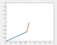
2R Robotic Arm Simulation in MATLAB
2R Robotic Arm Simulation in MATLAB
Aim:
To create a program for 2R Robotic Arm Simulation using MATLAB.
Objective:
To create an animation file of the Robotic arm movement of the plot.
Theory:
Let ‘l1’ be the link 1 attached to the foundation/base and let ‘l2’ be the link 2 connected to ‘l1’. The manipulator is linked to the l2.
Let θ1 and θ2 be the 2 angles made by the 2 arms (l1 and l2) along the x – axis.
Now let us find the co-ordinates of the final position of the manipulator if θ1 and θ2 are the different angels formed by the links.
- We know that the start point of the link 1 will be, (x1,y1) = (0,0)
- Calculating the x1 and y1 distances of link 1.
X1 = l1* cos* θ1
Y1 = l1 *sin* θ1
- Now, calculating the x2 and y2 distances of link 2.
X2 = x1 + l2* cos* θ2
Y2 = y1 + l2 *sin* θ2
- With this let us create a program in MATLAB and create an animation file.
Programming:
1) The standard first 3 lines of code to clear and close all the previous data including the workspace in matlab.

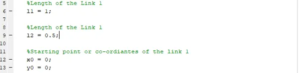
2) Entering the initial fixed quantities like link1 and link2 of the robotic arm. Also x=0 and y=0 to be given as the starting points because from there we are going to calculate the length of the link1,
3) The theta1 is the angle of the link 1 and theta2 is the angle of the link 2 in the robotic arm with respect to the x-axis. The linspace command here gives us 10 equal spaced angles btw 0 to 90 degrees, which we will see in the simulation of the robotic arm.

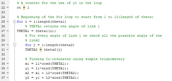
4) The use of the counter ‘ct’ is to keep a track on the number of for loops that have looped and this is helpful for us to store the value of the variable in a counter forming a column vector. Nextly, we begin the first for loop from 1 to length of theta which is 10.
As the first loop begins, the value of theta1 stored in a column vector which consists 10 values go individually with ‘i’ starting from 1,2,3 … 10 and assigns the angle to the variable THETA1. Lastly, the jth for loop is concatenated with the ith for loop to store the value of link 2 for every value of j = 1,2,3 … 10. In short, for every link 1 angle all the link 2 angles are explored with the help of second/inner /jth for loop.
As per our theory mentioned above, we find the values of (x1,y1) and (x2,y2). These value will help us a plot a line diagram of link1 and link2 movements in a simulation of the Robotic Arm.
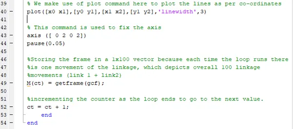
5) Now we Plot the points to form the links btw link 1 and link 2. Here the plot command helps us, to plot the starting and ending points of each line where x0 x1 are the starting and ending points of x-coordinates and y0 y1 are the starting and ending of y-coordinates. Similarly we join the link 1 and link 2 after link is created from 0,0.
The axis command helps us to fix the axis of the plot, which is kept 0 to 2 in both x and y axis.
Pause command pauses the for loop for the number we have specified, in this case we have specified that the pause has to take place for 0.05 second.
M(ct) creates a column matrix of all the frame values, as we know the for loop runs for 10 times x 10 times, which will be 100. So M(ct) will store a 1x100 column vector values of the frame.
getframe: captures the current axis as it appears on the screen as a movie frame.
getframe(gcf): Capture the interior of the figure window, excluding the menu and tool bars.
Finally ct = ct + 1 is the counter incremental which is given, so that the indices changes to the next number as the for loop is running.
End command is important and is used in order to end the for loop, since we have 2 for loops initiated we close them by using the end command.
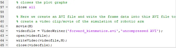
6) The close all command closes all the figure window after the simulation was run.
The movie(M) command is used to convert the get frame values which we assigned to ‘m’ in the above programming lines, to a movie file.
The VideoWriter command in Matlab creates a video file, where we give the inputs of the file name and its extension; say for example .avi or .mp4.
The writeVideo command writes the movie M in to the videofile we just created and assigned the new video file name created to it.
Lastly we close the video file with close(videofile) command. Close(x) is the general syntax of this command which closes the file when we specify the file name inside the parenthesis.
Errors faced and rectified during programming:
1) Error: Incorrect simulation pattern
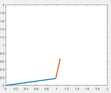
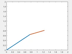
Steps taken to overcome: I forgot to change the variable name theta2 to THETA2, and I faced this issue during simulation. After doing the correction, I was able to get the correct simulation.
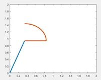
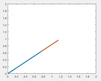
BEFORE AFTER
2) Error: Unrecognized function or variable 'ct'. Error in Forward_kinematic_arm_simulation (line 49) M(ct) = getframe(gcf);
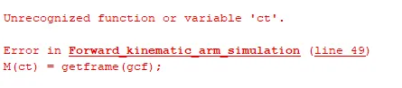
Steps taken to overcome: This is when I realised that I had forgotten to mention ct = 1, before the for loop initiation. After giving ct = 1 outside the for loop I was able to run the program successfully, fulfilling my AIM of the project.
MATLAB CODE:
close all
clear all
clc

%Length of the Link 1
l1 = 1;

%Length of the Link 1
l2 = 0.5;

%Starting point or co-ordiantes of the link 1
x0 = 0;
y0 = 0;

%Angle of link 1 with respect to X-Axis
theta1 = linspace(0,90,10);

%Angle of link 2 with respect to X-Axis
theta2 = linspace(0,90,10);

% A counter for the use of it in the loop
ct = 1

% Beginning of the for loop to start from 1 to 10(length of theta)
for i = 1:length(theta1)
    % THETA1 returns the angle of link 1
THETA1 = theta1(i);

    % For every angle of Link 1 we check all the possible angle of the
    % link2
    for j = 1:length(theta2)
    THETA2 = theta2(j)

    % Finding Co-ordinates using simple trignometery
    x1 = l1*cosd(THETA1);
    y1 = l1*sind(THETA1);
    x2 = x1 + l2*cosd(THETA2);
    y2 = y1 + l2*sind(THETA2);

% We make use of plot command here to plot the lines as per co-ordinates
plot([x0 x1],[y0 y1],[x1 x2],[y1 y2],'linewidth',3)

% This command is used to fix the axis
axis ([ 0 2 0 2])
pause(0.05)

%Storing the frame in a 1x100 vector because each time the loop runs there
%is one movement of the linkage, which depicts overall 100 linkage
%movements (link 1 + link2)
M(ct) = getframe(gcf);

%incrementing the counter as the loop ends to go to the next value.
ct = ct + 1;
    end
end

% closes the plot graphs
close all

% Here we create an AVI file and write the frame data into this AVI file to
% create a video clip/movie of the simulation of robotic arm
movie(M)
videofile = VideoWriter('forward_kienmatics.avi');
open(videofile);
writeVideo(videofile,M);
close(videofile);
Output of the Program:
The program runs for different values of θ1 and θ2. These values create different set of values of x1,y1 and x2,y2. So for each value of θ a line is draw from link 1 and link 2, thus creating a simulation with the help of movie, getframe and write Video commands.
Link to the simulation video: https://youtu.be/q6QISvc-VOM