Modelling the Fuel Cell-Powered Electric Vehicle
FCEVs use a propulsion system like that of electric vehicles, where energy stored as hydrogen is converted to electricity by the fuel cell. Unlike conventional internal combustion engine vehicles, they produce no harmful tailpipe emissions.
 Navin Baskar·5 Jan 2023·3 min read
Modelling the Fuel Cell-Powered Electric Vehicle
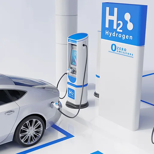
FCEVs use a propulsion system like that of electric vehicles, where energy stored as hydrogen is converted to electricity by the fuel cell. Unlike conventional internal combustion engine vehicles, they produce no harmful tailpipe emissions.
What is the common fuel cell in hydrogen cars?
The most common type of fuel cell for vehicle applications is the polymer electrolyte membrane (PEM) fuel cell. An electrolyte membrane in a PEM fuel cell is sandwiched between a positive electrode (cathode) and a negative electrode (anode). Hydrogen is introduced to the anode, and oxygen (from the air) is introduced to the cathode. The hydrogen molecules break apart into protons and electrons due to an electrochemical reaction in the fuel cell catalyst. Protons then travel through the membrane to the cathode.
These are a few examples of fuel cell-powered vehicles launched in a recent year:
- 2008 - Honda FCX Clarity
- 2015 - Toyota Mirai
- 2016 - Riversimple Rasa
- 2016 - Honda Clarity Fuel Cell
- 2018 - Hyundai Nexo
Understanding the In-Built Fuel Cell Model
You can use the MATLAB Command to open the model
power_fuel_cell
The nominal Fuel Cell Stack voltage is 45Vdc, and the nominal power is 6kW. The converter is loaded by an RL element of 6kW with a time constant of 1 sec. During the first 10 secs, the utilization of the hydrogen is constant to the nominal value (Uf_H2 = 99.56%) using a fuel flow rate regulator. After 10 secs, the flow rate regulator is bypassed, and the rate of fuel is increased to the maximum value of 85 lpm in order to observe the variation in the stack voltage. That will affect stack efficiency, fuel consumption, and air consumption.
Fuel cell voltage, current, DC/DC converter voltage and DC/DC converter current signals are available on Scope2. Fuel flow rate, Hydrogen and oxygen utilization, fuel and air consumption, and efficiency are available on Scope1.
How to change the model of the Fuel Cell?
1. Change the load reference
Here as you can see, a ramp signal is given as a load reference. The ramp signal block act as the flow rate reference. A defined flow rate data can be given as input if you need the model to power an EV. It can depend on the drive cycle of a vehicle. The drive cycle can be for a smaller duration of time (ex:100s) with one peak of acceleration and deceleration.
Use a signal builder block to give the data r add your own excel file data
Keep in mind the data which you are giving is litre per minute or fuel flow rate to the vehicle
2. Change the upper limit value for the flow rate.
The default value given in the block is 85, which is the upper limit value for the ramp signal. The maximum speed value attained during the drive cycle can be given as the upper limit value.
3. Model the fuel stack
Open the fuel cell stack. You can change the PRESET model of the fuel cell from the drop-down menu. Keep the type of cell as PEM because it is the standard type of fuel cell used for EV vehicles. You can give any options from the drop-down menu. If you choose user-defined, you must give a nominal voltage and current specification from a datasheet of a fuel cell-powered EV. Otherwise, keep a genuine range of power ratings and work on the default values. But make sure your load (driving cycle) and the power rating of the fuel cell are compatible. You can try to keep the details as simplified or detailed in the Model detail level.