Understanding Sheet Metal- Bend Radius, K Factor & Bend Allowance
From small light fixtures to automotive body parts, sheet metal parts are used extensively because of their high strength, low weight, and resistance to corrosion. Sheet metals of varying thicknesses are used for different types of machinery as per the respective standards.
 Navin Baskar·4 Jul 2022·2 min read
Understanding Sheet Metal- Bend Radius, K Factor & Bend Allowance
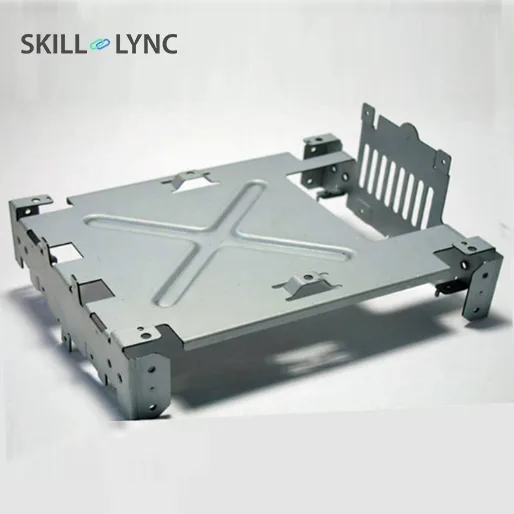
From small light fixtures to automotive body parts, sheet metal parts are used extensively because of their high strength, low weight, and resistance to corrosion. Sheet metals of varying thicknesses are used for different types of machinery as per the respective standards. Sheet metals come from various materials such as steel, aluminium, brass, titanium, and more.
Sheet Metal Measurements:
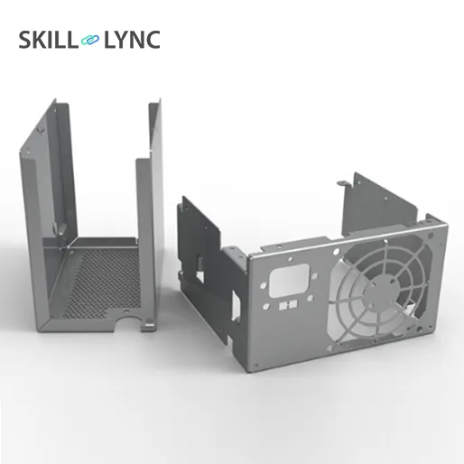
In sheet metal design, the measurement units vary from region to region. In India, we follow the SI unit system for measurements. In the US, the sheet metal parts will be measured with the inch system. In some parts of the world, the gauge unit measurement system is being followed. In this system, the gauge value depends on the materials used for sheet metal design. When the gauge value increases the thickness of the sheet metal decreases.
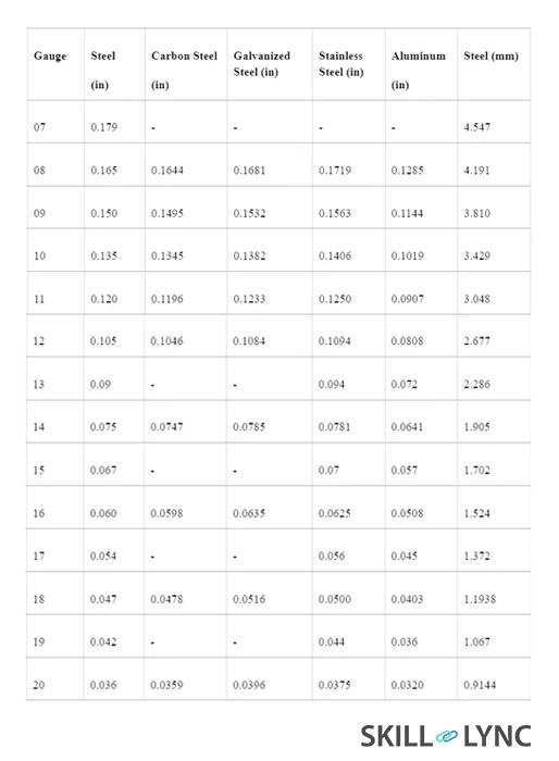
Table 1 shows how the thickness of sheet metal varies based on the material for the same gauge value.
Sheet Metal Terminology
Below are a few terms you should be familiar with while learning about sheet metal:
- Bend Radius:
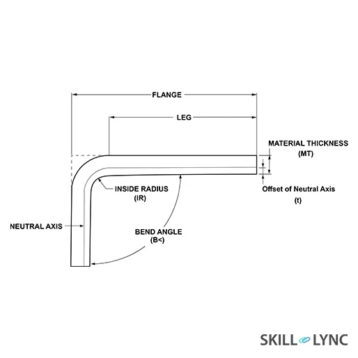
During the manufacturing process, the sheet metal is bent to the required angle by the press brakes. These brakes are not capable of creating 90-degree bends but only curved ones in sheet metal. The radius of the inside curve is called the bend radius. Every manufacturer has its own standards for the sheet metal bend radius. Adhering to the standards while designing sheet metal bends keep the cost of manufacturing within the budget. Using the bend radius other than the standard value demands a custom tool needs to create the bend, which increases the cost of manufacturing.
- K Factor:
While bending a material during sheet metal design, the inner portion undergoes compression and the outer portion gets stretched. This indicates that the inner length of the bent material decreases and the outer length of the material increases. In between them, there is a line called the ‘neutral line’ where there is no change in length and this is where the transition of compression to tension occurs.
The ratio of the neutral line distance to the material thickness is called the “K-Factor”. The value of the K-Factor depends on the thickness of the material, its properties, and the bend radius.
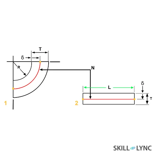
As mentioned above, the material length increases at the outer edge during stretching and decreases during compression. The change in length of the material can be explained by two parameters called bend allowance and bend deduction.
- Bend Allowance:
The bend allowance is defined as the material added to the leg length of the sheet metal to produce a flat pattern.
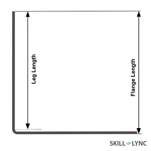
The flange length is the length of the two opposing horizontal or vertical edges. The leg length is the difference between the bend radius from the flange length.
In the flange, the length is 50 mm in both the horizontal and vertical direction and the bend radius is 1 mm. The leg length is 49 mm. The total inside length of the sheet metal is 99.57 mm. If we make the above part into a flat pattern, its total length increases to 103 mm.