Yacht Design in Solidworks using surface modelling
Objective: - Design and Render the individual components of a yacht and assemble them together to foam a good aesthetical Yacht.
Introduction: - A yacht is a motor-powered small ship which sail in sea for pleasure crushing and racing. It is vessel like shape in which it has a cabin with amenities that accommodate overnight use.
Yacht Design is all about creating a dynamic, artful watercraft with nothing more than your imagination, technical skills, and a computer. The design, shape and materials defined by the designer and used in the construction of a boat can make it more energy-efficient, cost-effective and aesthetically pleasing.
Design considerations for a cruising yacht include seaworthiness, performance, sea kindliness, and cost of construction, as follows:
- Seaworthiness addresses the integrity of the vessel and its ability to stay afloat and shelter its crew in the conditions encountered.
- Performance hinges on several factors, including the waterline length (longer means faster), drag in the water (narrower hull with smooth appendages), hull shape, and sail shape and area.
- Sea kindliness is an indicator of steering ease, directional stability and quelling of motion induced by wind and waves.
Here we use SOLIDWORKS tools for 3D design of individual components as well as the assembly of the Yacht.
Design Methodology:
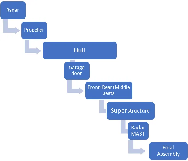
Tools which are used most.
- 3D sketch: It is one of the solid works design tools which helps to design any line or curve in space. In 3D sketching, a graphical space handle helps maintain your orientation while you sketch on several planes. The space handle appears when the first point of a sketch entity is defined on a selected plane. Using the space handle, you can select the axis along which you want to sketch. It helps to join different projected curves in different planes.
- Projected Curve: - It is one of the most used tools in drafting the design. It helps to get a single curve from two different curves drawn on different planes or the same plane. Create a Curve as the intersection of two projected sketches. Note that the projections from one sketch must intersect the other in one continuous curve for this operation to succeed.
- Surface loft: - It is one of the surface tools in solid works to draft the surface. It generates the surface from different 3D curves on different planes. Loft Surfaces are surfaces generated by multiple 3D Curves or existing edges creating a smooth tangency between the selected curves. It is done using a minimum of two profiles and a minimum of one guiding curve. Match Points are created between each selection denoting the orientation and path of the loft surface.
- Surface extrude: - It is one of the surface tools to foam the surface bodies which are thin in nature. we can extrude the boundary edges of a face of a solid body or edges of a surface body in a customized direction.
- Surface fill: - It is one of the surfaces tools used to foam the surface bodies from edges. The Filled Surface feature constructs a surface patch with any number of sides, within a boundary defined by existing model edges, sketches, or curves, including composite curves. we use this feature to construct a surface to fill a gap in a model.
- Surface trim: It is used to trim the non-required/extra surface from the surface.
- Surface knit: - It is one of the most widely used tools in drafting the surface. It knit the different surfaces to make the union of the surface to a single surface. Without knitting, we cannot make our surface bodies solid.
- Mirror- It is used to mirror the object or features wrt to plane or face.
- Extrude, extrude cut - These tools are used in solid bodies to extrude or cut depending upon requirements.
- Swept - iT is used to create one curve and a guiding curve to make a swept body.
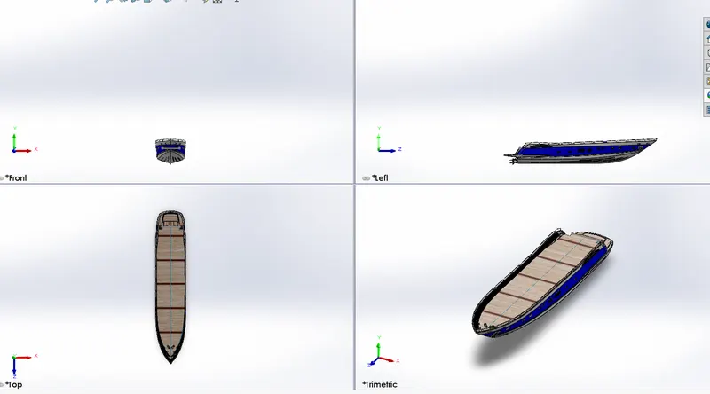
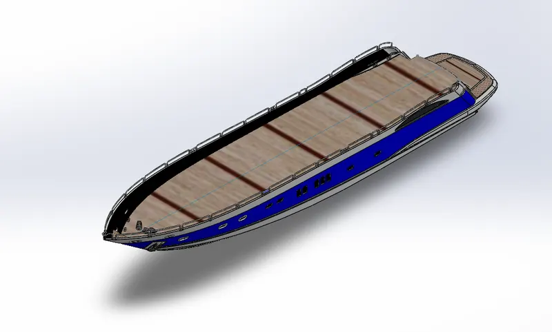
Hull: - A hull is the main body of the yacht. It was submerged in the water. It is a sealed body that is open at the top and it may partially cover with a deck. Where the hull meets the water i.e., called waterlines. At the top of the hull or on its deck surface remaining amenities like superstructures and different seat arrangements lies. This hull was designed with the help of the imported blueprint top, front and side views as shown in the below picture.
- 3D design of Hull in SOLIDWORKS is started from outline the outer surface of the body using the different views image.
- Initially, we use surface modelling to create outer lines then convert it to solid to give the additional features.
- For obtaining the curves at various positions project curve option is used and they are lofted together to form the required surface.
- During the surface extrusion process, unwanted surfaces are being produced which are trimmed using the Trim tool.
- The railing is one of the important features which is designed using projected curves surface swept.
- After creating all the necessary surfaces from all the sides, the surface is being knit using the surface knit option to form a single body and converted it into a solid body.
- The conversion of the solid body only happens when there is no gaps found between the surfaces that are being extruded and trimmed.
- Extra appearance is given by creating different windows and rings and waterlines on the bottom and front surface of the hull.
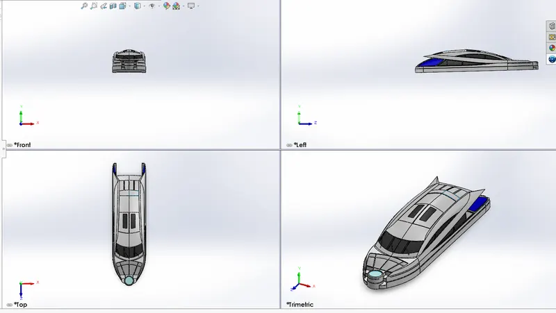
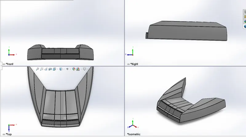
Superstructure: - It is the body that lies on the top surface of the hull i.e. deck. This superstructure was also designed with the help of the imported blueprint top, front and side views as shown in the below picture. It has been done in the following steps.
- Initially, the wall of the superstructure is created by drawing a line on the bottom plane along with the curvature using the spline option and making it constrained using proper dimensions and being surface extruded in the feature manager tab.
- The base wall is trimmed according to the estimated design and another surface is extruded with reference to the base wall edge using ruled surface
- For obtaining the curves at various positions project curve option is used and they are lofted together to form the required surface.
- During the surface extrusion process, unwanted surfaces are being produced which are trimmed using the Trim tool.
- After creating all the necessary surfaces from all the sides, the surface is being knit using the surface knit option to form a single body and converted it to a solid body.
- The conversion of the solid body only happens when there are no gaps found between the surfaces that are being extruded and trimmed.
- The seats attached to the superstructure are extruded out from the line drawn on the midplane and extruded up to the surface and the appearance is created with the help of the dome tool as shown below.
- Extra appearance is obtained on top and rear side of the superstructure is obtained using extrude cut option. For this, the required shapes are drawn on the required plane and are cut using the offset from the surface option present in the selection toolbar present in the extrude option by providing the depth of cut.
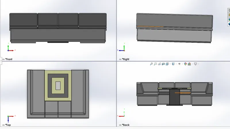
Seats: Three seats are places in the design one on the front of the superstructure, another one is just after the superstructure and last on the outer boundary of the deck. This seat lies on the deck surface of the hull. Following steps are taken to design seats.
- Insert the hull part on the blueprint setup sketch.
- Hide all solid bodies only select the surface i.e., deck.
- Design the front, rear and middle seats according to the different view set up pictures.
- 3D sketch, projected curves, different surface tools (surface extrude, surface loft, surface trim and surface knit) are used to draft the required shape.
- Appearance and extra features are added after converting them to solid bodies.
- Extrude, extrude cut and the dome is used features to give proper design.
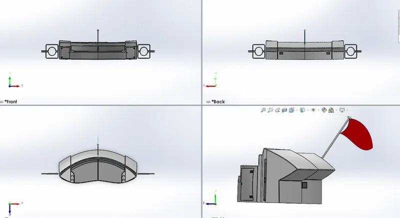
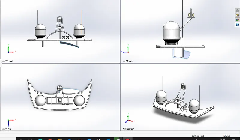
Radar and Radar mast: - Radar and radar mast is attached on top of the superstructure. The radar mast is the base body on which the radar is attached. Both parts are designed using the extrude tools, swept tools and mirroring of the object from the selected face/plane.
Here Radar is a rotating stick that sweeps the incoming microwave signals and radar mast contains the system to produce the outgoing signals using the antenna.
The design of this component involves base creations initially in 20 sketchers and that is being extruded in the features tab.
The lobes on two sides as shown in the picture is drawn on a plane which is created with reference to midplane offset at a required distance and using revolve tool solid cylindrical object is formed on the base. Revolve create a closed sketch with the central axis which helps to form the cylindrical object with reference to the central axis.
The antennas are the circular structures where the circle is being sketched or drafted on the base surface initially and extruded in the features tab.
Horns are created on a newly created reference geometrical plane and using revolve tool circular horn is formed and the front hollow shape has been developed using shell option
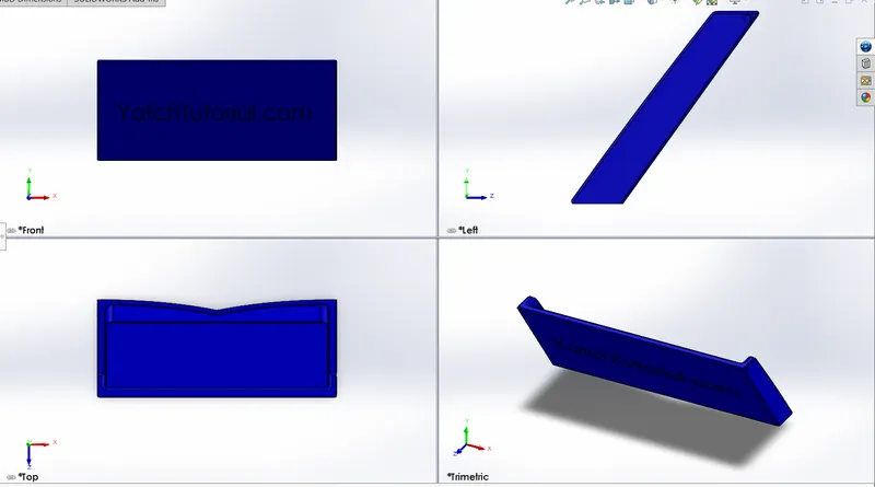
Garage Door- This is a door of the Garage that will connect with the hull base and deck. This garage in Yacht is made up for parking cars and personal vehicles. Following steps are taken for designing of door.
- The garage base part is extracted from the hull to match the same geometry.
- The extrude cut feature is used to cut the extra part of the extracted part.
- Fillet option used to sharp edges of the door.
- Extrude cut option used on the wall of door to create hinge.
- The mirror option is used to make the actual geometry of door.
- Writing on the door will make for aesthetically good.
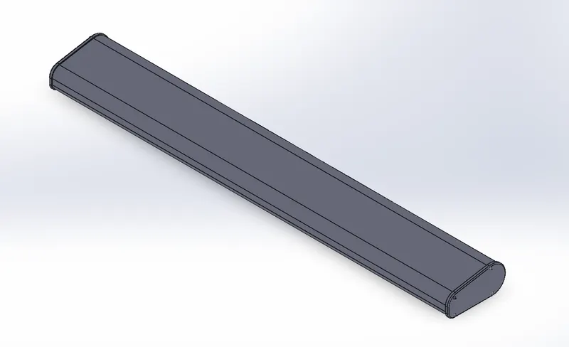
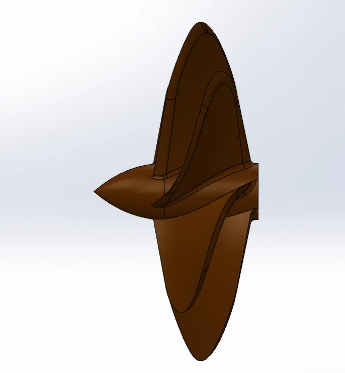
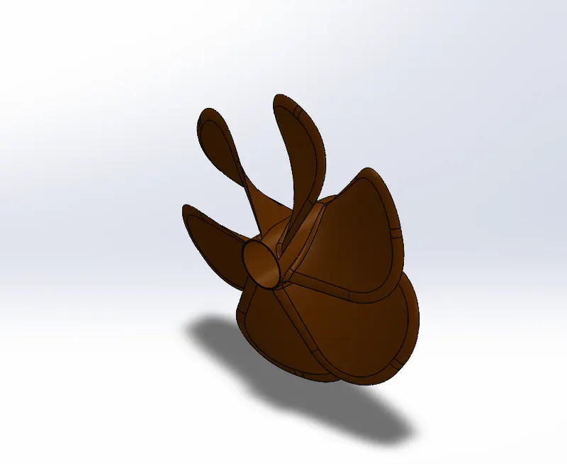
Propeller: -
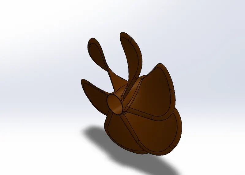
A propeller is a device with a rotating hub and radiating blades that are set at a pitch to form a helical spiral, that. when rotated. performs an action that is similar to Archimedes' screw. It transforms rotational power into linear thrust by acting upon a working fluid, such as water or air.
- For designing the propeller, the main hub is created by a simple sketch line and spline drawn on the front plane and extruded using the revolve option around the centre line.
- The wings are twisted parts created by sketching the two different rectangles on two different surfaces and formed into solid using the loft option.
- The shape of the wings is obtained fillet applied at the two edges on the top side.
- For inserting the shaft, the hole is created by sketching the circle on the hub back end and material is removed using extrude cut option. Colour is applied to the propeller for appearance as shown in the figure
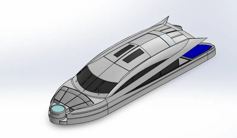
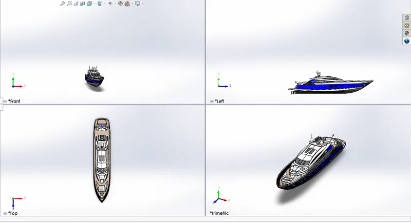
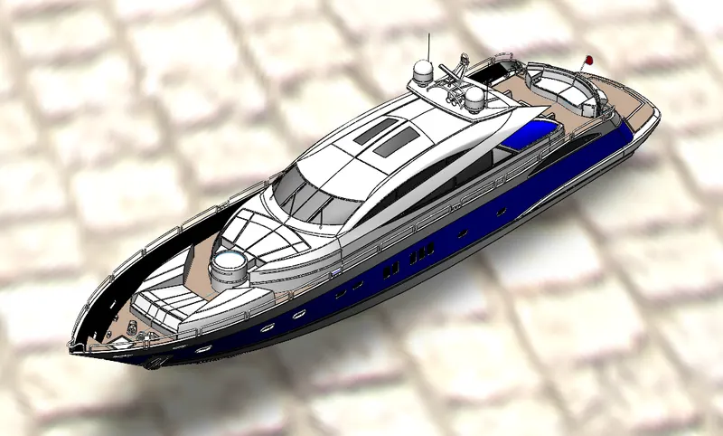
Final Assembly: - All individual components are added to the base part hull to make the final assembly of the Yacht. Some of the parts that were created on the surface are automatically mated. Some components such as the propeller and garage door are assembled using mating.
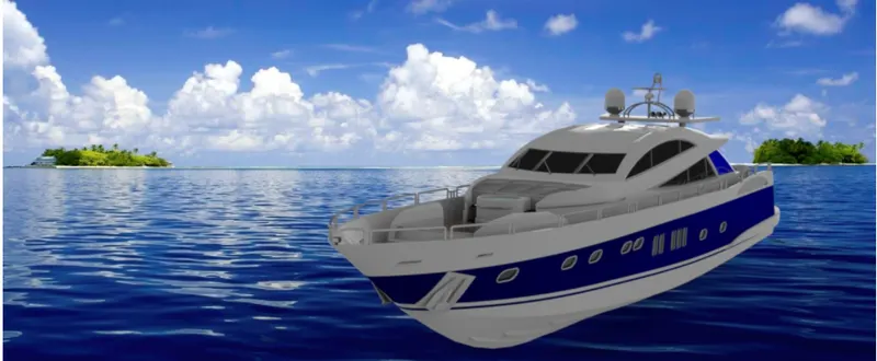
Conclusion
The yacht design is ready.