Write a program in matlab and simulating air standard cycle
Write a program in matlab and simulating air standard cycle.
- Introduction:-
The compression ignition engine are operates on otto cycle and diesel cycle respectively. In this engines the products of combustion are expelled to its surroundings and this makes these engines operates on open cycles. For each cycle fresh charge is introduced. To study the operations and performances of these engines they are represented with theoretical engines operating on thermodynamic cycles and this theoretical engines are referred to as air standard cycles. They are called air standard cycles because their working fluid is majorly taken is air. In this cycles heat is added from an external source as opposed to burning fuel and heat sink is provided as opposed to exhaust thus returning the air back to its original state.
- Objectives:-
- To study on working of otto cycle.
- To calculate thermal efficiency of the cycle using state variables.
- To plot the graph of pv diagram using state variables.
- Theory:-
The four-stroke Otto cycle is made up of the following four internally reversible processes.
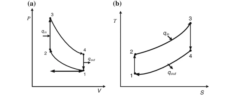
- Isentropic compression process of air takes place from state 1 to state 2
- Constant volume heat addition process takes place from state 2 to state3
- Isentropic expansion process occurs from state 3 to state 4
- Constant volume heat rejection process occurs from state 4 to state 1
It is describes the functioning of a typical spark ignition position engine. In this cycle air-fuel mixture is introduced during the induction stroke and compressed to a much lower compression ratio (around 8:1) and is then ignited by a spark. The combustion results in a sudden jump in pressure while the volume remains essentially constant.
some formulaes using in this cycle:-
- Total Cylinder Volume (V)
V = Vc + Vs Where, Vc= Clearance volume, Vs= Swept volume
2. The compression ratio (cr)
Cr = V / Vc Where, V= Toatal cylinder volume, Vc= Clearance volume
3. Thermal efficiency (n_th)
n_th = 1-(1/(cr^gamma-1)) Where, Cr= Compression ratio, gamma= 1.4
- Governing equations used in program:-
Swept volume (Vs) =`(pi/4)*bore^2*stroke`
Clearance volume (Vc) = `Vs/(Cr-1)`
`V/Vc=1+0.5(Cr-1)[R+1-costheta-(R^2-sin^2theta)^0.5]` .......Using this formula find total volume
where, R = Ratio of connecting rod length to crank pin radius
R = conn_rod/a
a = stroke/2
- Process of program:-
- Starting from clear all data using clear all, close all, and clc commands.
- Give the input put the state variables like preassure at point 1, temperature at point 1 and 3 and for calculation of swept volume and clearance volume require some values like bore, stroke, conn_rod, compression ratio putting their values.
- Calculate swept volume and clearance volume using formula.
- In state point 1 calculations volume at point 1 is addition of swept volume and clearance volume and the volume at point 2 is same as clearance volume.
- After getting volume at point 1 and 2 we calculate pressure at point 2. then using ideal gas law calculate temperature at point 2.
- As we also known process 2-3 is constant volume heat addition process so volume at point 3 and volume at point 2 is same and again using ideal gas law calculate pressure at point 3 which should be higher then other pressure points.
- Considering isentropic expansion process for calculate pressure at point 4 where the volume at point 4 and 1 are equal due to constant volume heat rejection process.
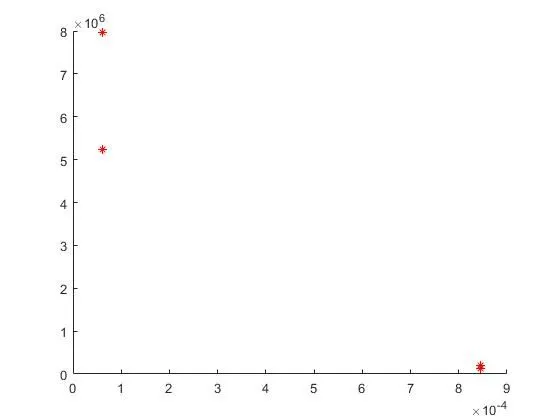
- After calculations of all of point give plot commands of all volume and pressure points and then graph will shown in linear line between each of pressure and volume so hence it is not correct.
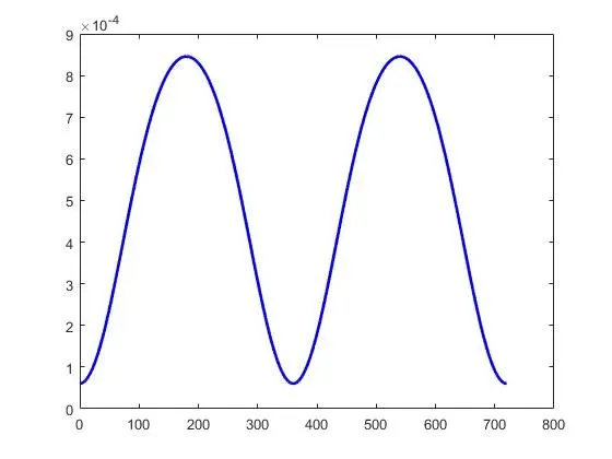
- For giving proper graph we need to calculate actual volume by the piston.
- To calculate actual volume by rthe piston we call the function as name engine_kinematics which have one output variable and six geometric parameters which are defined. as we know folder name and fuction name are must be require same.
- After calculation of actual volume then calculate compression volume and expansion volume for plotting pv diagram.
- For the calculation of compression volume changing the crank angle from 180 to 0 and same as expansion volume from 0 to 180.
- After calculation all equation we can give plot command.
- Labeling x and y axis and give title name for graph.
- Program 1:- Without using function command
%challenge otto cycle
clear all
close all
clc

%inputs
gamma = 1.4;

%state variables
p1 = 130025;
t1 = 540;
t3 = 2360;

%geometrical parameters
bore = 0.1;
stroke = 0.1;
conn_rod = 0.15;
Cr = 14;

%to calculate swept volume and clearance volume
Vs = (pi/4)*bore^2*stroke;
Vc = Vs/(Cr-1);

%state variables at state point 1
%isentropic compression process
v1 = Vs+Vc;
v2 = Vc;
p1 = 130025;

%state variables at state point 2
%constant volume process heat addition
%p1v1^gamma = p2v2^gamma
p2 = p1*(Cr)^gamma;

%using ideal gas law
%p1v1/t1 = p2v2/t2
t2 = (p2*v2*t1)/(p1*v1);

%state variables at state point 3
%isentropic expansion process
%constant volume process at point 2 and 3
v3 = v2
%using ideal gas law
%p2v2/t2 = p3v3/t3
p3 = p2*t3/t2;

%state variables at state point 4
%constant volume process heat rejection
%constant volume process at point 4 and 1
v4 = v1
%p3v3^gamma = p4v4^gamma
p4 = p3*(v3/v4)^gamma;

%thermal efficiency
n_th = 1-(1/(Cr^gamma-1))

%graph 1
figure(1)
hold on
plot(v1,p1,'*','color','r')
plot(v2,p2,'*','color','r')
plot(v3,p3,'*','color','r')
plot(v4,p4,'*','color','r')
- Graph 1:-
- Program 2:- Without function command using
clear all
close all
clc

%geometrical parameters
bore = 0.1;
stroke = 0.1;
conn_rod = 0.15;
Cr = 14;

%inputs
theta = linspace(0,720,720);
gamma = 1.4;

a = stroke/2;
R = conn_rod/a;

Vs = (pi/4)*bore^2*stroke;
Vc = Vs/(Cr-1);

term1 = 0.5*(Cr-1);
term2 = R+1 - cosd(theta);
term3 = (R^2 - sind(theta).^2).^0.5;

V = (1+term1*(term2-term3)).*Vc
plot(theta,V,'linewidth',2,'color','b')- Graph 2:-
- Program 3:- Using function command
%challenge otto cycle
clear all
close all
clc

%inputs
gamma = 1.4;

%state variables
p1 = 130025;
t1 = 540;
t3 = 2360;

%geometrical parameters
bore = 0.1;
stroke = 0.1;
conn_rod = 0.15;
Cr = 14;

%to calculate swept volume and clearance volume
Vs = (pi/4)*bore^2*stroke;
Vc = Vs/(Cr-1);

%state variables at state point 1
%isentropic compression process
v1 = Vs+Vc;
v2 = Vc;
p1 = 130025;

%state variables at state point 2
%constant volume process heat addition
%p1v1^gamma = p2v2^gamma
p2 = p1*(Cr)^gamma;

constant = p1*v1^gamma;
V_compression = engine_kinematics(bore,stroke,conn_rod,Cr,180,0);
P_compression = constant./V_compression.^gamma;

%using ideal gas law
%p1v1/t1 = p2v2/t2
t2 = (p2*v2*t1)/(p1*v1);

%state variables at state point 3
%isentropic expansion process
%constant volume process at point 2 and 3
v3 = v2
%using ideal gas law
%p2v2/t2 = p3v3/t3
p3 = p2*t3/t2;

constant = p3*v3^gamma;
V_expansion = engine_kinematics(bore,stroke,conn_rod,Cr,0,180);
P_expansion = constant./V_expansion.^gamma;

%state variables at state point 4
%constant volume process heat rejection
%constant volume process at point 4 and 1
v4 = v1
%p3v3^gamma = p4v4^gamma
p4 = p3*(v3/v4)^gamma;

%thermal efficiency
n_th = 1-(1/(Cr^gamma-1));

%graph 1
figure(1)
hold on
title('PV Diagram "Otto Cycle"','color','k')
plot(v1,p1,'*','color','r')
plot(V_compression,P_compression,'linewidth',1,'color','b')
plot(v2,p2,'*','color','r')
plot(v3,p3,'*','color','r')
plot(V_expansion,P_expansion,'linewidth',1,'color','b')
plot(v4,p4,'*','color','r')
line([v2 v3],[p2 p3],'linewidth',1,'color','b')
line([v1 v4],[p1 p4],'linewidth',1,'color','b')
xlabel('Volume','color','k')
ylabel('Pressure','color','k')

%graph 2
figure(2)
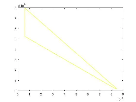
plot([v1 v2 v3 v4],[p1 p2 p3 p4],'linewidth',1,'color','y')
- Graph 3:-
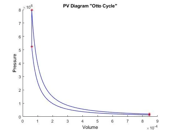
- Graph 4:- Wrong graph because it created linear lines.
- Program 4:- The function engine_kinematics given as.
function  [V] = engine_kinematics(bore,stroke,conn_rod,Cr,start_crank,end_crank)

%inputs
theta = linspace(start_crank,end_crank,100);
gamma = 1.4;

a = stroke/2;
R = conn_rod/a;

Vs = (pi/4)*bore^2*stroke;
Vc = Vs/(Cr-1);

term1 = 0.5*(Cr-1);
term2 = R+1 - cosd(theta);
term3 = (R^2 - sind(theta).^2).^0.5;

V = (1+term1*(term2-term3)).*Vc

end
- Result:-
As we calculate all equations and get thermal efficiency of engine is nearly around 65.20%, the efficiency is increased by increasing compression ratio. The maximum pressure in the engine is around 80MPA, minimum pressureof engine is around 52MPA.
End
Thankyou,
DHARMESH BONDE