Write a code to solve that can solve an otto cycle and makes plots for it.
Aim : Write a code to solve that can solve an otto cycle and makes plots for it.
1. create PV diagram 2. Output the thermal efficiency of the engine.
Theory :
Otto cycle The otto cycle is named after Nikolaus Otto (1832-1891, german) who is credited as the first creator of a petroleum fuel based internal combustion engine operating under a four stroke cycle. Ottos engine work during the eve of the industrial revolutiom was a critical development leading to the dawn of the automotive industry in the late 19th century.
On this cycle petrol, gas and many types of oil engines work. It is the standard of comparison for ineternal combustion engines.
The below diagrams shows the theoretical p-v diagram and T-s diagrams of this cycle respectively.
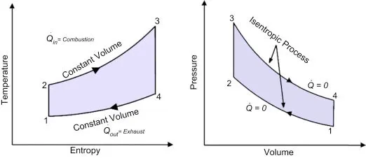
- The point 1 represents that cylinder is full of air with volume V1 pressure p1 and absolute temperature T1.
- Line 1-2 represents the adiabatic compression of air due to which p1, V1 and T1 change to p2, V2 and T2 respectively.
- Line 2-3 shows the supply of heat to the air at constant volume so that p2 and T2 change to p3 and T3 ( V3=V2).
- Line 3-4 represents the adiabatic expansion the air. During expansion p3, V3 and T3 change to final value of p4. V4 or V1 and T4 respectively.
- Line 4-1 shows the rejection of heat by air at constant volume till original state(point 1) reaches.
Formulas used:
1. change in volume inside the cylinder
`V_s/V_c = 1 + 1/2 (r_c-1)[R+1-costheta-(R^2-sin^2theta)^0.5]`
Where,
V_s = swept volume
V_c = clearance volume
cr = compression ratio
R = radius of pistion
2. Thermal efiiciency =
nth = 1-1/(cr^gamma-1)
Where
nth = Thermal efficiency
cr = compression ratio
Objectives :
1. plot p-v diagram
2. Thermal efficeiency of the engine.
Procedure / Explanation of the code :
Step -1 we need to assign the values for cyclinder parameters
bore = 0.1
stroke = 0.1
con_rod = 0.15
cr = 12
Step-2 provide the values at state 2,
gamma = 1.4
t3 = 2300
p1 = 101325
t1 = 500
Step -3 write the eaquations for swept volume and clearance volume
Now we got V1 & V2 values
Step 4 V1,V2, p1, t1, t3, gamma values are known and to obtain p2 value
Write adiabatic process 1-2 : p1V1^gamma = p2V2^gamma
p2 = p1*(v1/v2)^gamma
p2 = p1*cr^gamma
Step 4 Now V1,V2,V3, p1, p2, t1, t3, gamma values are known (Since V2=V3)
Code for Otto cycle p-v Diagram :
Programming language - Matlab
hold on
plot(v1,p1,'*','color','r')
plot(V_compression, P_compression)
plot(V_expansion, P_expansion)
plot(v2,p2,'*','color','r')
plot(v3,p3,'*','color','r')
plot(v4,p4,'*','color','r')plot([v1 v2 v3 v4], [p1 p2 p3 p4], 'color','b')Code for the function : Engine kinematics
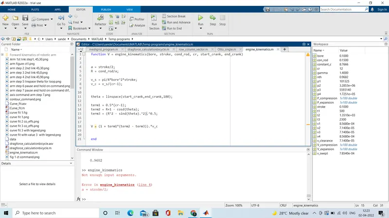
V = (1 + term1*(term2 - term3)).*v_cnth = 1-1/(cr^gamma-1); 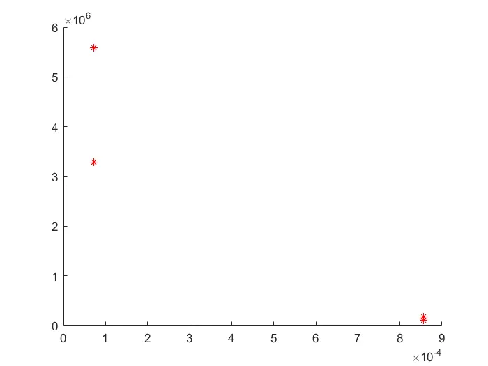
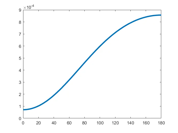
2. Graph for 180values by using linspace command
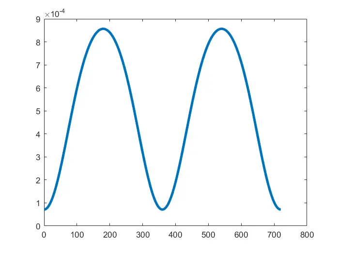
3. Graph for 720 values by using linspace command
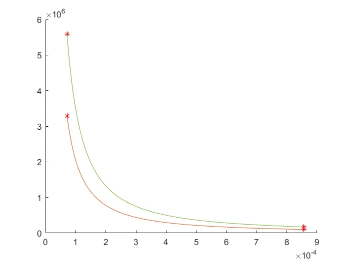
4. garaph of figure 1 for (V_compression, p_compression)(v_expansion, p_expansion)
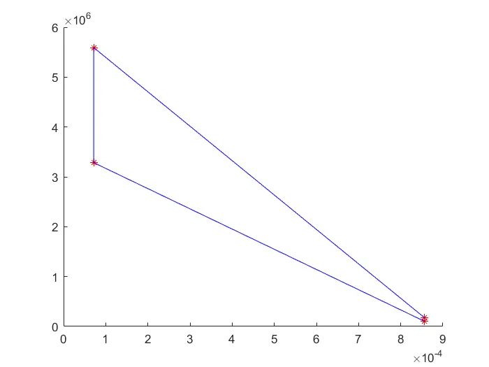
6 . Plotted the graph combining all variables p1,p2,p3,p4 and V1,V2,V3,V4
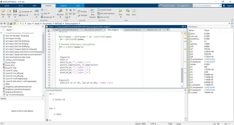
7 . Thermal efficiency of the otto cycle
Errors occured :
1. error occured due to parentheses forgot in an equation and it corrected after error messsage appeared in command window.
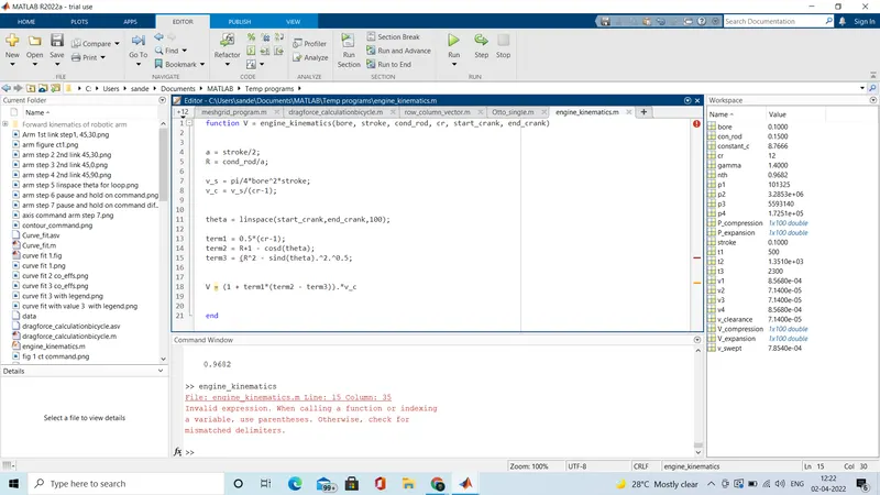
2. Error occured due to some input arguments missed in function of engine kinematics and it is corrected by giving proper input arguments.
References :
1. PV & TS Diagram : https://www.sciencedirect.com/topics/chemical-engineering/otto-cycle
2. Work done equation : https://sist.sathyabama.ac.in/sist_coursematerial/uploads/SMEA1404.pdf