Wiring harness routing & packaging Rules Week 3 Challenge
AIM-:
- Download the "P Clamp" then define Electrical support using Electrical Part design Workbench. Define all the necessary properties.
- Download following Back shell cad data & define it as Electrical back shell using Electrical Part design Workbench. Define all the necessary properties.
- Create Corrugated tubes & Add them in Catalogue under “Slit COT” family.
1. P CLAMP
The P-Clamp's design incorporates a quick-lock feature, which enables users to quickly open and close the clamp as needed without unmounting it. Made of lightweight, aerospace grade PEEK (Polyetheretherketone) polymer, TE P-Clamps come in 10 sizes that cover the same range as 21 standard AS21919 P-Clamps.
P clamps are commonly used in various industries to secure and organize cables, hoses, and other components.
DEFINE ELECTRICAL SUPPORT USING ELECTRICAL PART DESIGN WORKBENCH
Before Wire Harness routing, it is important to define it Electrical part Design Workbench. Important parameter required to define it Electrical Part Design-:
a) Entry Point & Exit Point
b) Plane
c) Define Support part
a) Entry Point & Exit Point
- Go to the "Part Design" workbench.
- Go to the "Reference" then choose "Point" option.
- Choose "Circle/Sphere/Ellipse center" on "Point Type".
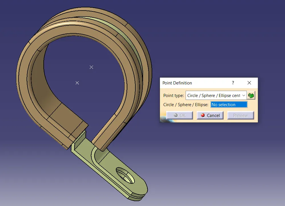
- Select circle and point is created automatically.
- Same follow on another side, thus Entry and Exit point is created.
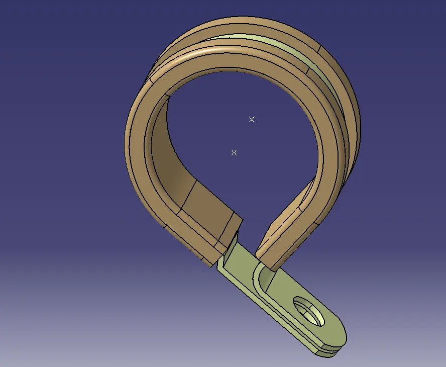
b) PLANE
- Go to the "Part Design" workbench.
- Go to the "Reference" then choose "Plane" option.
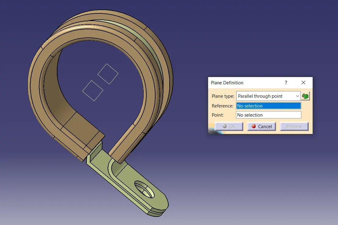
- Choose "Parallel through Point" on "Plane Type".
- Select "parallel surface" on "Reference" option.
- Select "point" on "point" option. Plane is created.
- Go to the "Part Design" workbench.
- Go to the "Reference" then choose "Plane" option.
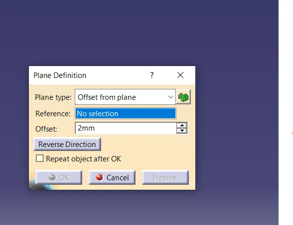
- Choose "Offset from Plane" on "Plane Type".
- Select "parallel surface" on "Reference" option.
- Give "Offest" value" of "2mm" then click ok.on "point". Plane is created.
c) DEFINE SUPPORT PART
- Open "Electrical Part Design" workbench.
- Go to the "Electrical Support Definition" then choose "Define Support Part".
- select the model or product name from tree.
- Name it the Select "point" and "plane" for "First Plane Definition" for Entry Case.
- Select second plane and base plane which is created.
- click on ok. Part is Electrically Defined.
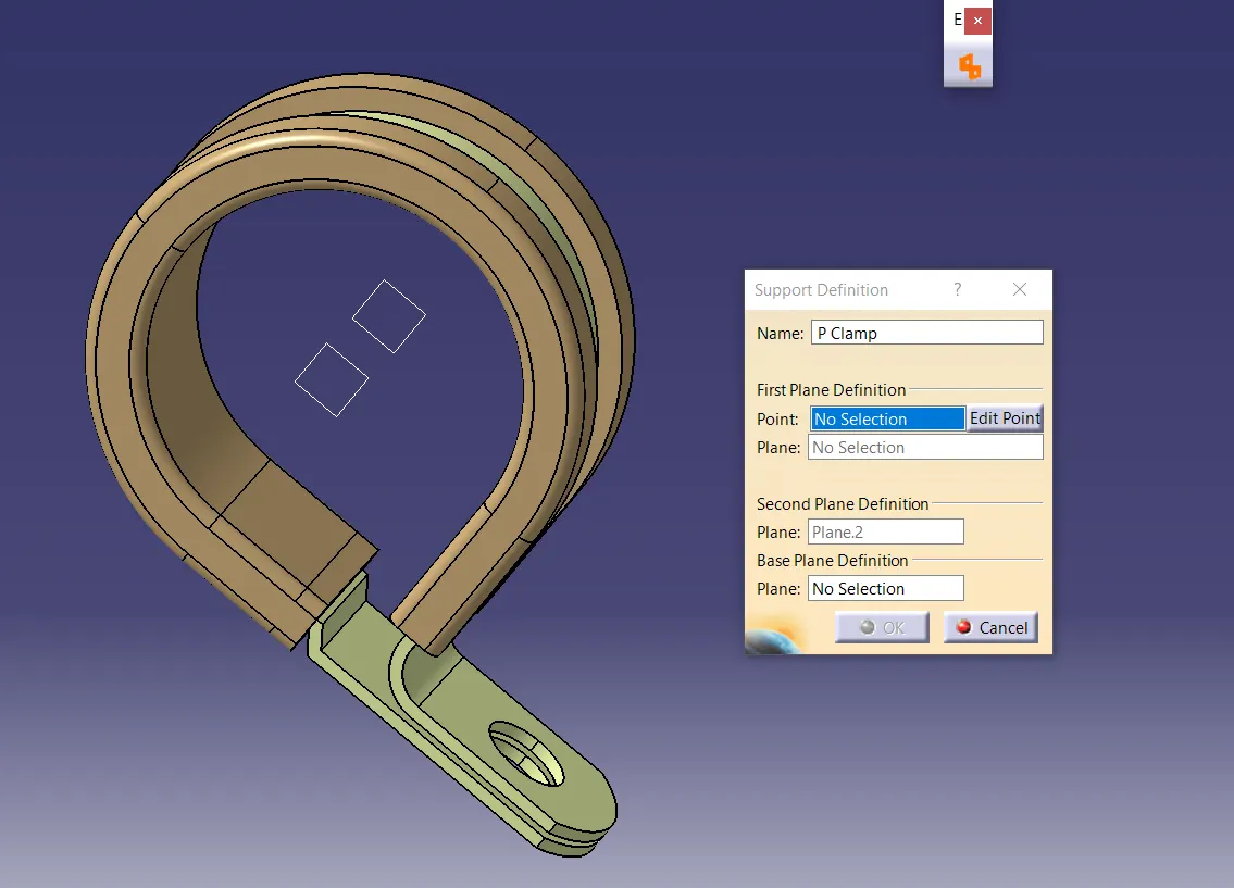
- Same follow for opposite side entry and exit.
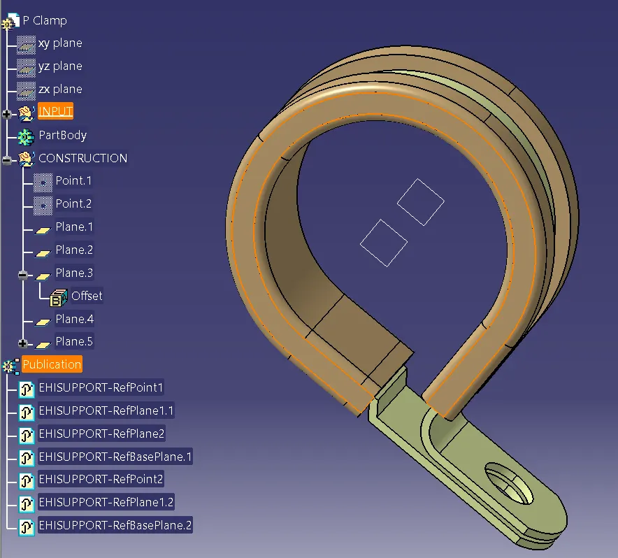
They typically have properties such as:
A) Material: P clamps are often made of materials like nylon, polypropylene, or metal, providing different levels of strength and durability.
B) Size and Diameter: P clamps come in various sizes to accommodate different cable or hose diameters. They are available in a range of sizes to fit specific applications.
C) Mounting: P clamps can be mounted using screws, rivets, or adhesive, offering flexibility in installation methods.
D) Temperature and Chemical Resistance: Depending on the material, P clamps can withstand different temperature ranges and resist chemicals, making them suitable for various environments.
E) Vibration and Shock Resistance: P clamps are designed to secure components even in environments with vibrations or shocks, ensuring the stability of the connected elements.
1. BACK SHELL
As for back shells, these are protective covers used in electrical connectors. Before Wire Harness routing, it is important to define it Electrical part Design Workbench. Important parameter required to define it Electrical Part Design-:
a) Entry Point & Exit Point
b) Plane
c) Define Support part
a) Entry Point & Exit Point
- Go to the "Part Design" workbench.
- Go to the "Reference" then choose "Point" option.
- Choose "Between" on "Point Type".
- Select point 1 and point 2 from corner then choose "middle point" option.
- Entry point is created automatically.
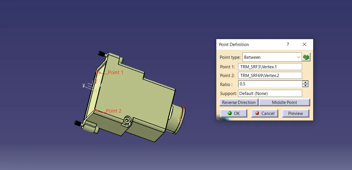
- Go to the "Part Design" workbench.
- Go to the "Reference" then choose "Point" option.
- Choose "Circle/Sphere/Ellipse center" on "Point Type".
- Select circle and Exit point is created automatically.
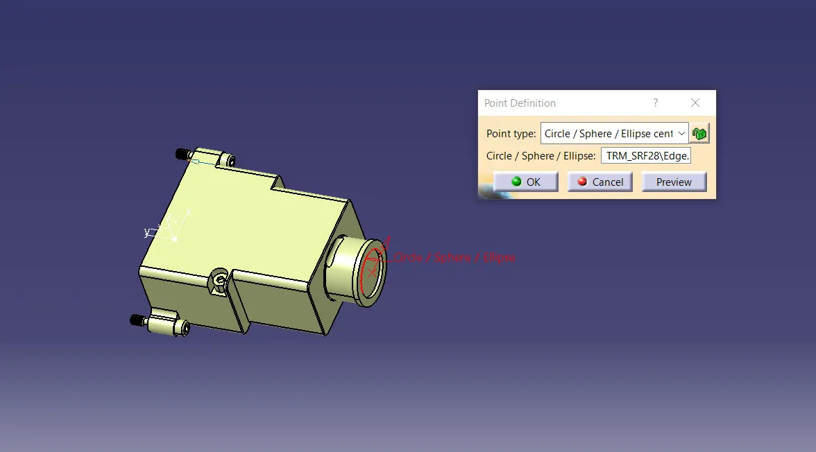
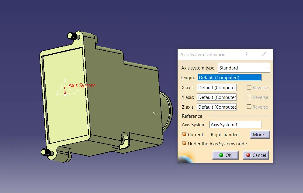
b) AXIS
- Go to the the "Axis" command on "Tools" option.
- Click on "point" in "Origin" option.
- Rotate it and set the "x, y and Z" direction as per required.
- Then click on ok. Axis is created.
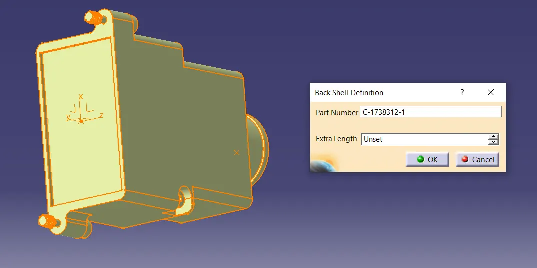
c) Define as Electrical Part
- Open "Electrical Part Design" workbench.
- Go to the "Electrical Device Definition" Option.
- Edit "Part Number" or left it as it is.
- Choose "Unset" option on "Extra Length".
- Click on ok.
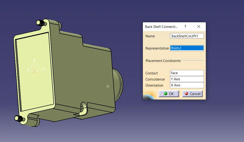
- Go to the "Electrical Point Connection Definition" option.
- Select "Back Shell Connection" Option.
- Name it then select "point" on "Representation" option.
- Select "Face" on "Contact" option then select "Y axis" as "Coincidence.
- Then Select "X Axis" in "orientation" option. then click on ok.
- This Back Shell is Electrically defined.
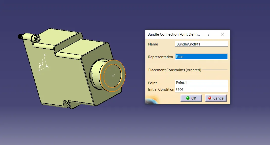
- Go to the "Electrical Point Connection Definition" option.
- Select "Bundle Connection Point Definition" Option.
- Name it then select "Face" on "Representation" option.
- Select Another side "Point" on "Point" option.
- Then again select "Face" on "Initial Condition" option. Then click on ok.
- The Bundle Connection Point is Electrically defined.
Their properties include:
A) Material: Back shells are often made of metal or plastic, providing shielding and protection against electromagnetic interference.
B) Connector Compatibility: Back shells are designed to fit specific connector types, ensuring a proper and secure fit.
C) Cable Entry: Back shells have various cable entry options, such as strain relief clamps or grommets, to secure the cable and prevent it from bending or pulling out of the connector.
D) EMI/RFI Shielding: Metal back shells are effective in providing electromagnetic interference (EMI) and radio frequency interference (RFI) shielding, essential in sensitive electronic applications.
E) Durability: Back shells are engineered to withstand environmental factors such as moisture, heat, and mechanical stress, ensuring the longevity of the connectors and cables they protect.
3. CORRUGATED TUBE
Corrugated tubes, also known as flexible corrugated conduits or pipes, are designed with a series of ridges and valleys on their surface, resembling a corrugated pattern. This design provides them with flexibility and makes them ideal for various applications, such as protecting electrical wires, cables, or fluid-carrying systems.
The corrugated structure allows these tubes to bend and flex easily without compromising their structural integrity. They are commonly used in situations where standard rigid pipes or conduits are impractical due to the need for flexibility or when the installation environment requires movement or vibration resistance.
Corrugated tubes are widely used in industries such as automotive, construction, telecommunications, and electronics, providing protection and organization for wires and cables in challenging environments.
CREATE "Slit COT" CATALOGUE
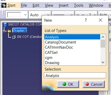
- Go to the "File" then "New" then open "CatalogDocument" workbench.
- Name it.
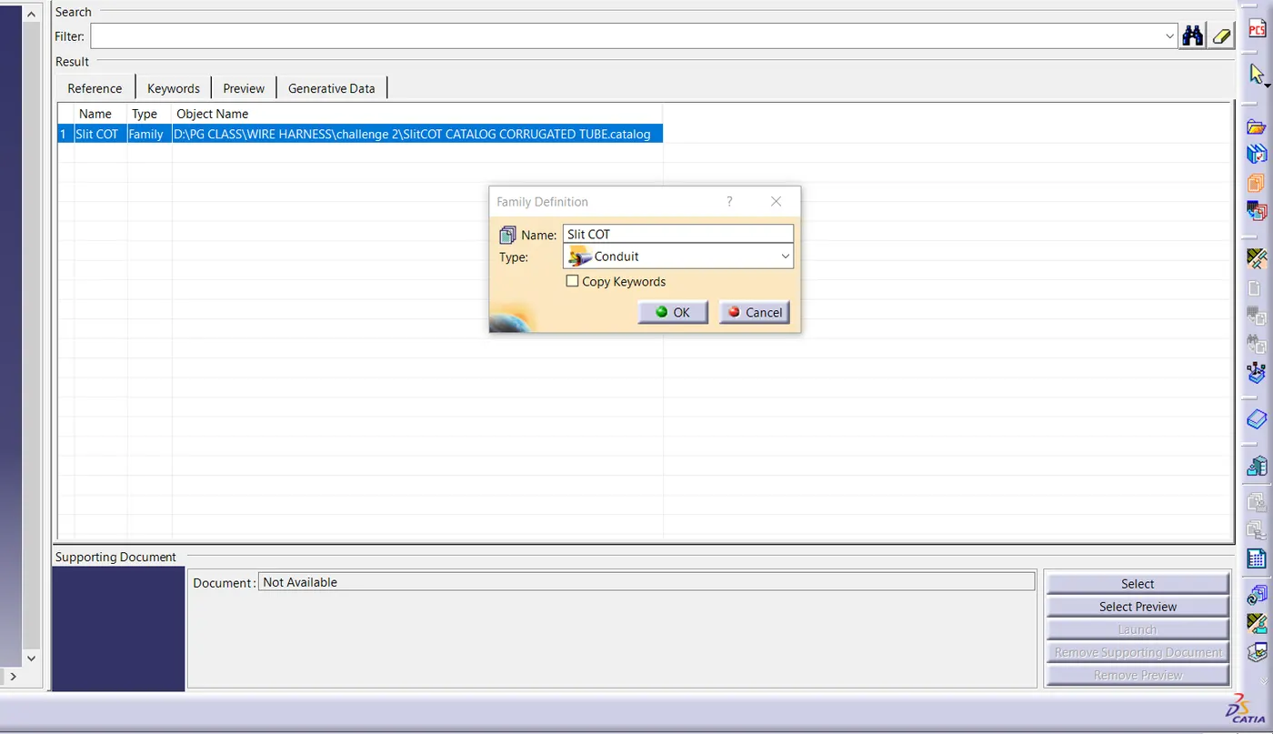
- Choose "Add Family" option.
- Name it as "Slit COT".
- On "Type" option, choose "Conduit".
- Select "Slit COT" name, which one is created earlier.
- Go to the "Add Part Family" option.
- Name it as "Part Family1" then choose "Conduit" on "Type" option.
- Then save the file.
1. CREATE CORRUGATED TUBE
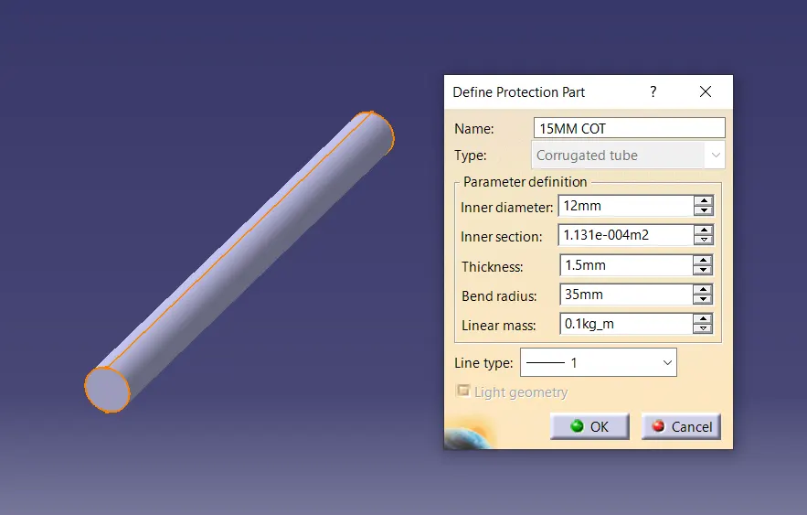
- Open the "Electrical Part Design" workbench.
- Go to the "Define Protection Part" file option.
- Select the "Product name" from "Feature tree".
- Give the name as "15MM COT"
- Choose "Corrugated tube" option on "Type".
- On the "Parameter Definition, Put the value of "Inner diameter" as "12mm".
- Inner section value left it as it is.
- Give the "Thickness" value and "Bend Radius" value and "Line Type" choose 1.
- Then Click on Ok, Corrugated Tube is created automatically.
2. STORE CORRUGATED TUBE IN CATALOGUE
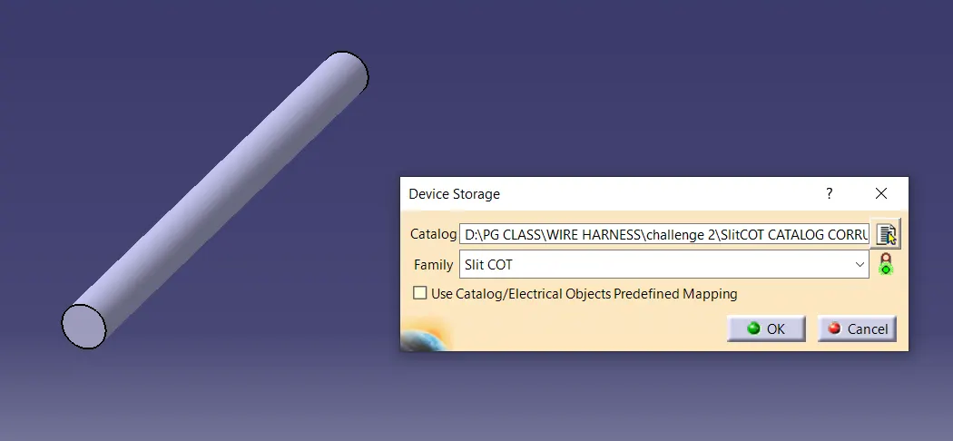
- Save the Corrugated tube file.
- Then go to the "Store Devive" option.
- Select the path, where the "Catalogue file" is saved earlier in "Catalg" option.
- Select "Slit COT" option on "Family".
- Then click on Ok. Corrugated tube is saved in Catalogue automatically.
- FOLLOW 1 AND 2 ALL STEPS TO CREATE ALL OTHER CORRUGATED TUBE.
- NAME IT AND PUT ALL VALUE AS PER REQUIRED.