Wiring harness routing & packaging Rules Week 3 Challenge
AIM:
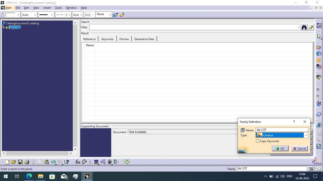
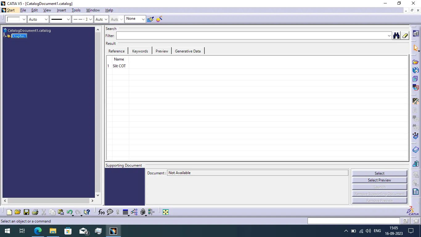
To define the P clamp as a electrical support component and define the back shell as a electrical back shell and defines it's necessary properties. And create the Corrugated tubes with given geometrical data and add them in Catalogue under "Slit COT" family.
P CLAMP:
Required defining parameters:
- Entry point and plane
- Base plane
- Exit plane
Support part define process:
- P Clamp is the support part used in the automative wiring harness assembly.
- First we want to create the required points and planes using part design workbench.
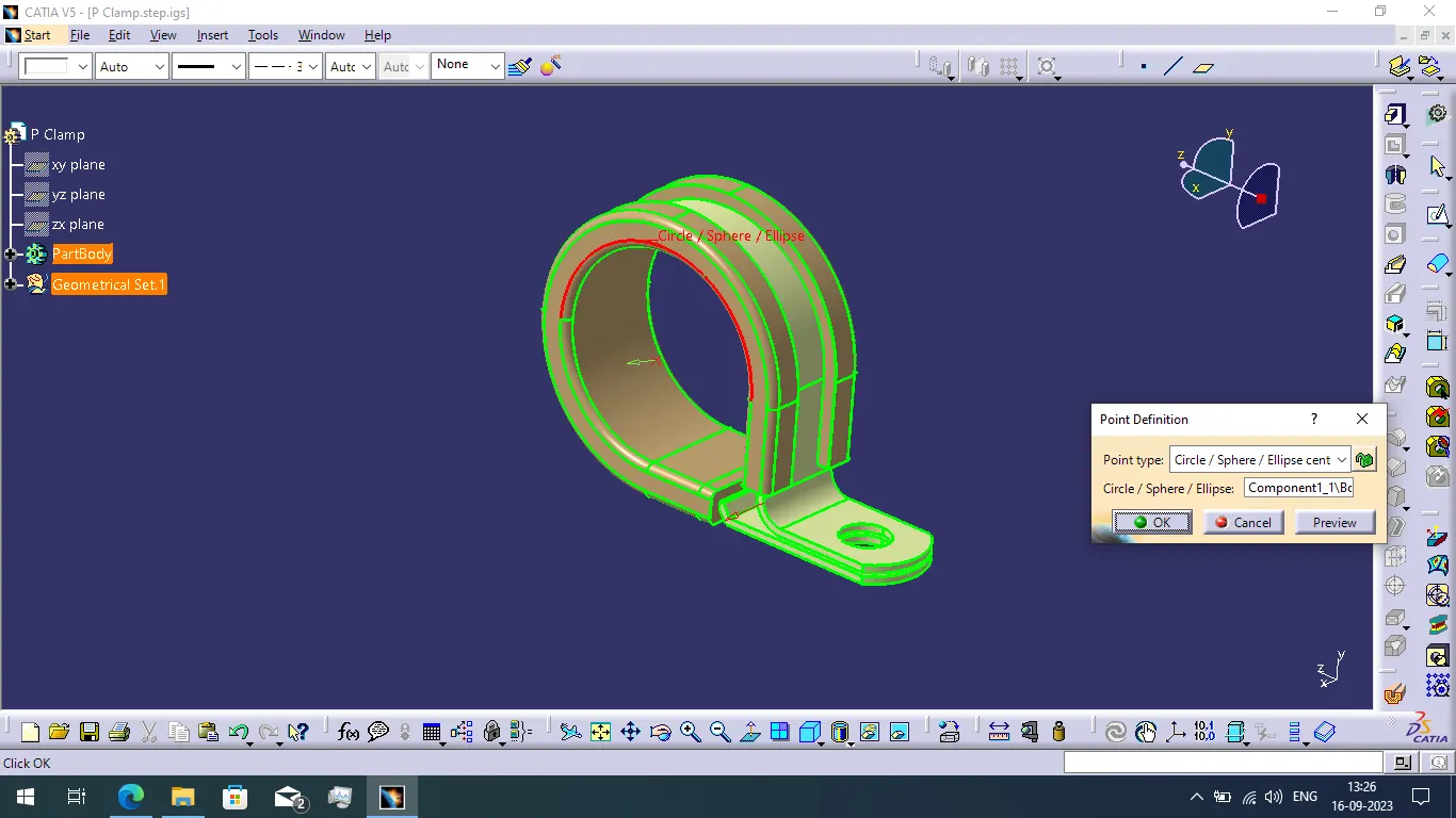
- In first create the two points using the circle center point type method.
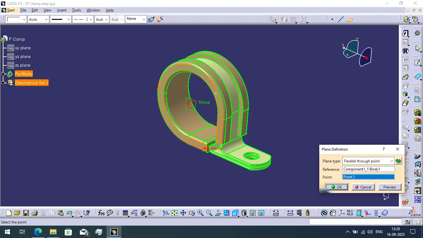
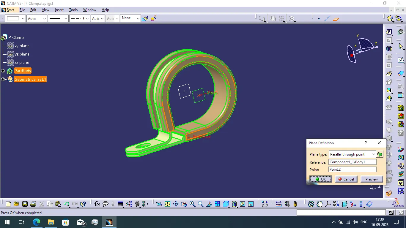
- Next we create two planes with help of created two points using parallel through point type of plane.
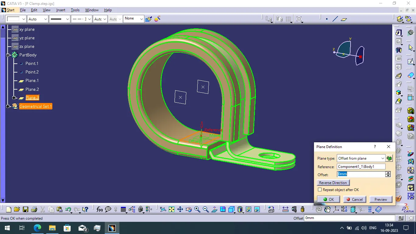
- Now create the third plane using the surface of the P Clamp for offset from plane method.
- Now switch the part workbench to electrical part design workbench and define the P Clamp as a support part.
- When we try to define the support part their is two way of entry and exit during the harness assembly. So we want to define two paths of entry and exit.
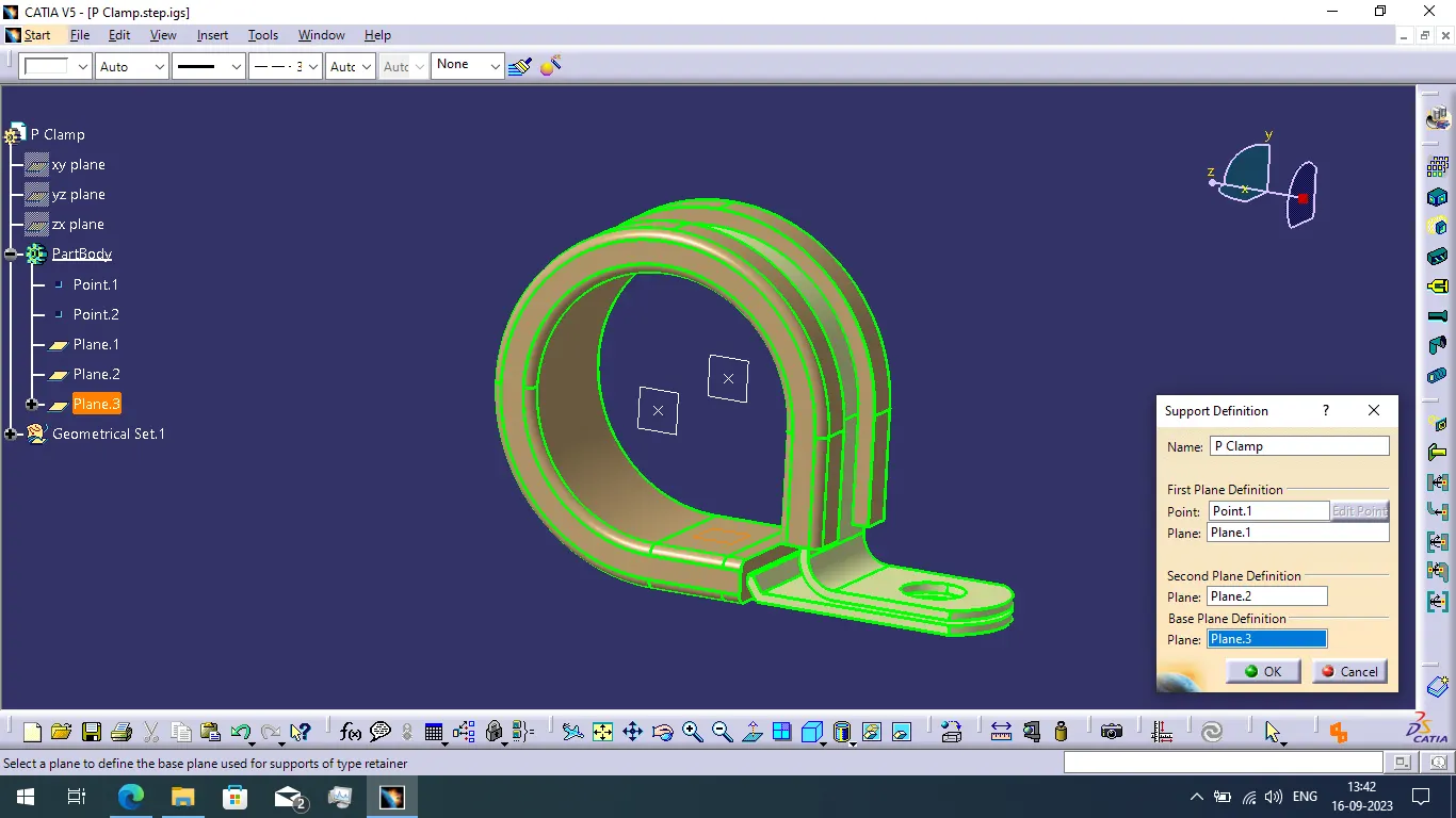
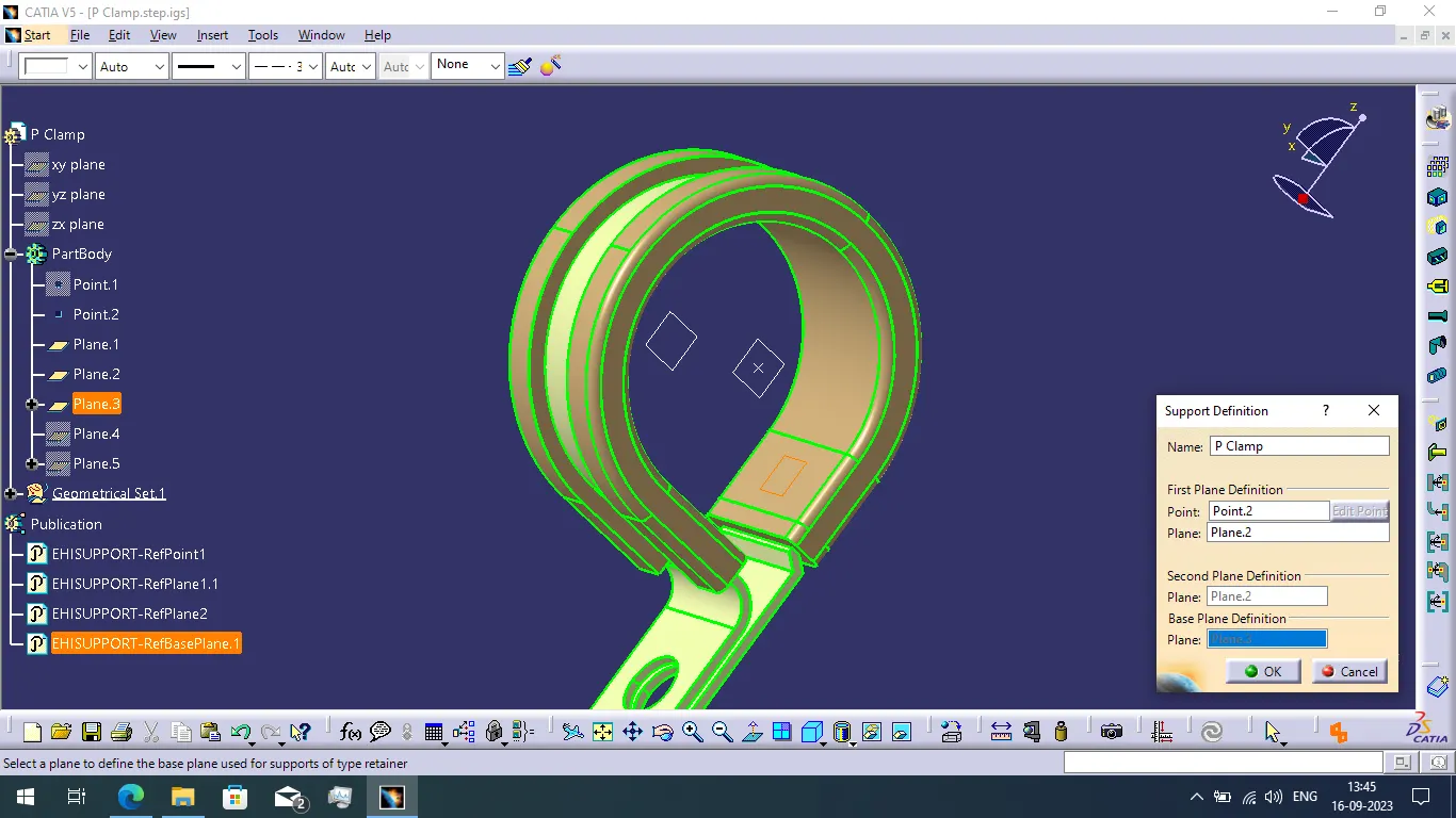
- Finally we completed to define the support part.
Properties of P Clamp:
- It helps to lock cables and hoses in place.
- It helps to ensure the machinery, vehicles and equipment keep running.
- They bracket wires, cables or hoses together mechanically and are fastened securely to an anchor point, usually with a screw or a bolt.
BACK SHELL:
- Back shells are plastic molded parts used at wire entry side of connectors either for protection or to improve aesthetic/appearance of harness.
- This is not a manetory part of wiring harness.
Defining the backshell:
- In first we want to define the required geometrical parameters of points and axis system.
- We want to create the bundle connection point and backshell connection point using part design workbench.
- Create the bundle connection point using between point method.
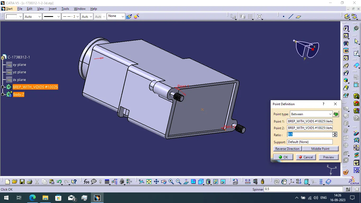
- When completing to create the bundle point then next we create the backshell connection point using circle center point type method.
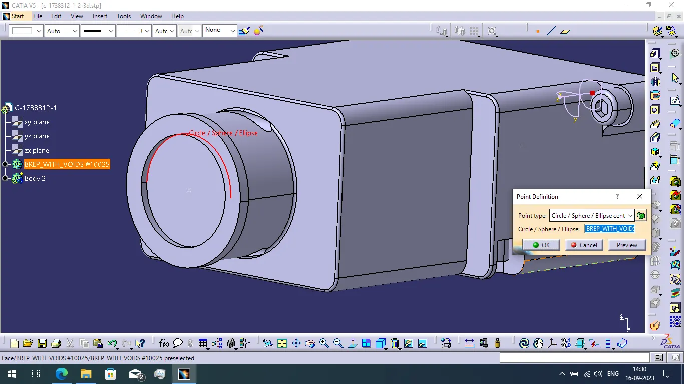
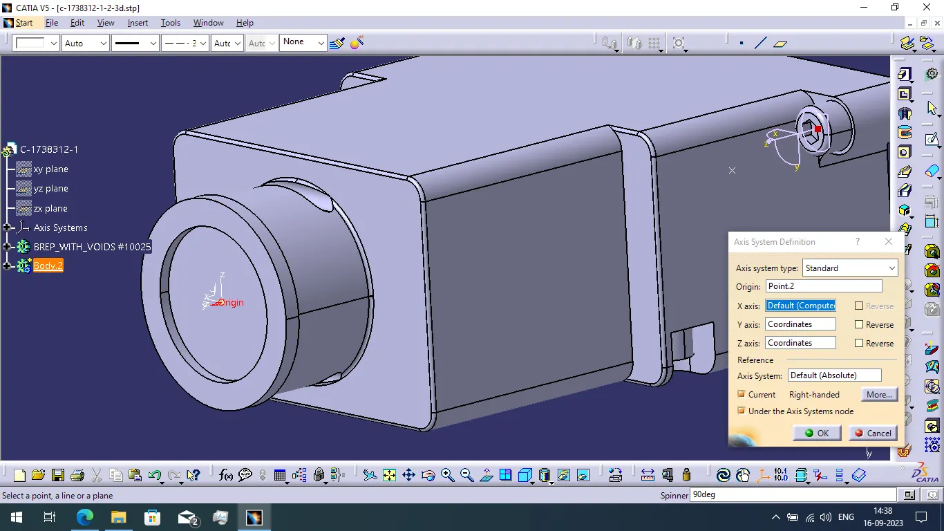
- Then we create the axis system using backshell connection point. When creating axis system consider the contact face, coincidence direction and orientation direction.
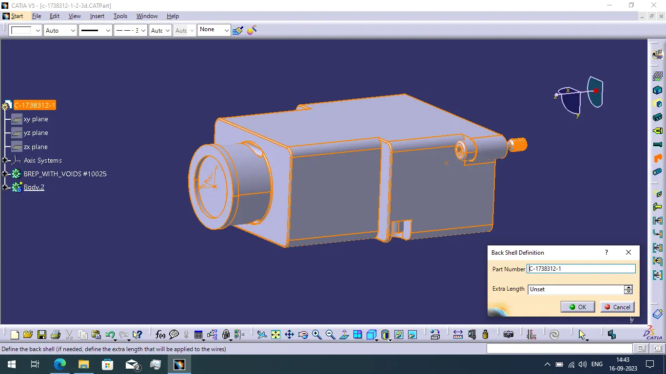
- Now switch the workbench part design to electrical part design. Then define component as a backshell.
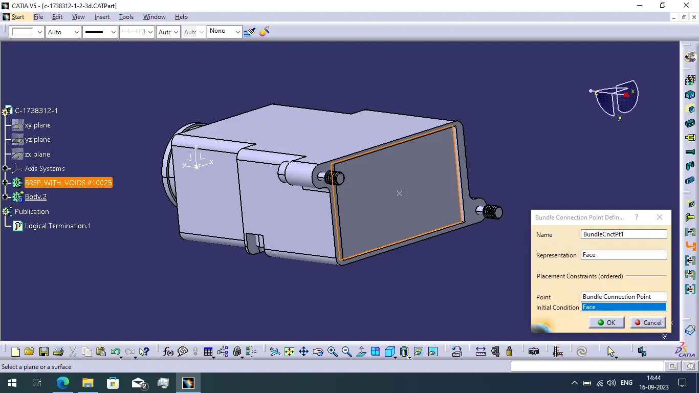
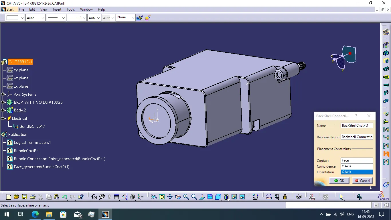
- Next we want to define the bundle connection point and Backshell connection point.
CORRUGATED TUBES:
- if we created the catalogue and add the files in catalogue.
COT 15mm:
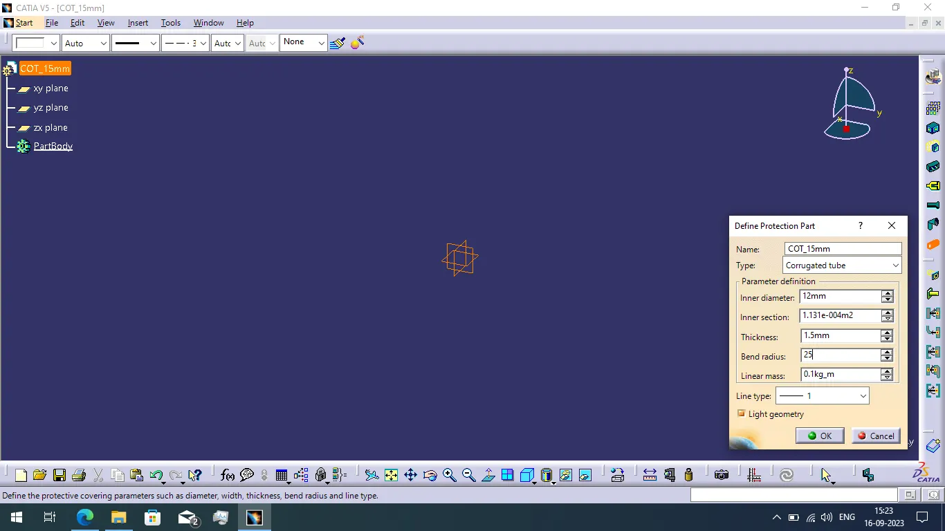
- Now create the new part file with the name of Corrugate tube diameter basis.
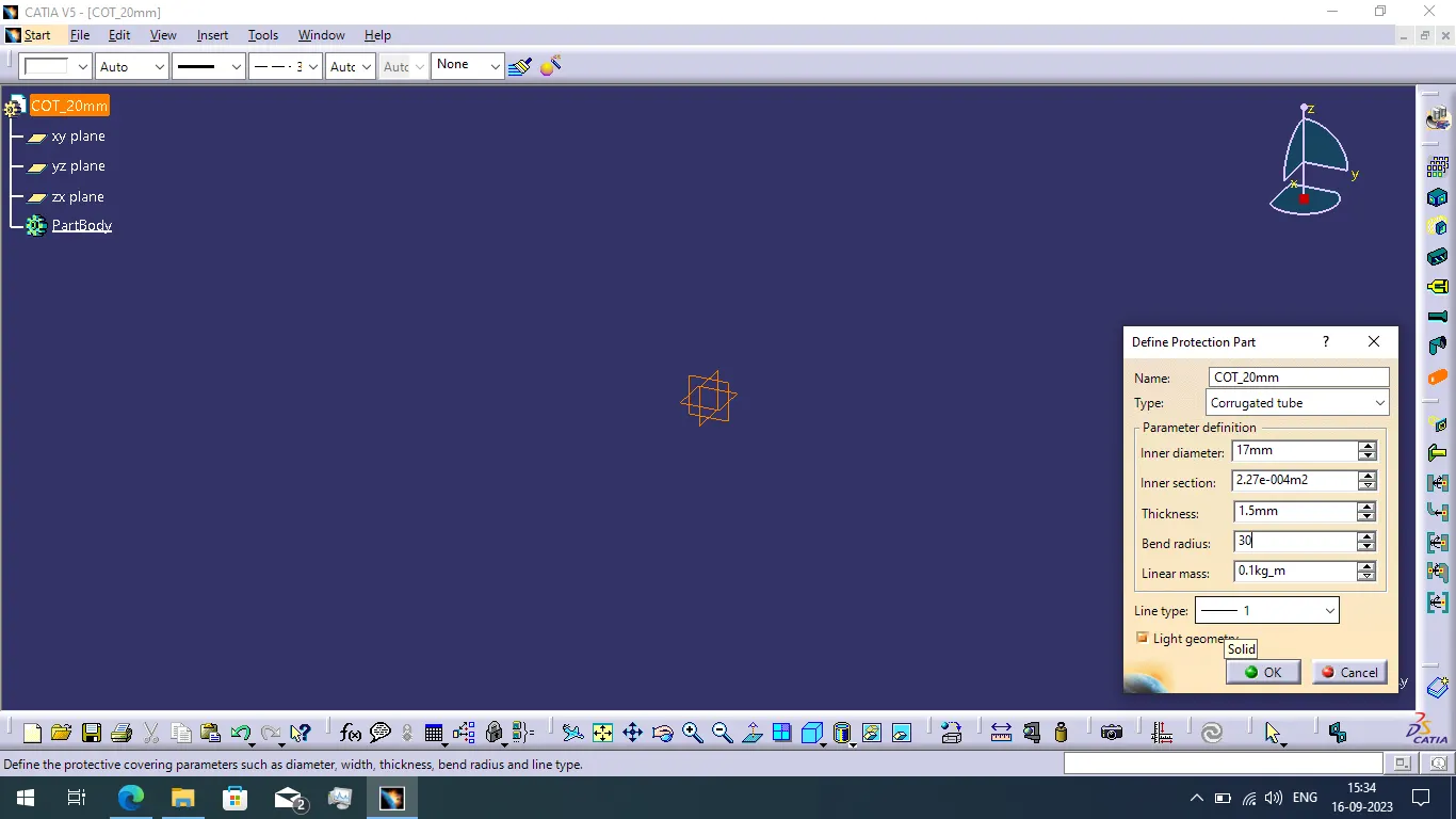
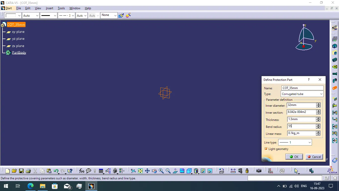
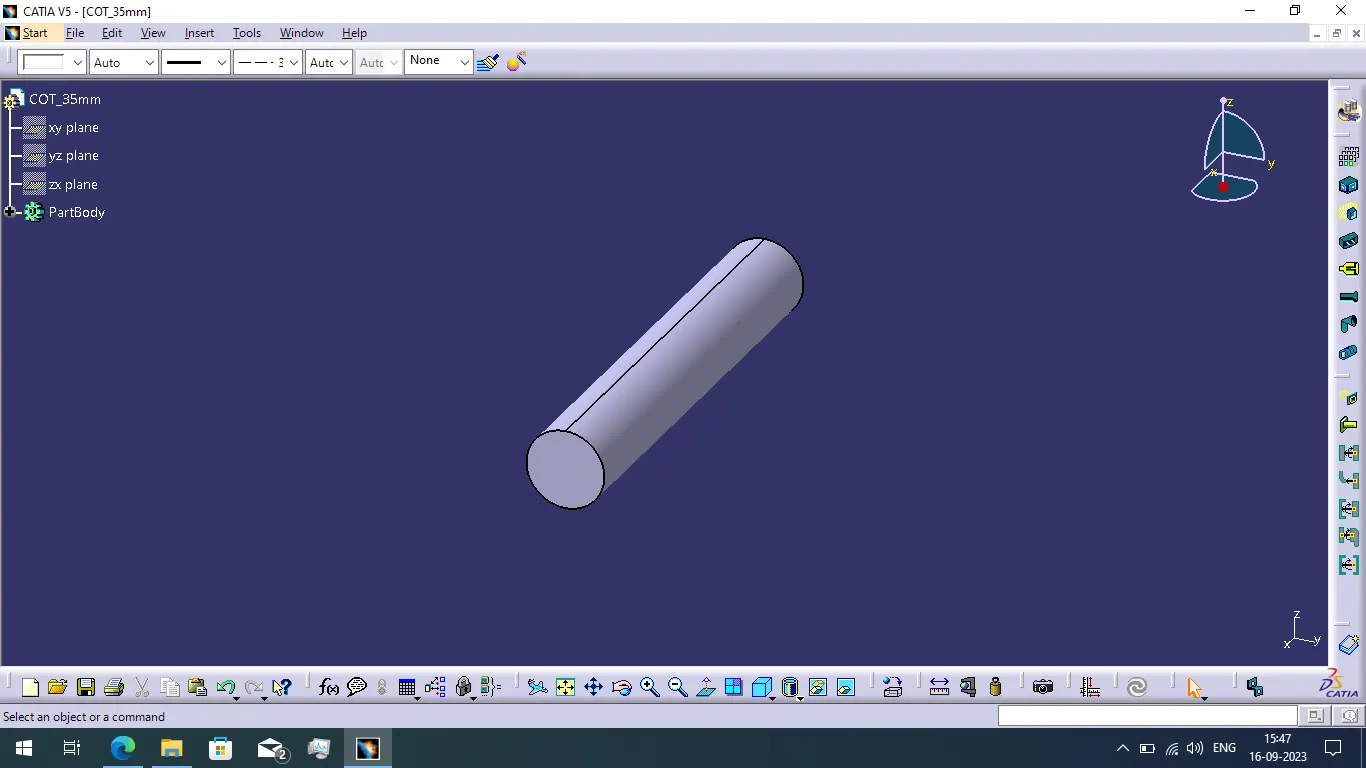
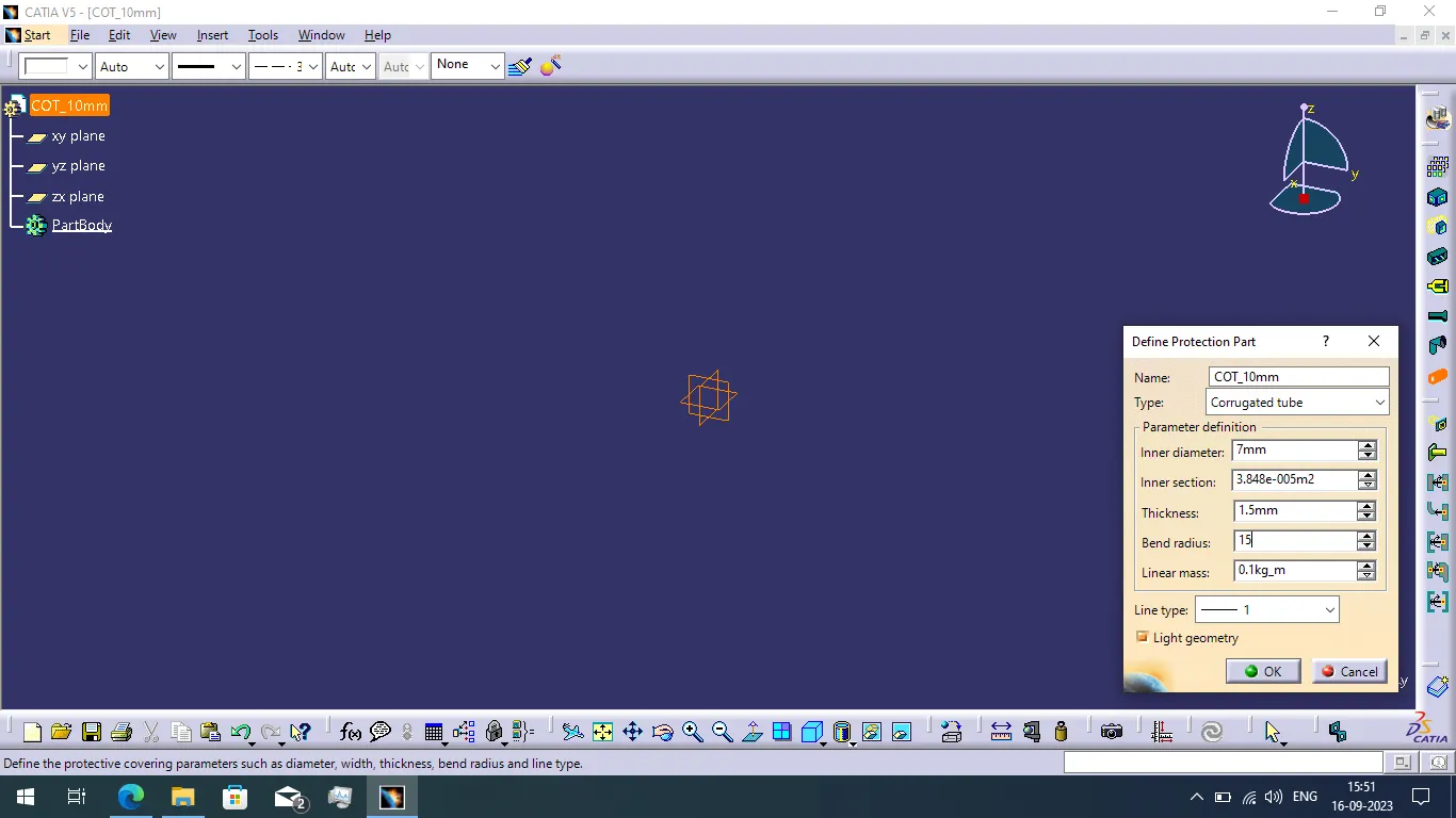
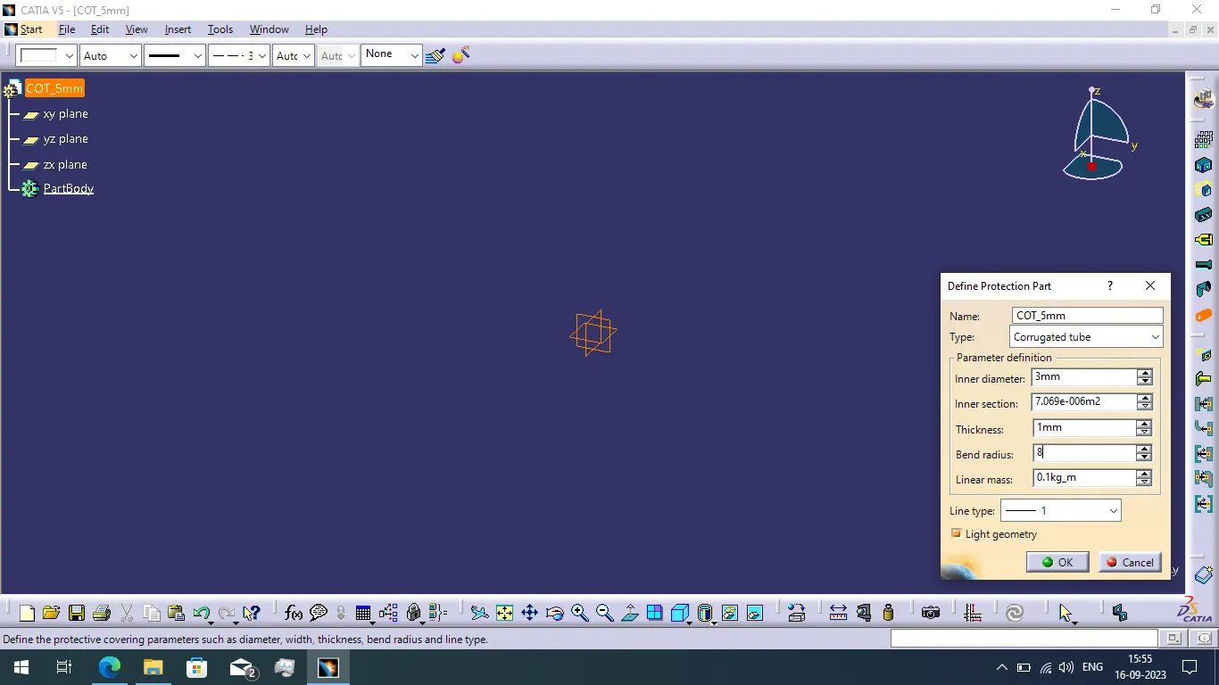
- Then use the define protection part command and select the file body then give the required dimensions to create the corrugated tube.
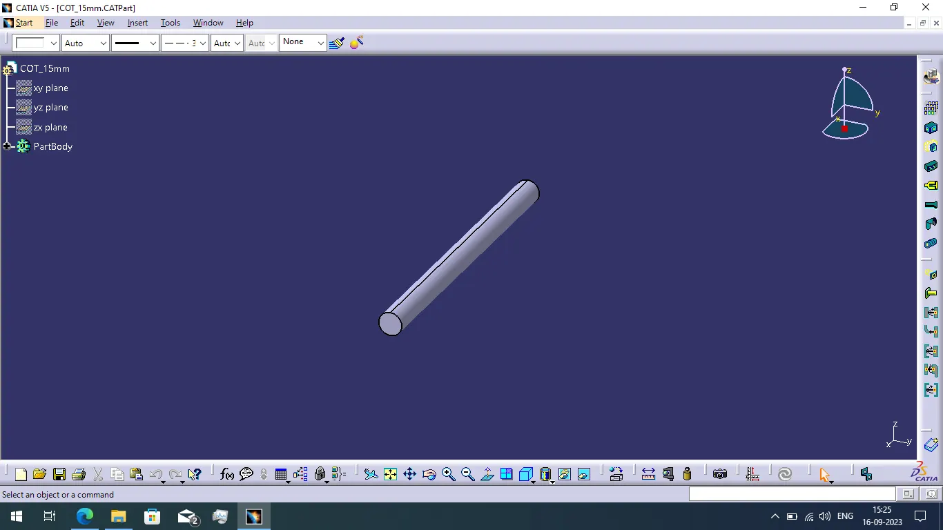
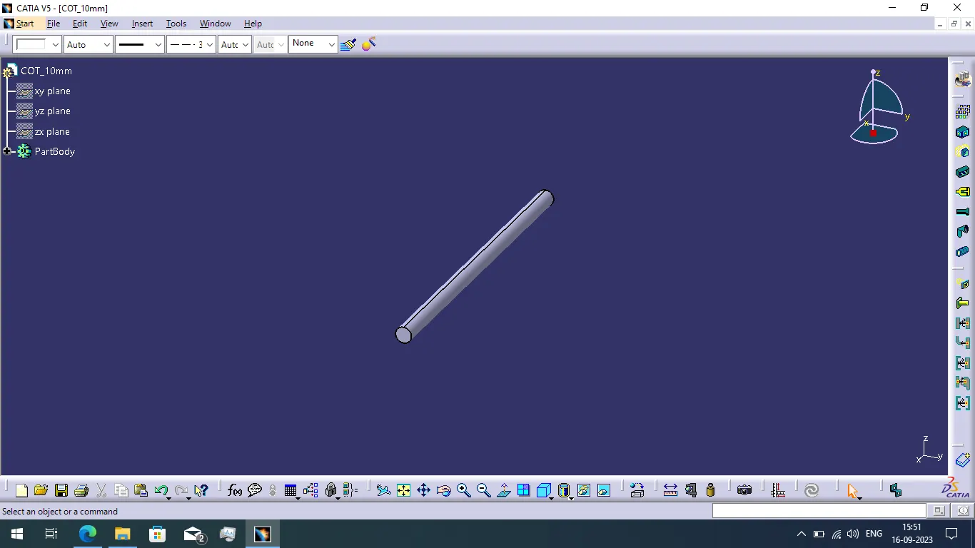
- After created the corrugate tube save the file and select the store device option and add the file into the catalogue.
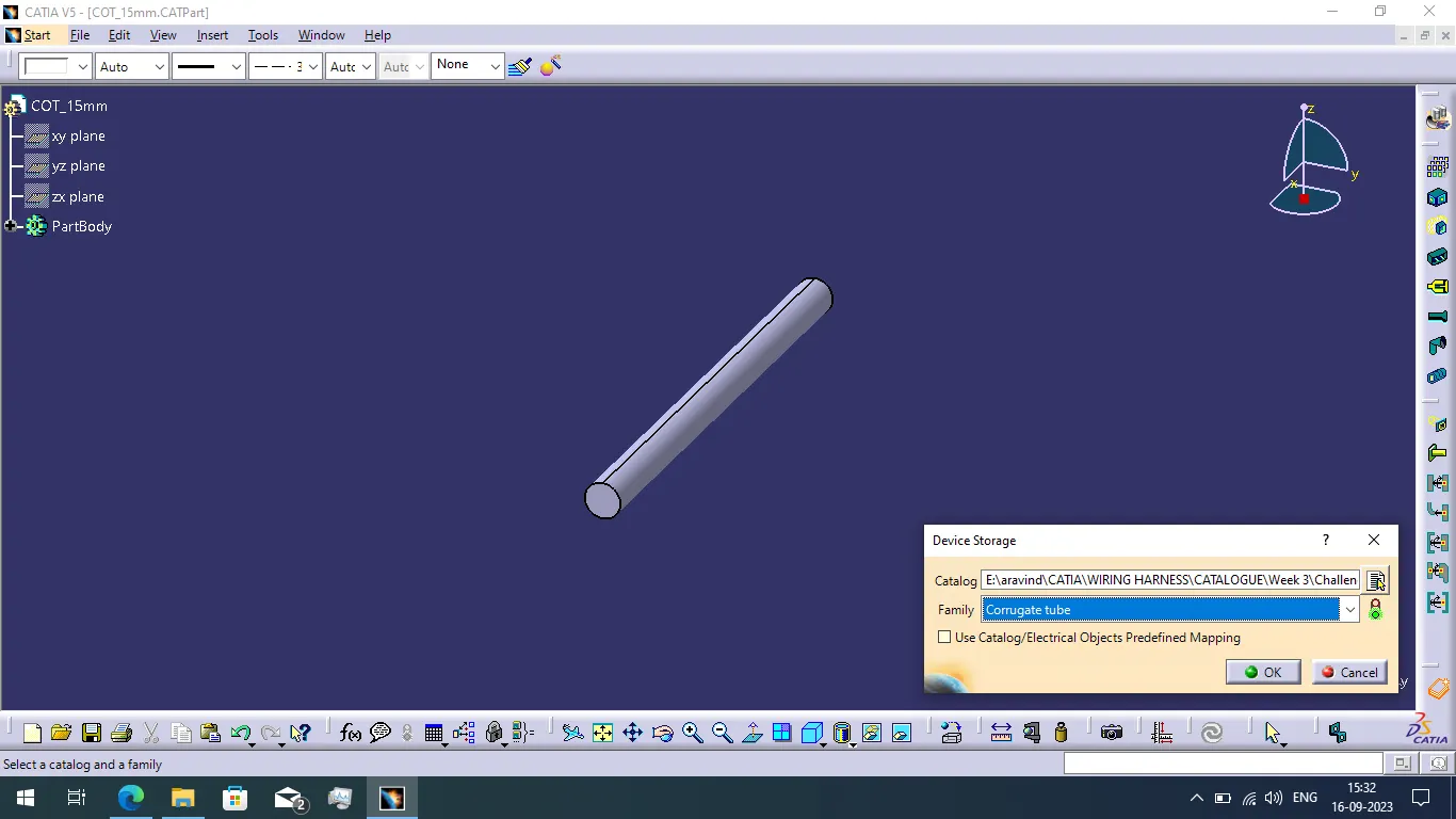
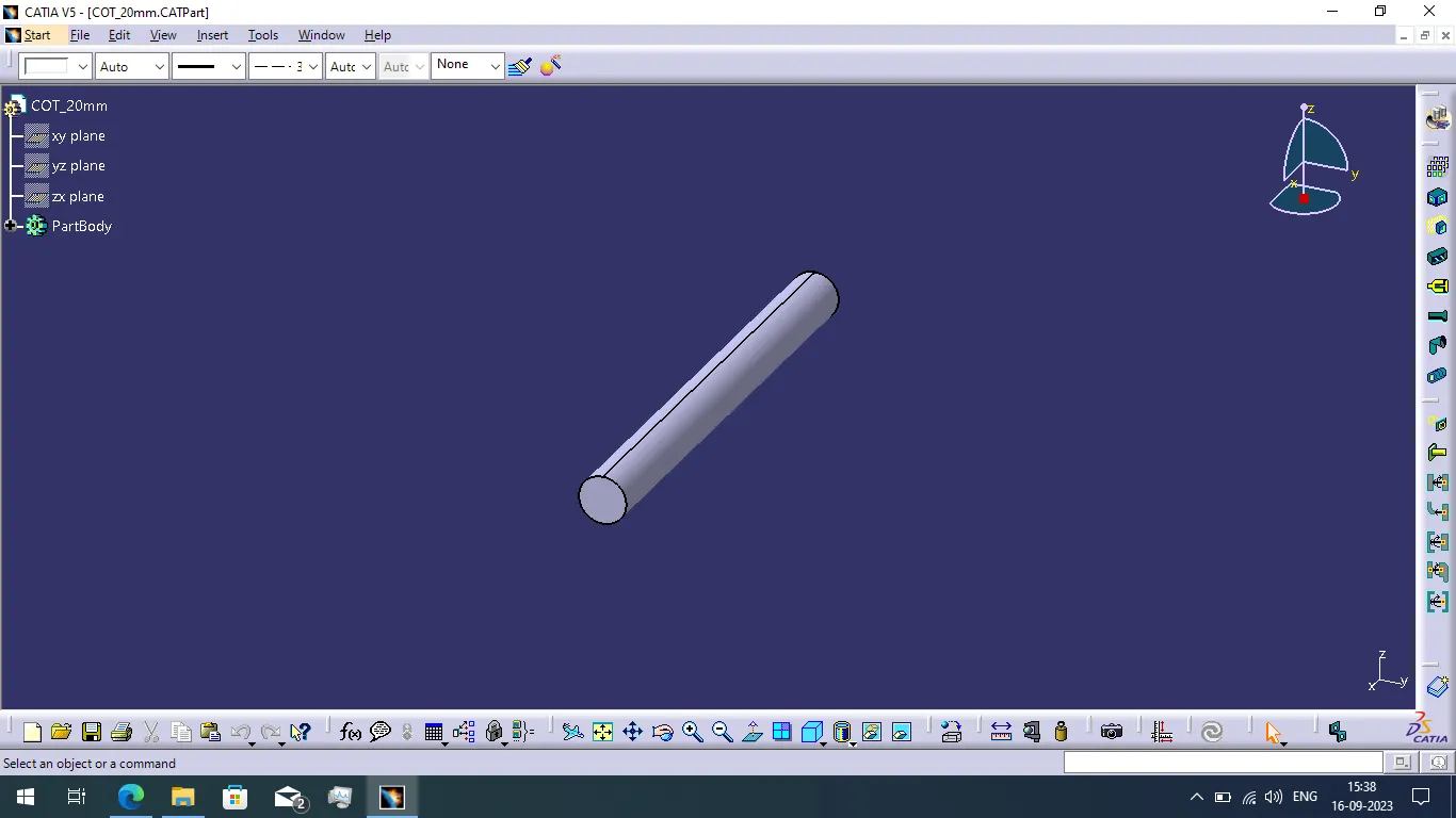
- Use the similar step to create the corrugated tube of different dimensions and add the file into the catalogue.
COT 20mm:
COT 35mm:
COT 10mm:
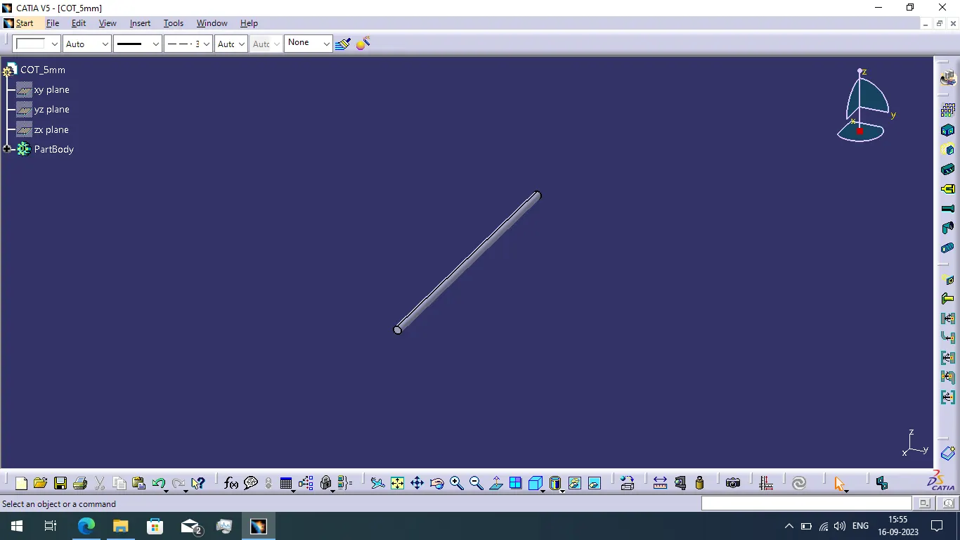
COT 5mm:
CONCLUSION:
Finally i completed to defined the P clamp as an electrical support part and define the Backshell as an electrical part and create the corrugated tubes with given dimensions and add all the corrugated tubes to catalogue file.