Wiring harness routing & packaging Rules Week 3 Challenge
Report
Aim:-
Introduction
Wiring harness
A wire harness, often referred to as a cable harness or wiring assembly, is a systematic and integrated arrangement of cables within an insulated matrial. The purpose of the assembly is to transmit signal or electrical power. Cables are bound together with straps, cable ties, cable lacing, sleeves, electrical tape, conduit, or a combination thereof. The wire harness simplifies the connection to larger components by integrating the wiring into a single unit for “drop-in” installation. A wiring harness consists of different sets of connectors like terminals and wires which run through the entire vehicle and transmit information.
A wire harness process is designed based on the geometric and electrical requirements of the equipment it is to be installed in. Once the initial design is established, a schematic is used to create the manufacturing paperwork and the assembly board for the harness. The assembly board, also called a pin board, is a full-size diagram of the harness that shows all of the components and their locations. It also serves as the workbench for the harness.
Clips
Clips are ideal elements for retaining / holding pipes, cables, cable harnesses, hoses etc. Clips act as form fitting adjustable bands for ease of assembly & installation. The band ends of the clips are reinforced to prevent any tearing or loosening due to high mechanical loads. ‘P’ clips are fitted with EPDM liners which help achieve a tighter grip on the cable / conduit & also act as dampeners for sound & vibration.
Back shells
A back shell is a mechanical device threaded into the rear of an electrical connector and is designed to provide screening, sealing, and reparability. Engineered to help resist corrosion and fit a wide range of circular connectors, back shell components help protect connections from mechanical wear, environmental conditions, and electromagnetic interference (EMI). These are available with and without screen termination, providing long-term, high performance in sealed and unsealed electronics systems.
Corrugated tubes
Corrugated tubes made from flame-retardant material these tubes will protect cables from impact and abrasion. They are highly flexible and have a high fatigue life, making them ideal for any installation. Depending on the intended use, corrugated tubing is manufactured in different diameters and from different materials. Even though these are usually rigid materials, convoluted plastic tubing becomes flexible and bendable due to its corrugated manufacturing method.
Q1. Download following clip cad data & define it as Electrical support using Electrical Part design Workbench. Define all the necessary properties.
Hellarmann Tyton – 21160129
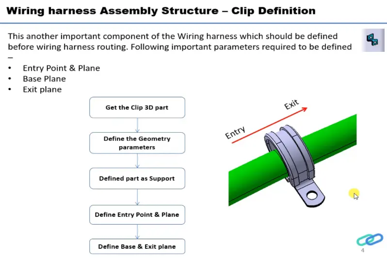
process:
- Create two points one as entry and another as exit point.
- create planes at two points and another at base.
- Switch to Electric part desgn
- Click on support defination - select part - select entry point - select entry plane, exit and base plane.
- Again Click on support defination - select part - select exit point - select exit plane and base plane as secondary plane is automatically taken.
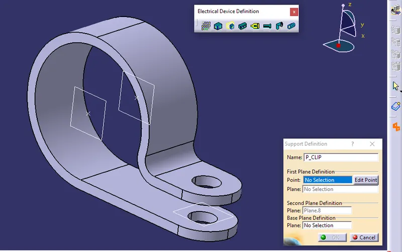
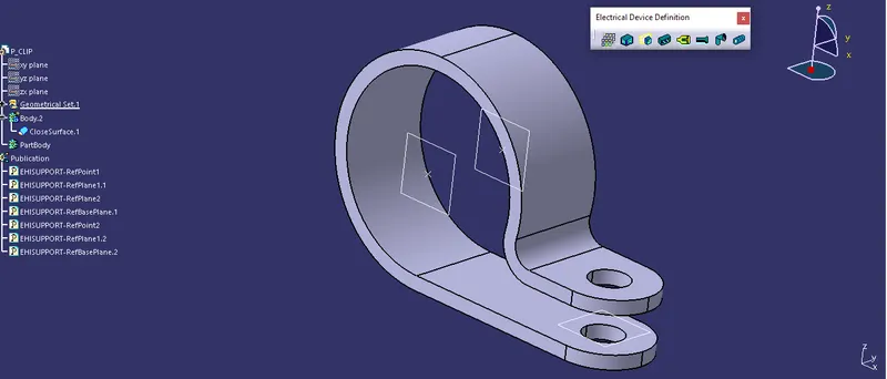
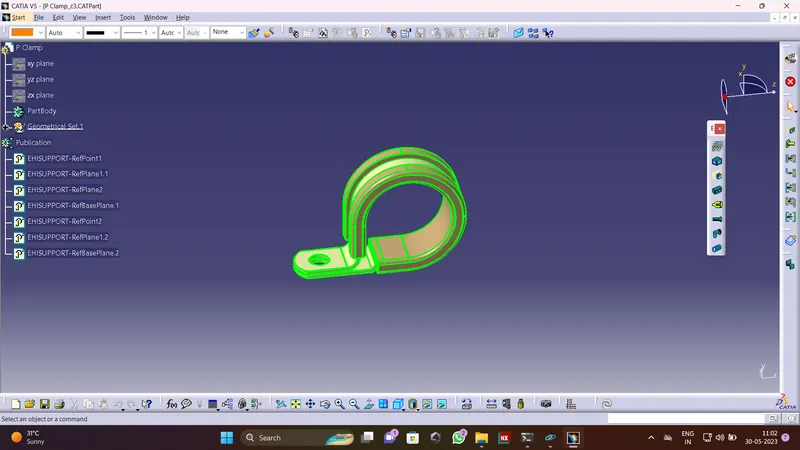
Aim:-
Q2. Download the following Back shell cad data & define it as an Electrical back shell using the Electrical Part Design Workbench. Define all the necessary properties.
Tyco 1738312-1 https://www.te.com/usa-en/product-1738312-1.html
Solution:-
Defining the Backshell -
- Get the Backshell 3D part
- Define the Geometry Parameters
- Define part as Backshell
- Backshell connection point
- Define Bundle connection point
Mechanical Part Design Workbench
- Define the Geometry Parameters
Points and Axis system -
Defining the points through point definition for bundle entry and mating sides.
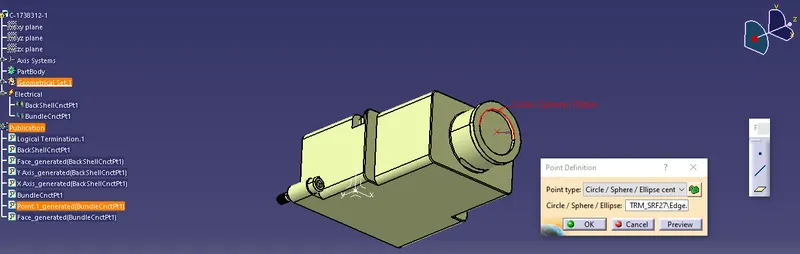
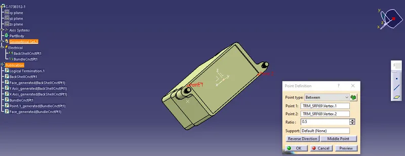
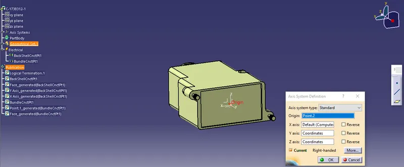
Defining the axis system for the mating side, where the y-axis is in the mating direction, the x-axis to the side, and the z-axis is directed upward.
Electrical Part Design Workbench
- Define part as Backshell
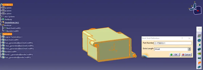
Part is defined as backshell using the back shell definition command.
Steps followed
- Download the neutral data file (step file / igs file) of the back shell from the given source (TE connectivity website) and open it in the CATIA part workbench.
- Study the back shell model and understand the faces of the back shell connection point, bundle connection point and mechanically locking sides.
- Create the geometries like center points of back shell connection point, and bundle connection point by selecting appropriate edges and create an axis on the back shell connection point with respect to the same axis direction of the compatible mating part by placing the Y axis towards back shell connection point (mating point) direction and the X axis pointing towards the side of the locking mechanism.
- Now switch to the electrical part design workbench and define the model as an electrical back shell part by using the define back shell command.
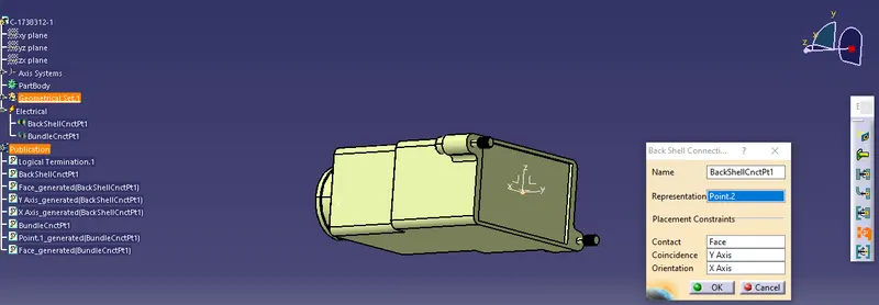
- Define the back shell connection point by giving the representation as the back shell connector point, selecting the face of contact, coincidence direction as Y axis and orientation direction as X axis.
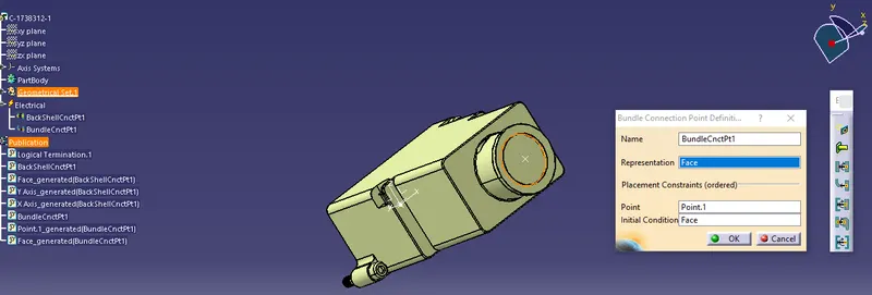
- By using the define bundle connection point command available in the electrical part design workbench and by selecting the face of the bundle entry side and the created bundle center point define the bundle connection point of the back shell.
- Now the back shell part file is converted into the electrical part file with all electrical properties.
- Backshell connection point
- Define Bundle connection point
3) Create different corrugated tubes as per the given data and add them to a new catalog
- Read and understand the given data file of different types of corrugated tubes by their name, inner diameter, outer diameter and thickness. Then calculate the bend radius of the corrugated tubes with respect to their outer diameter.
- The bending radius of standard corrugated tubes will be 1.5 times to its outer diameter. By using this method, the bending radius of each corrugated tube is calculated.
- First we have to create a new catalog named as “Slit COT” by creating a new file and model as a new catalog document then use add family option available in the popup screen by giving the desired name (Slit COT) and type as conduit save the catalog to the desired location with a proper file name.
- Now switch to the electrical part design workbench and go to the define protection part command a pop-up window will appear to select the type as corrugated tube and give the appropriate inner diameter, thickness, bend radius as per the given input data and adjust the line type if required. Always keep a light geometry profile for protective coverings like corrugated tubes and insulation tapes.
- After creating the corrugated tube add each file to the saved catalog “Slit COT” using the command store device and by selecting the appropriate catalog and family.
- Follow the same steps for creating different types of corrugated tubes and saved them to the catalog so that we can use them for further operations.
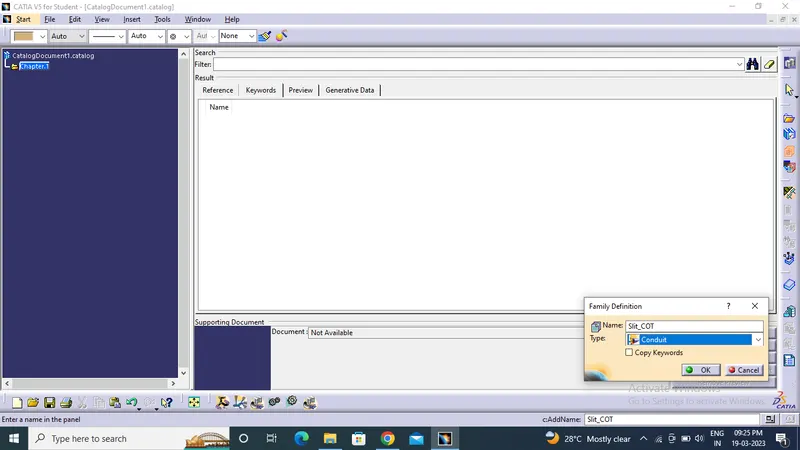
New catalog named as “Slit COT” by created by giving desired name (Slit COT) and type as conduit
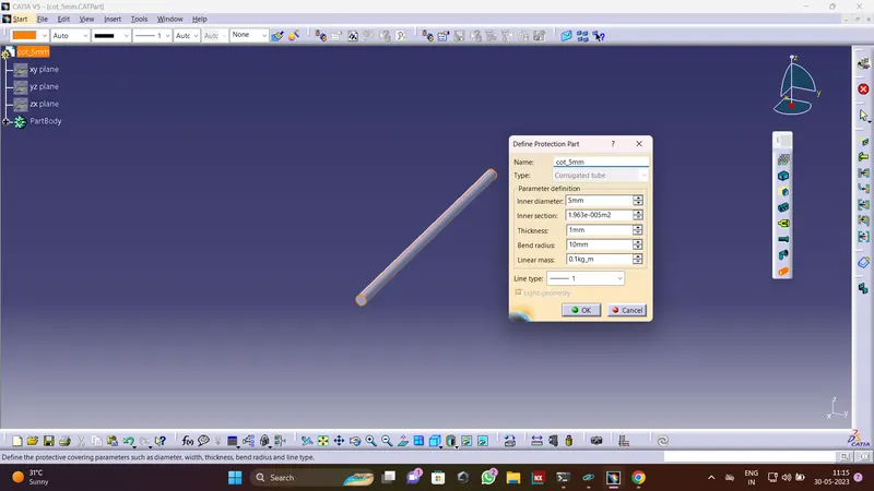
In electrical part design workbench and go to the define protection part command a pop-up window will appear to select the type as corrugated tube and give the appropriate inner diameter, thickness, bend radius as per the given input data and adjust the line type if required. Always keep a light geometry profile for protective coverings like corrugated tubes and insulation tapes.
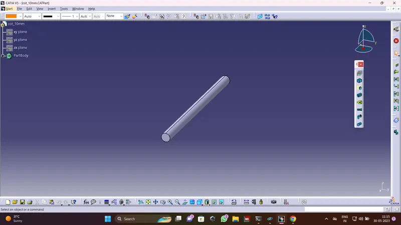
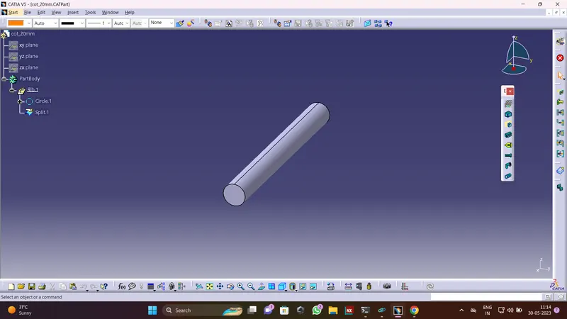
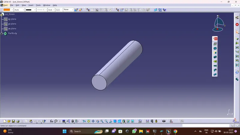
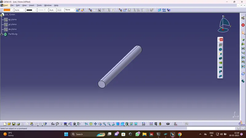
Saved corrugated tube files to catalog “Slit COT” using the command store device and by selecting the appropriate catalog and family.
Follow the same steps for creating different types of corrugated tubes and saved them to the catalog so that we can use them for further operations.
Conclusion
The cad part model the of P-clamp is converted into the electrical support model, back shell into the electrical back shell and create different corrugated tubes as per the given data and add them to a new catalog thereby understand the methods follow to create and convert the catalog, corrugated tubes, clips, back shells, and wiring harness routing and packaging rules.