Wiring harness routing & packaging Rules Week 3 Challenge
AIM:
Q1. Download following cad data & define it as Electrical support using Electrical Part design Workbench. Define all the necessary properties. [P clamp]
Note: if you face any issue with point definition, point selection, Right-click on the point definition window and use the reset option.
Q2. Download following Back shell cad data & define it as Electrical back shell using Electrical Part design Workbench. Define all the necessary properties.
Tyco 1738312-1 [ https://www.te.com/usa-en/product-1738312-1.html ]
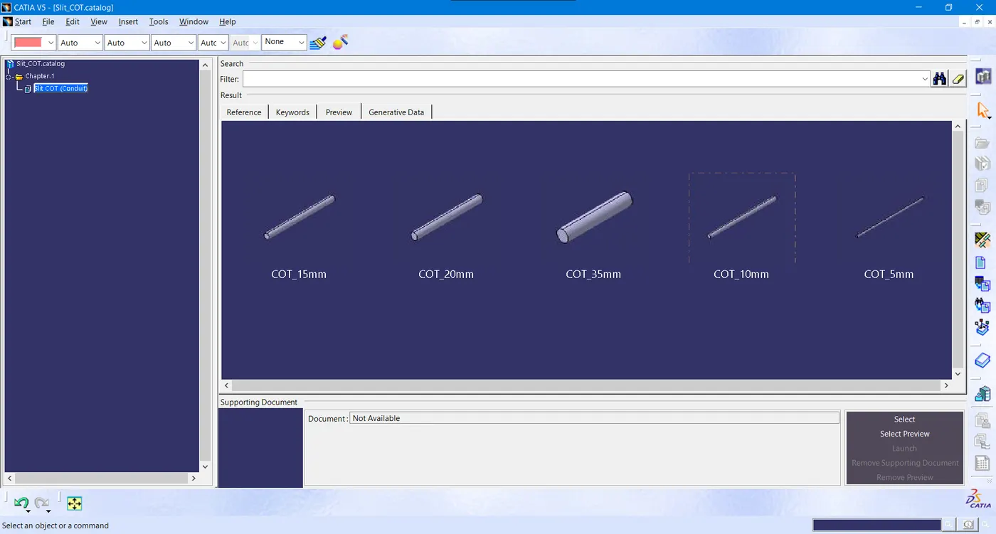
Q3. Create Following Corrugated tubes & add them in Catalogue under “Slit COT” family.
|
Name |
ID (mm) |
OD (mm) |
Thickness (mm) |
|
15mm COT |
12 |
15 |
1.5 |
|
20mm COT |
17 |
20 |
1.5 |
|
35mm COT |
32 |
35 |
1.5 |
|
10mm COT |
7 |
10 |
1.5 |
|
5mm COT |
3 |
5 |
1 |
Q1. P CLAMP:
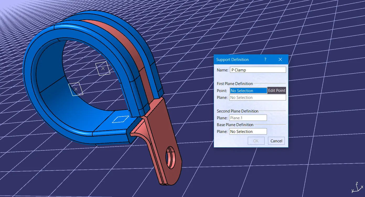
P-Clamp is an Electrical Support equipment which provides support to the wire bundle to remain fixed to the automobile or any components or parts.
The wire bundle can enter and exit from any side as it is a bi-directional equipment. So, we need to specify the Entry and Exit points from both the sides.
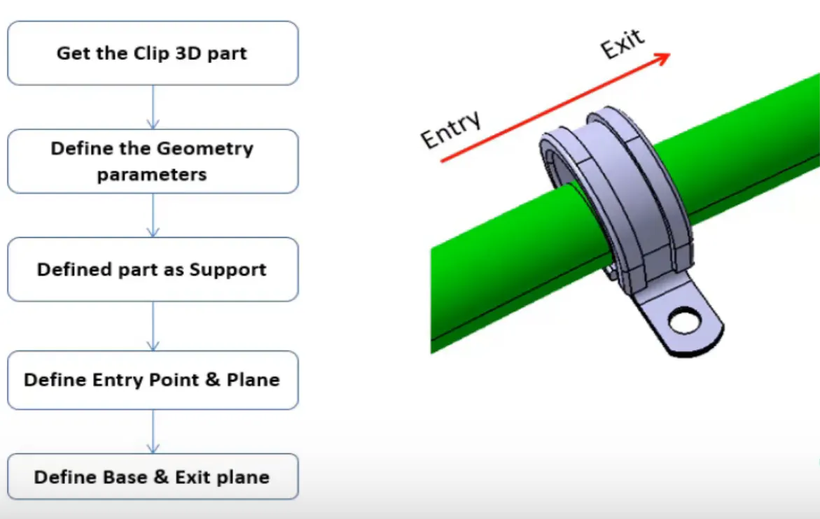
To define the P-Clamp as Electrical Support equipment we need to follow the below steps:
Step - 1:
· First download the CAD part and open it using the CATIA V5 software.
· If required improve and join the surface.
· Now we have to define the geometry parameters. In order to define the geometry parameters, we need to navigate to the Part Workbench.
· Then we need to create points for Entry and Exit points.
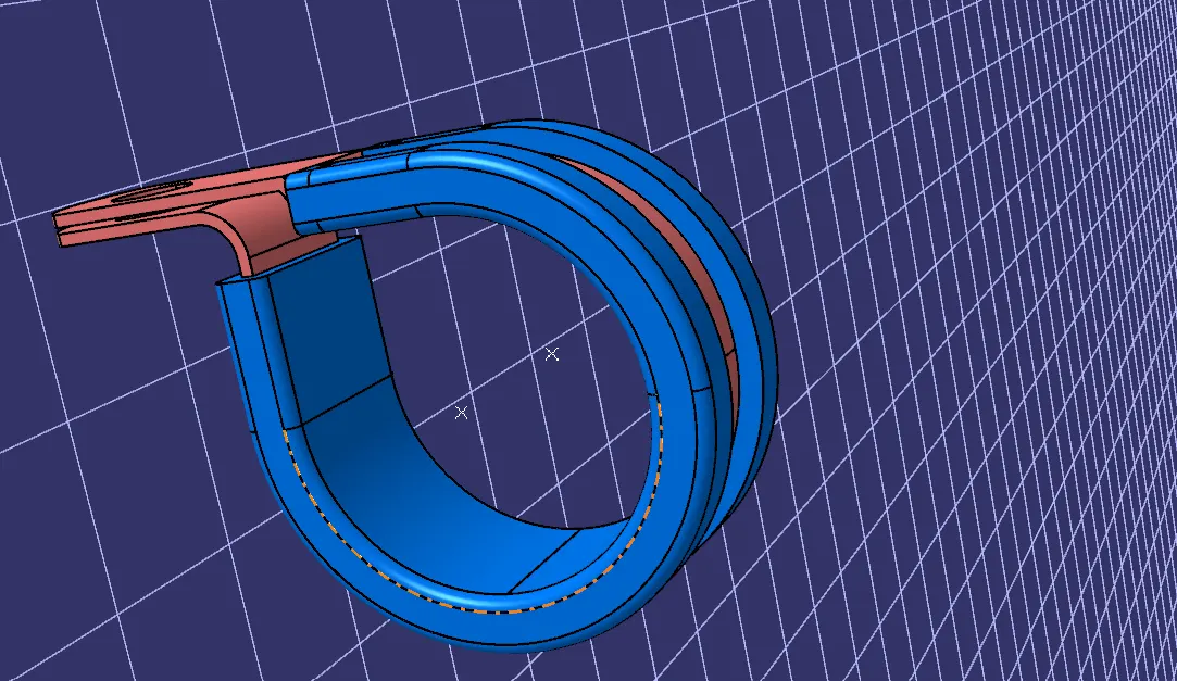
· After creation of point then create Entry, Exit and Base planes accordingly.
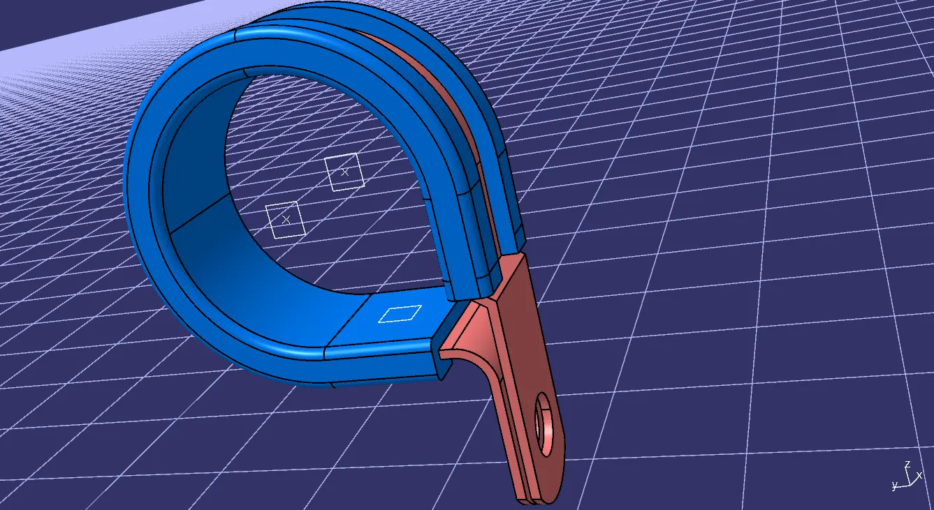
Step - 2:
· Now, in order to define the P-Clamp as an electrical support, we have to navigate to the Electrical Part Design Workbench.
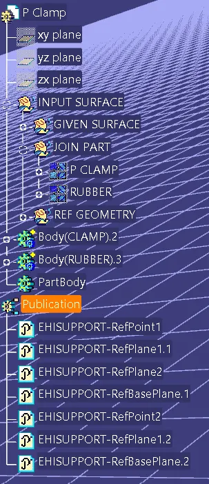
· Now using the 'Define support part' option, we can define the P-Clamp Entry and Exit points.
· As the P-Clamp is bi-directional, we need to define the support from another side also.
Q2. Download following Back shell cad data & define it as Electrical back shell using Electrical Part design Workbench. Define all the necessary properties.
Tyco 1738312-1 https://www.te.com/usa-en/product-1738312-1.html
BACKSHELL:
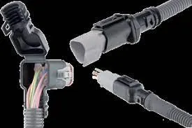
A Back shell is an accessory that mounts to the rear threads of a connector to enhance its operational characteristics. The primary function of a back shell is to provide strain relief, which minimizes stress from the cable, on the junction where the wires terminate to the contacts.
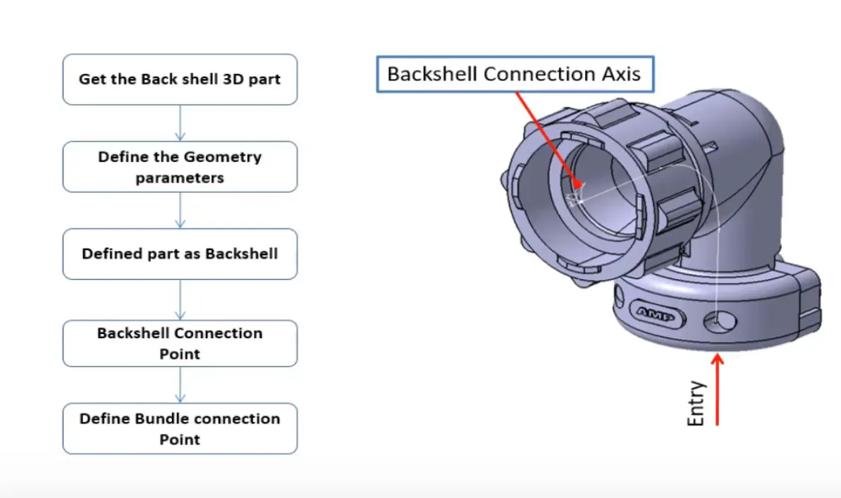
To define the Electrical properties of the back shell we need to follow the below steps:
Step - 1:
- First download the 3-D CAD part of the Back shell and open it using the CATIA V5 software.
- Identify from which side the bundle will enter and the side which will mate with the connector.
- Create point on the bundle entry side.
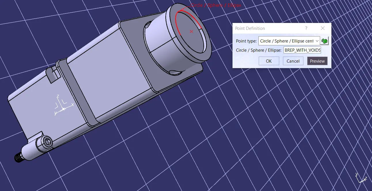
- Create point on the connector mating side.
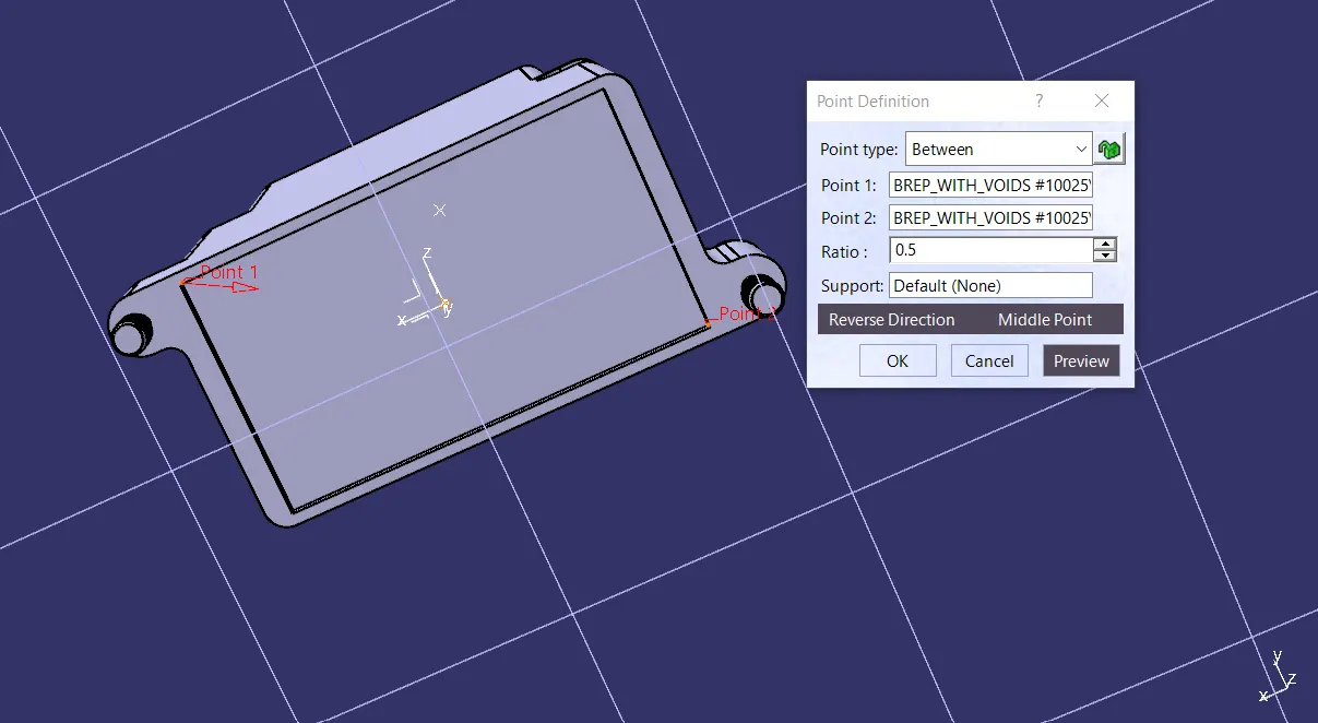
- Create an Axis system at the Connector mating side point which we created earlier.
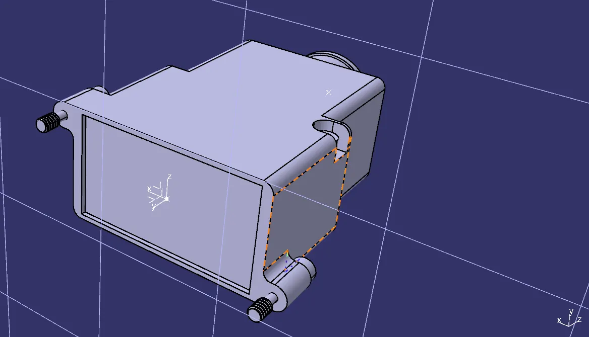
- The axis must be defined as defined for the connectors show that it will connect easily.
Step - 2:
- To define the Electrical properties, we need to navigate to the Electrical Part design workbench.
- There we need to define the component as the 'Back shell'.
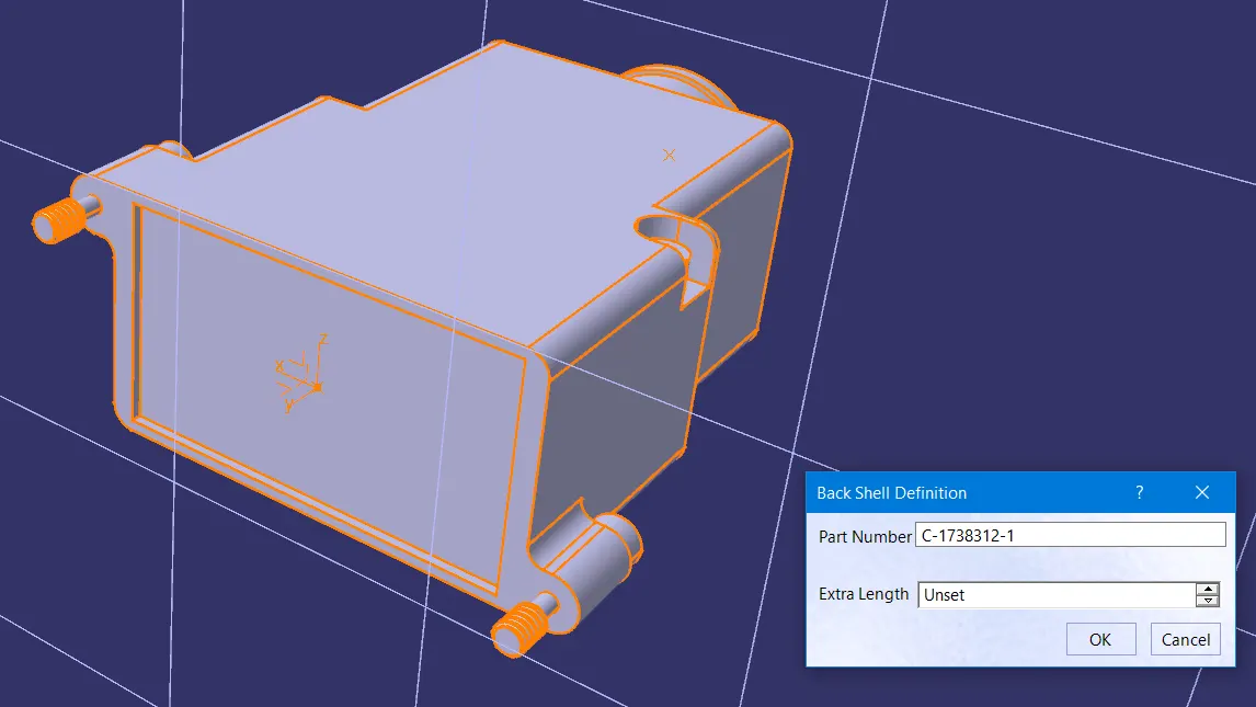
- Define the Back shell connection point.
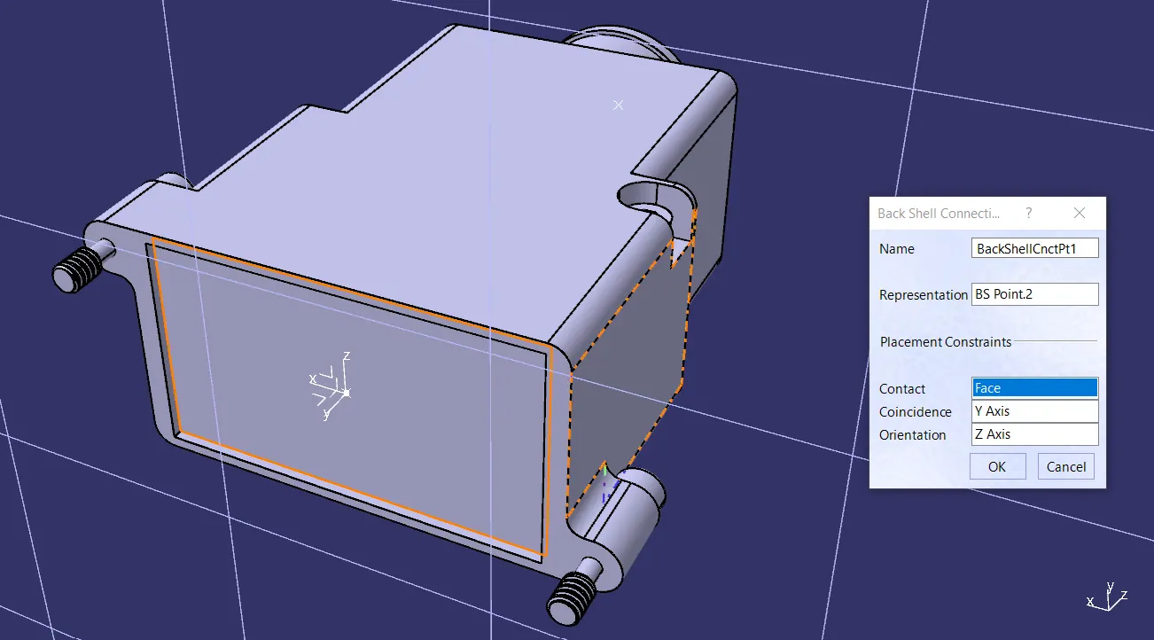
- Then define the Bundle connection point.
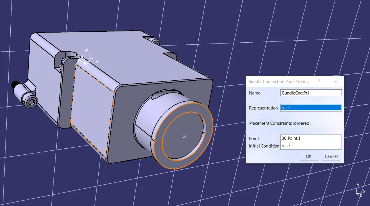
Q3. Create Following Corrugated tubes & Add them in Catalogue under “Slit COT” family:
CORRUGATED TUBES:
Corrugated tubes are tubular structures with a corrugated (ridged or grooved) surface. These tubes are designed to provide flexibility, protection, and routing for electrical wires, cables, and other similar applications.
The corrugated design imparts flexibility and allows the tube to bend and flex without compromising its protective properties.
It is essential that we design proper corrugated tubes for both safety and durability for our wiring harness.
Step 1:
· Now we have to define the catalogue family and its type, for that we need select “add family” and proceed with the naming and type as “conduit”, then proceed to save the catalogue file in suitable folder.
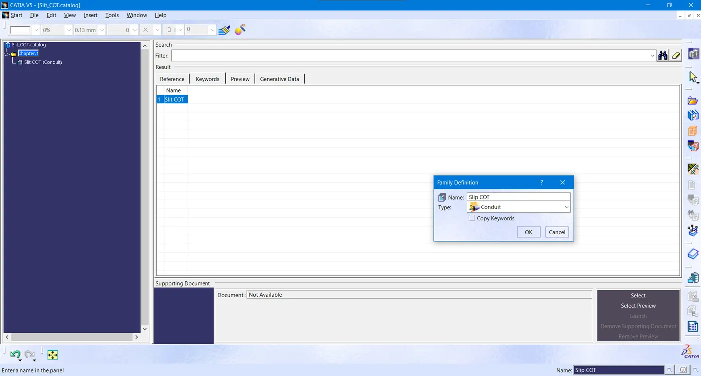
· For creating the corrugated tubes, first we have to enter the Electrical Part Workbench of the CATIA.
· Then we need to select the Protection Covering under Electrical Device Definition, on which we can edit our parameters of the corrugated tubes.
· For example, the inner diameter of the COT_5 is 3mm and thickness is 1 mm as per our project requirement. So similar data is entered in the Protection Covering definition.
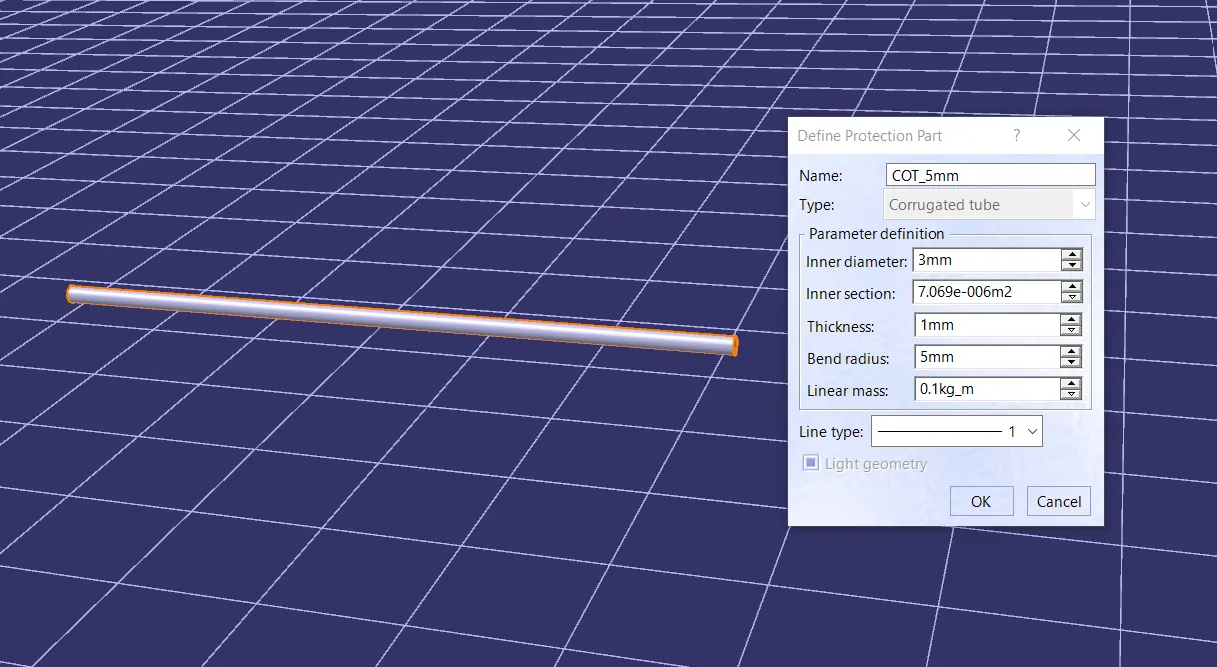
· Similar steps are followed for each and every COT_XX as per our data.
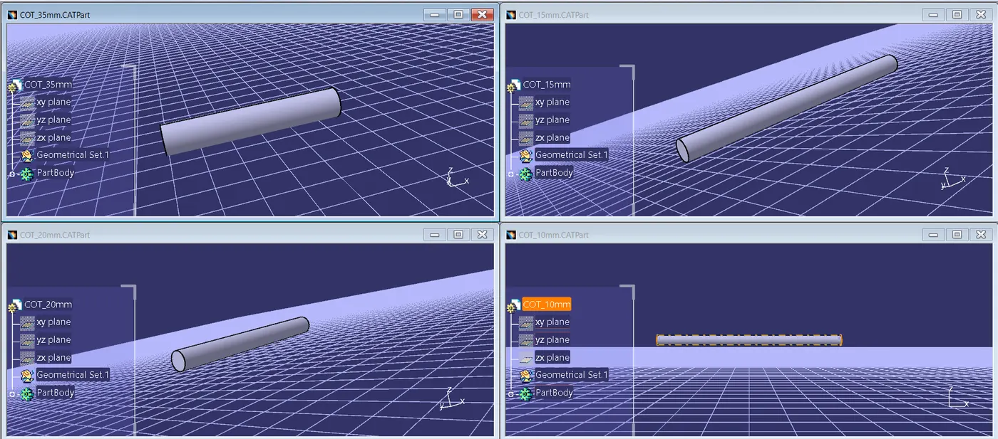
· Then store this cot tubes under the catalogue file for easier access.
· For that use “store device” option in the Electrical Part Workbench.