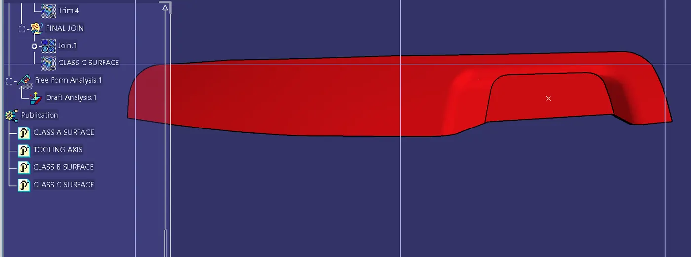
Week 9 - Challenge 2 - Switch Bezel Design
Introduction:
Draft Analysis is the process of analysing the designed plastic part if it has the drafting angles as per the requirement. In CATIA, draft analysis is done by the tool called Feature Draft Analysis. It shows the different draft angles available at different parts and says if it meets the requirement or not by various colour codes. In this example, a Switch Bezel’s class-A surface is taken for the draft analysis study.
Objective:
To do analysis the switch bezel in CATIA by using draft analysis.
Steps involved to complete draft analysis:
1. Creating the tooling axis:
The given part is first checked for its boundary to find if there are any gaps or openings or discontinuity in the boundary. If there is any boundary you need to close the boundary before go to further.
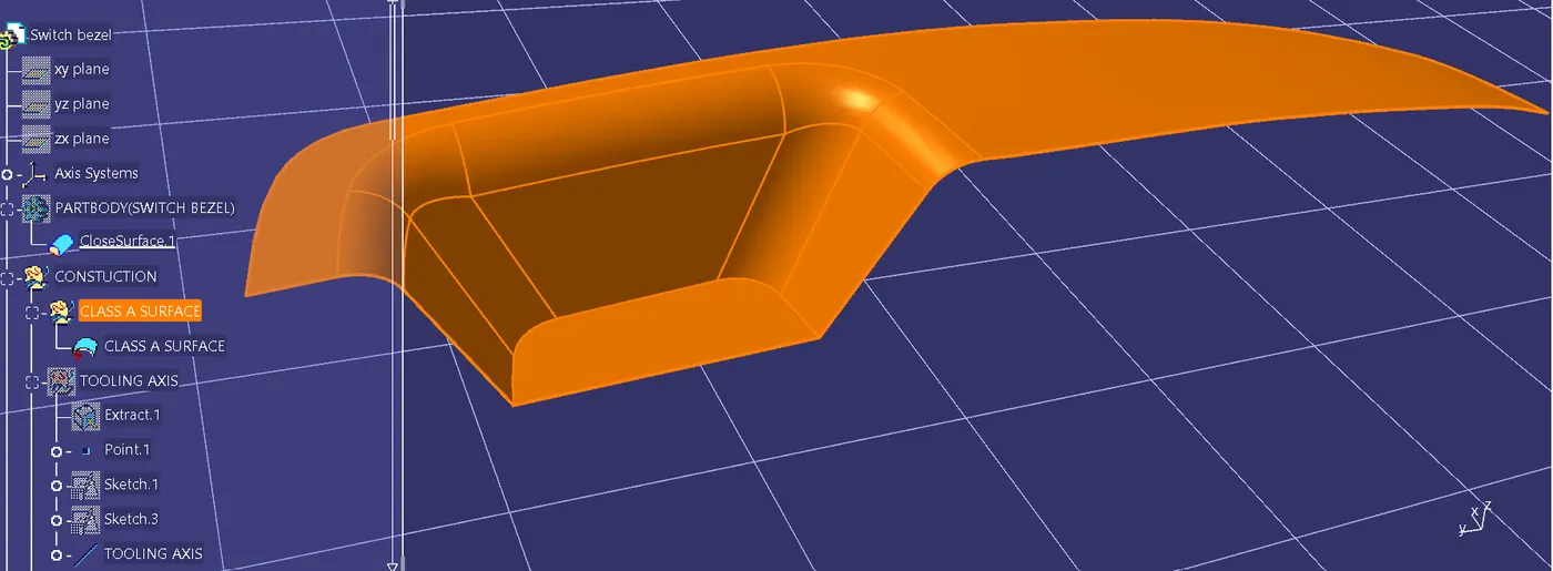
After completing the boundary check insert a point at almost the symmetric centre of the part and insert a coordinate system at the point. The coordinate system should be facing in all directions the same as the default coordinate system.
Before actually creating the tooling axis, we need to create two dummy tooling axis on the class A surface at a point we created earlier. Then by using bisecting line command we need to find the final tooling axis.
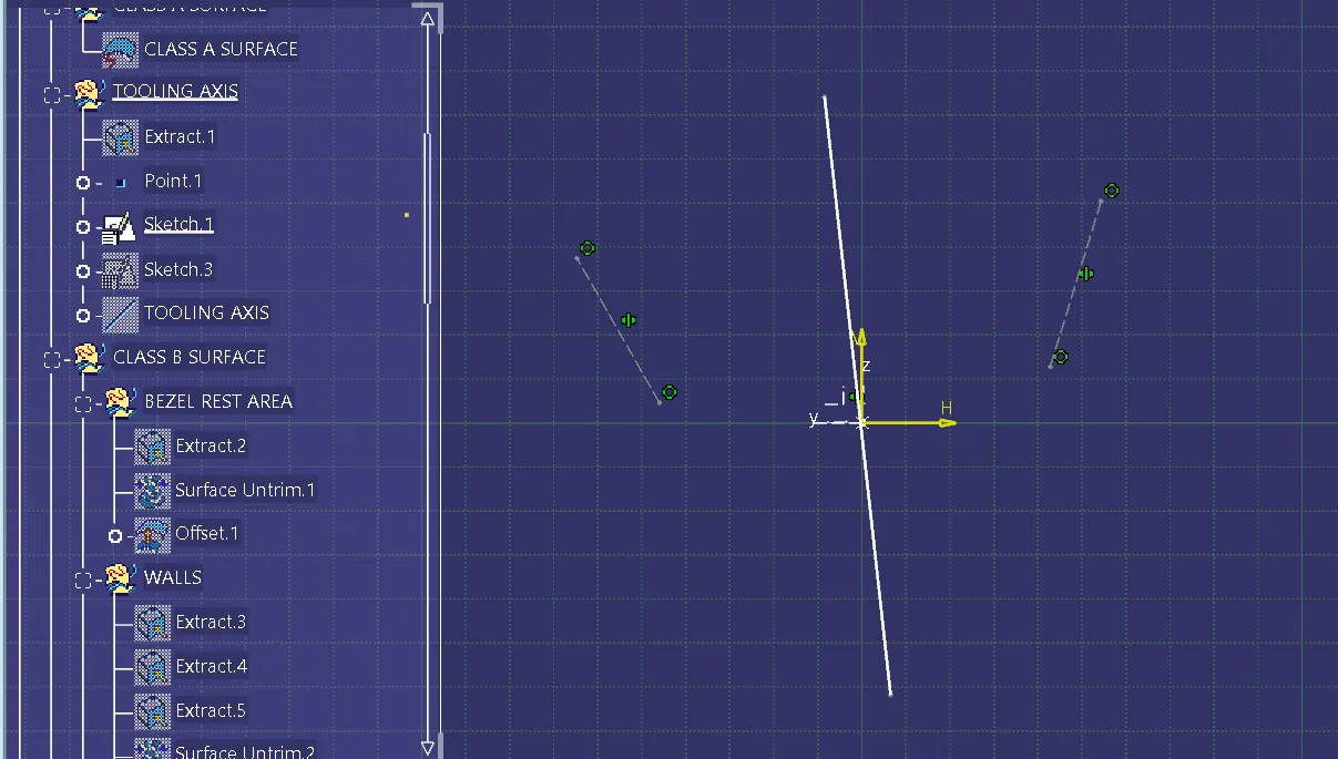
First do creating dummy axis on the ZY plane, by taken reference from the class a surface. With that reference lines by using bisecting line command, we can create dummy tooling axis for the ZY plane. The below images show the dummy tooling axis for ZY plane.
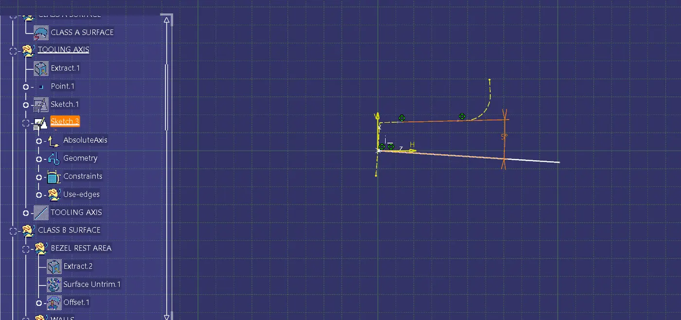
Then create dummy tooling axis for XZ plane, by taken reference from the class a surface. since there is only one intersection line, a dummy tooling axis is drawn at 5 degrees form the reference line. The below images show the dummy tooling axis for XZ plane.
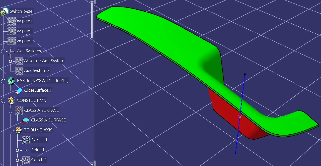
Now, using the two dummy tooling axes, use the bisecting line to create a new line (TOOLING AXIS) and select the result in the required direction. This will give the tooling axis we require. It can be made bold and the colour can be changed for better visibility.
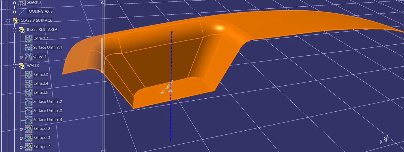
2. perform draft analysis
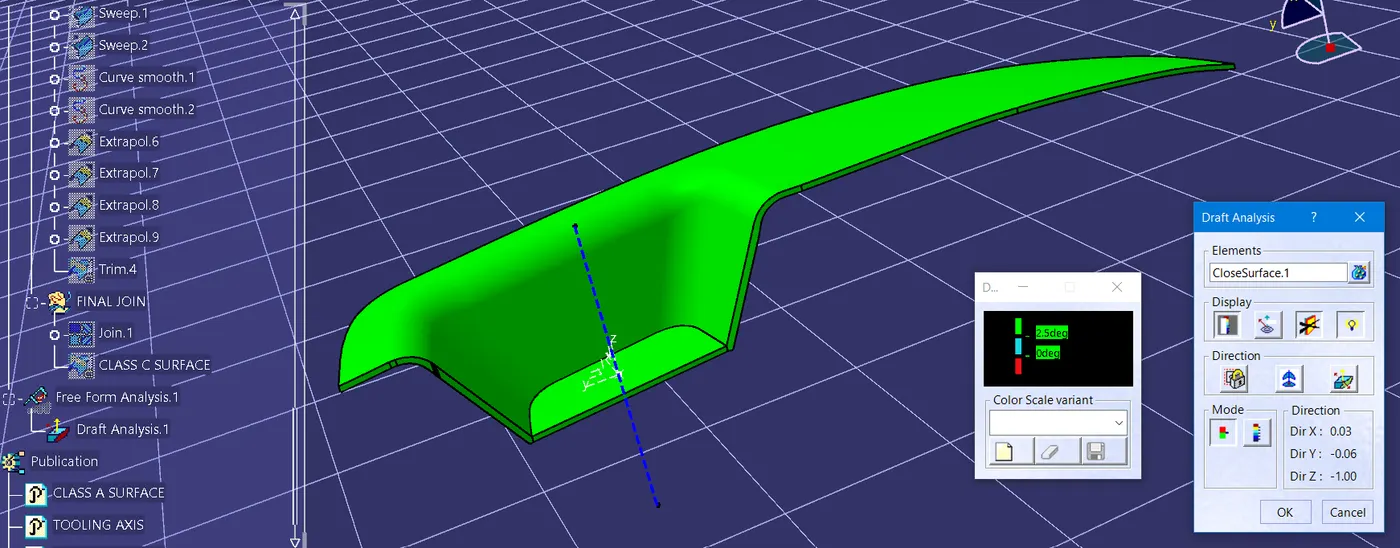
Now, perform the draft analysis of the Switch Bezel. To do so, go to tools > analysis > Feature Draft Analysis. This tool has three groups of options namely; mode, display, and direction. First, the second icon from the direction group is selected and the red dot in the compass is clicked and dragged to the part to be drafted. The line in the dragged element is matched with the tooling axis and it is locked using the first icon in the direction group. It will define the tooling axis direction and lock it. Then click the Switch Bezel. It will create different colours on the main part. If the part is in green colour, it shows the draft angle is ok, if it is not in the sense then do correct the sketch of the tooling axis to correct it. The final result shows that all areas in the switch bezel maintain an thickness of 2.5mm.
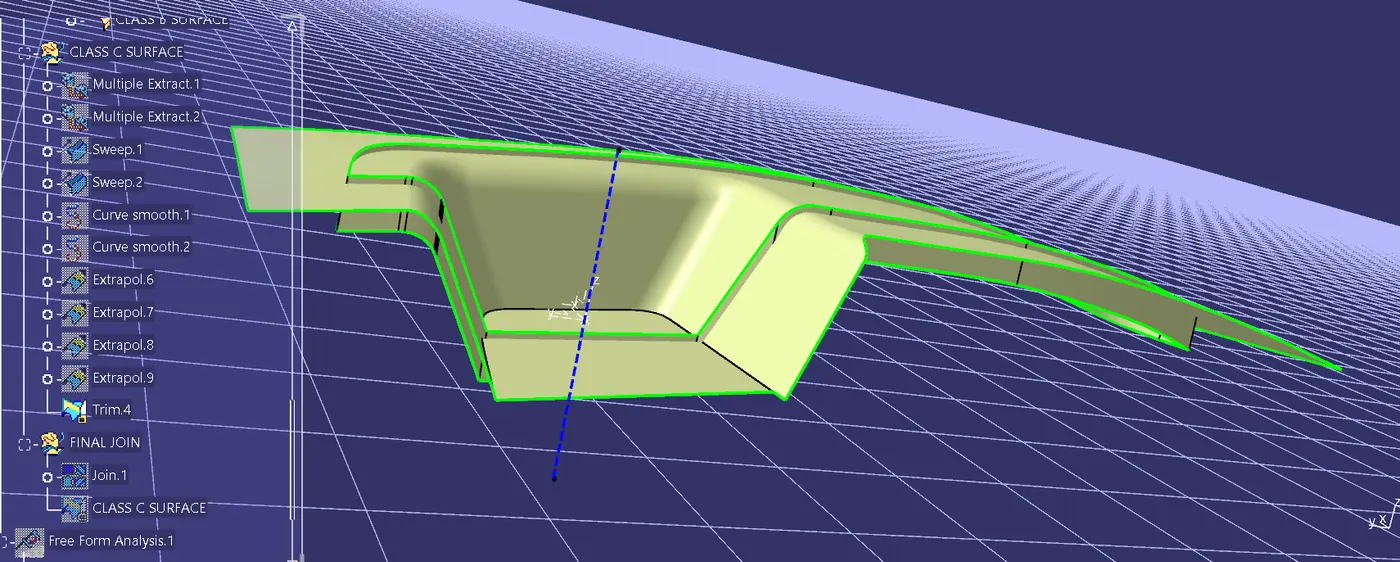
The below image shows the before and after state of final trimming
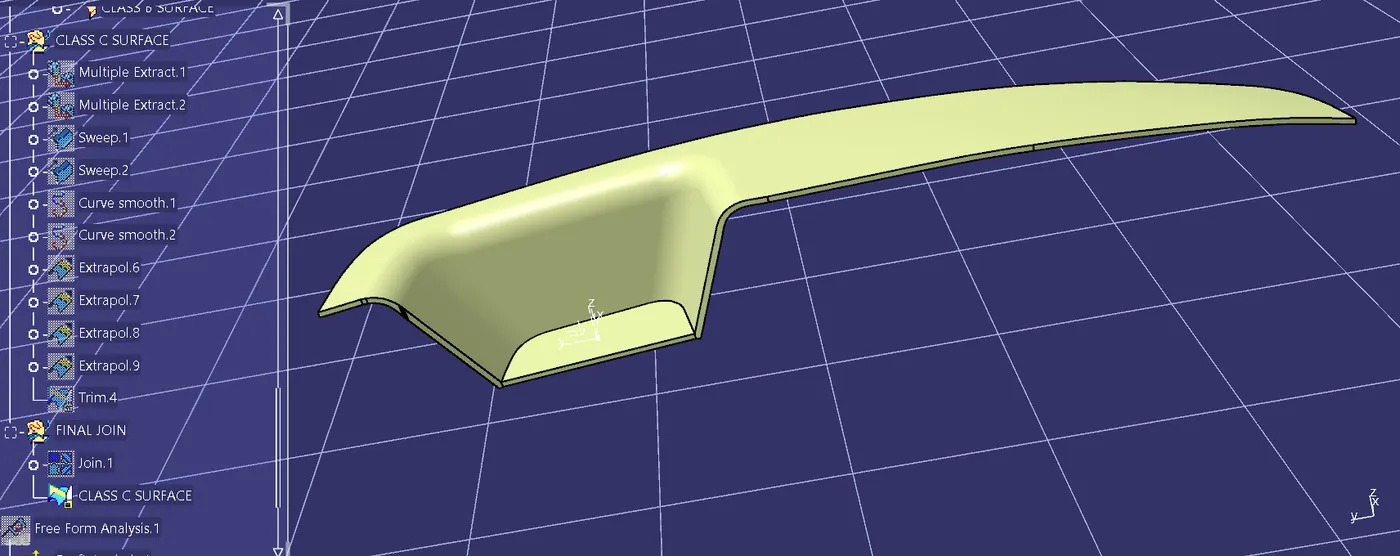
The below image shows the solid surface creation using close surface command
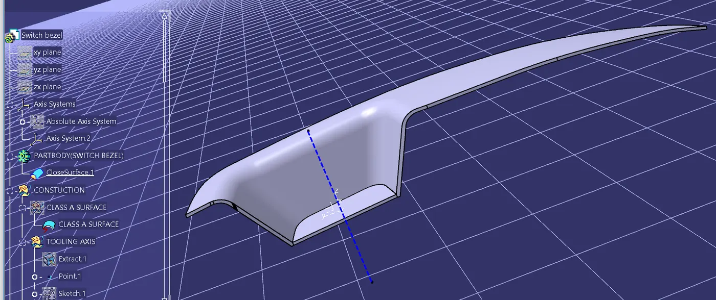
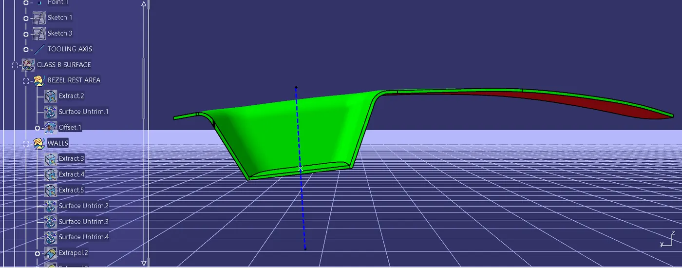
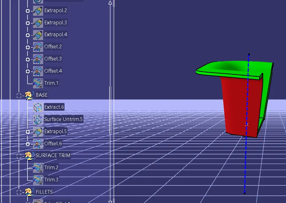
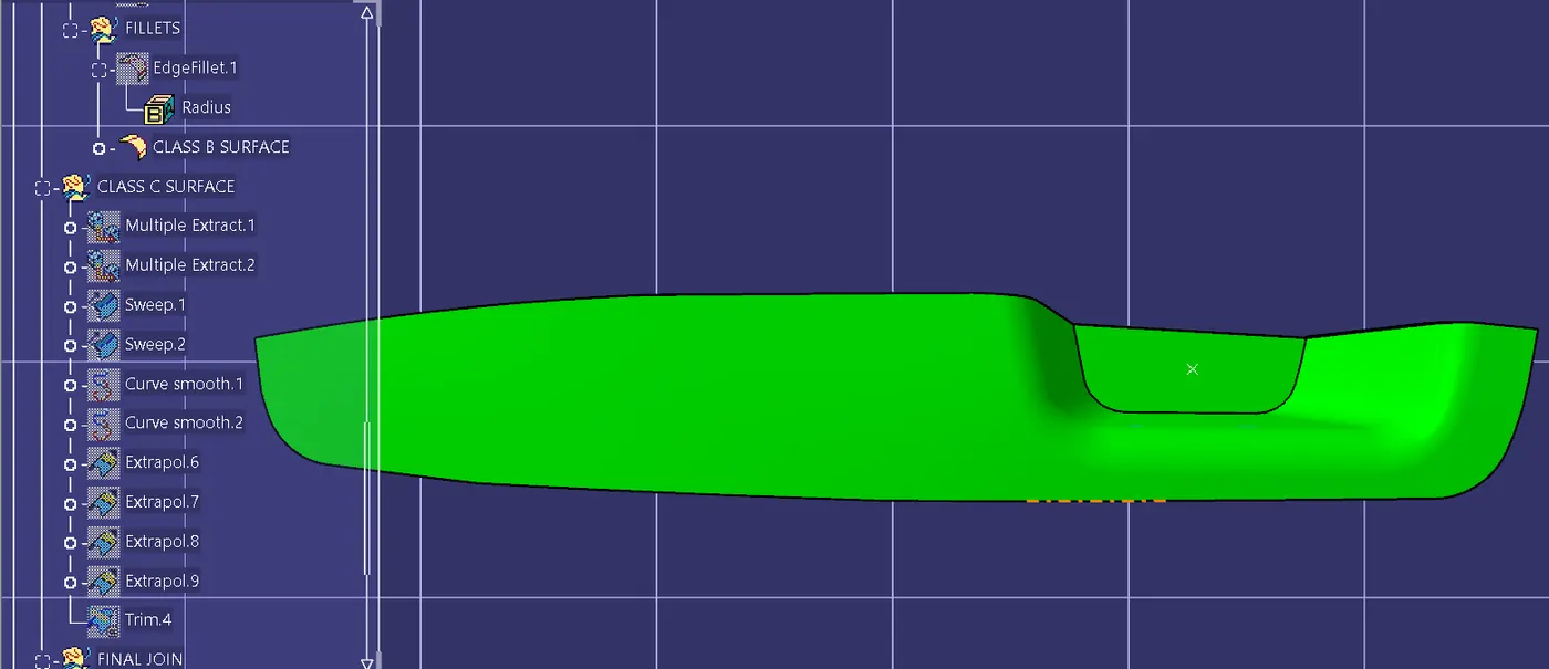
Screenshots of various views with tree structure: