Wiring harness routing & packaging Rules Week 3 Challenge
Objective: To define Support Part, Back Shell, & Protective Coverings as electrical parts in CATIA V5.
Theory:
Clip Definition:
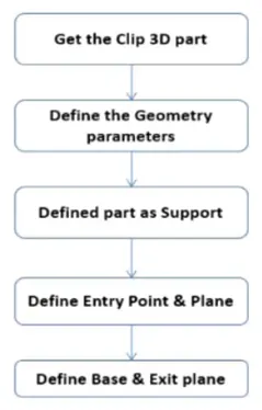
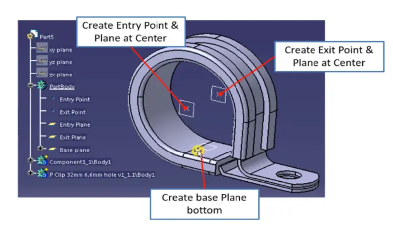
- Import the CAD file into CATIA V5.
- Create two points which will be used as entry and exit points.
- Create entry and exit planes at these points parallel to the opening surface.
- Create a base plane on which the wire routing will rest.
- Define the part as the support using one entry point, entry plane, exit plane, and base plane.
- Repeat the same using another point. Note that the exit plane will already be selected due to the step above.
- We do this twice because designers can use this clip in either direction.
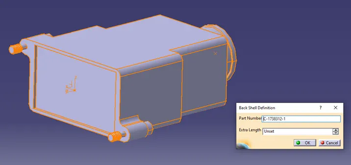
Backshell Definition:
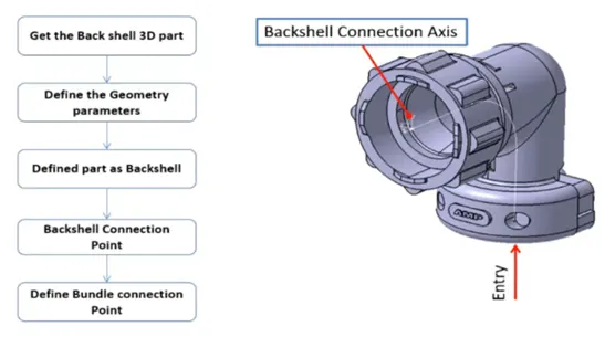
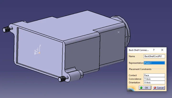
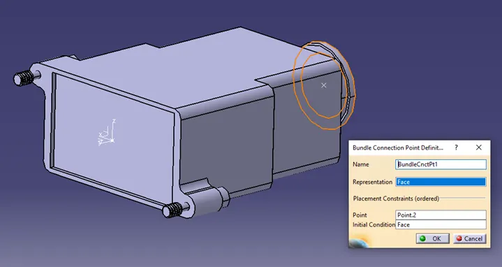
- Create two points, one backshell entry point and second the bundle connection point.
- Create an axis system at the backshell entry point.
- Define the part as the backshell in Electrical Part Design.
- Define the backshell connection point and bundle connection point.
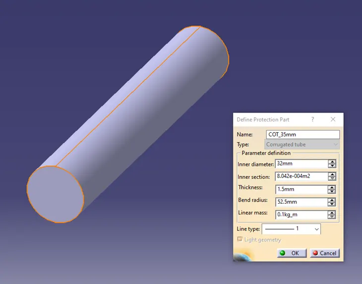
Protective Covering Definition:
- Go to Electrical Part Design workbench.
- Select Define Protection part and click on the part body.
- Enter the parameters and bend radius (1.5 x OD).
Catalogue Creation:

- Click on New Part >> Catalogue Document >> Add Family >> Name >> Type (Conduit for COT tubes) >> Save.
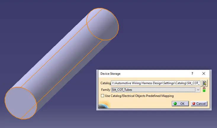
- To store the tubes into the catalogue, click on Store Device Command>>Select Catalogue>>Select Family>> OK
Results:
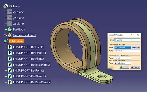
Clip:
Backshell:
COT_Tubes:
Conclusion:
Hence, we have successfully defined clips, backshell and protective coverings as electrical parts in CATIA V5.