Wiring harness routing & packaging Rules Week 3 Challenge
Q1. Download following clip cad data & define it as Electrical support using Electrical Part design Workbench. Define all the necessary properties.
Hellarmann Tyton – 21160129
Answer:
According to provided cad data, P-Clamp (Hellarmann Tyton – 21160129) is designed and defined as electrical support by using Electrical Part Design Workbench. Now, the properties of P-Clamp are defined as below--
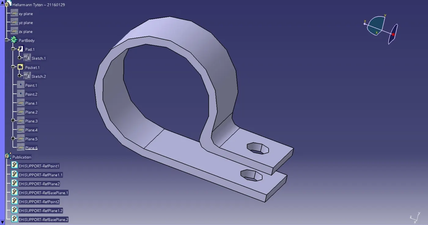
- The final electrically defined P-Clamp is shown in above image.
- First, we have to define geometrical parameters in part design i.e. points & planes.
- Then, defined the P-Clamp electrically as a support in electrical part design workbench.
- While defining a P-Clamp as support, also need to define necessary properties like- 1)Entry point & plane 2)Base plane 3)Exit plane.
- P-Clamp is bi-directional, means it can be go either from left to right or right to left.
- We need to define properties two times to give flexibility to the designer to select the clamps to use in both bundle direction.
- This is the important part of the wire harness, used for the firm fixing of the wiring harness.
Q2. Download following Back shell cad data & define it as Electrical back shell using Electrical Part design Workbench. Define all the necessary properties.
Tyco 1738312-1 https://www.te.com/usa-en/product-1738312-1.html
Answer:
PROPERTIES OF BACK SHELL
After downloading Back shell cad data and defining it as electrical back shell using electrical part design workbench, now we have to define properties for the same as follows--
1. Back shell Connection Point:
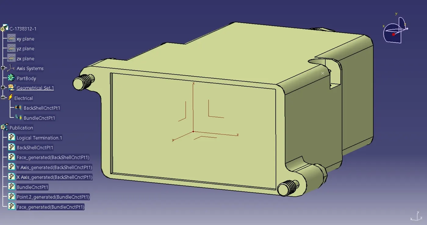
- In above image, back shell connection point is shown.
- This back shell connection system always connects with the wire entry side or back side of the connector, so this is known as Back Shell Connection Point.
- The procedure for selection of point, axis system and orientation is same as the connector connection system.
- Ensure that a point and axis orientation at back shell connection system should be identical with the mating part of the connector back end.
- Back shells are plastic molded parts used for either for protection or to improve appearance of wiring harness.
- Back shells are not compulsary parts of wiring harness, these parts are always optional and driven by cost.
2. Bundle Connection Point:
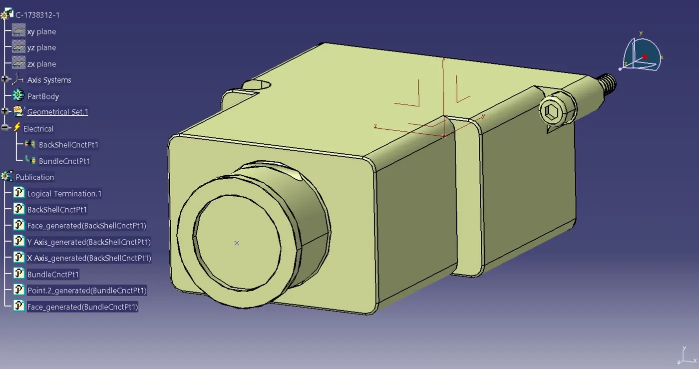
- In above image, bundle connection point is shown.
- Now, here the end side or back side of the back shell will define as wire entry side.
- This point is located at the center of wire entry side or bundle segment side, known as Bundle Connection Point.
- Bundle connection point at the connector wire entry end will define as back shell connection point.
Q3. Create Following Corrugated tubes & Add them in Catalogue under “Slit COT” family.
|
Name |
ID (mm) |
OD (mm) |
Thickness (mm) |
|
15mm COT |
12 |
15 |
1.5 |
|
20mm COT |
17 |
20 |
1.5 |
|
35mm COT |
32 |
35 |
1.5 |
|
10mm COT |
7 |
10 |
1.5 |
|
5mm COT |
3 |
5 |
1 |
Answer:
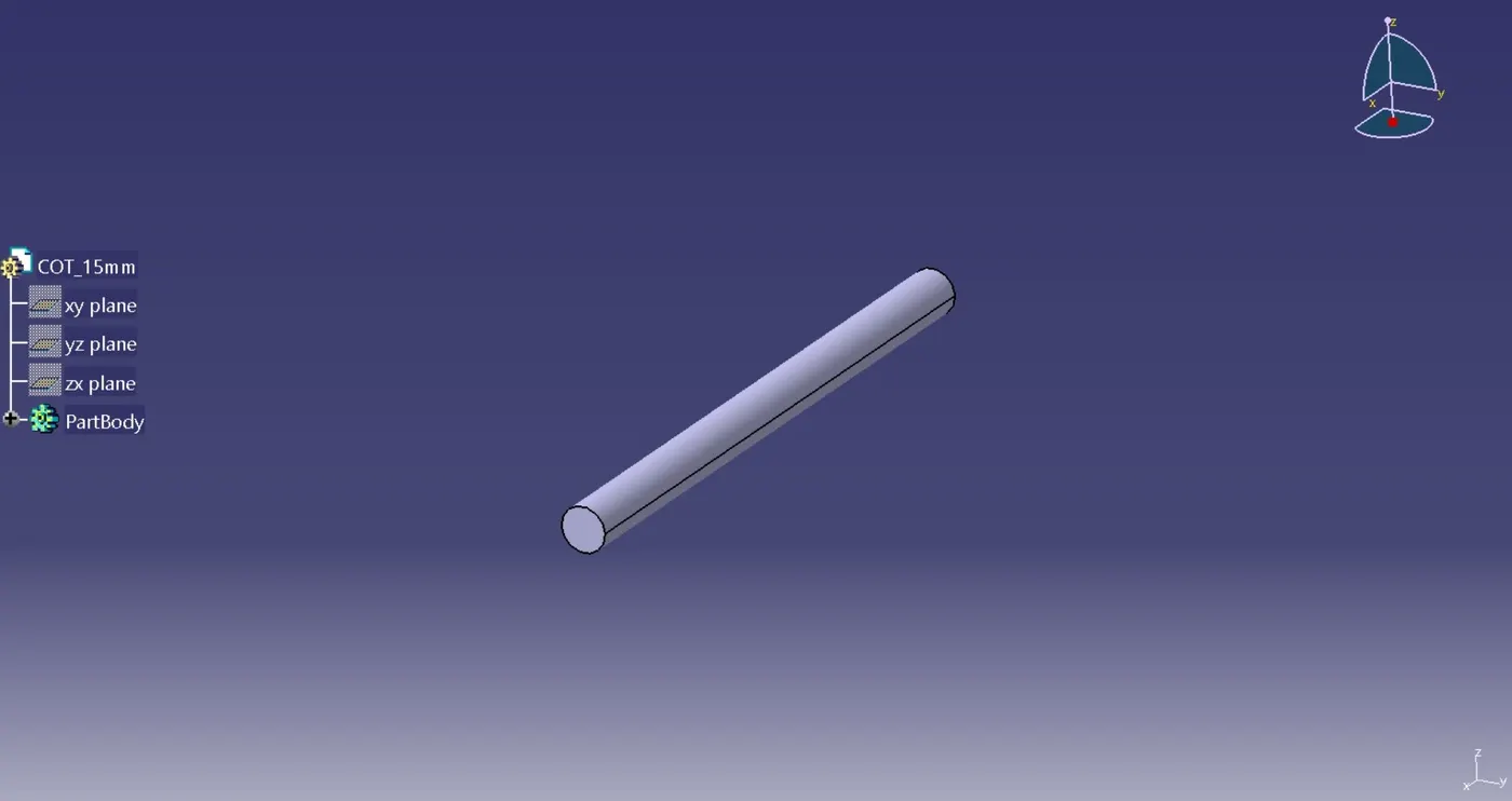
15mm_COT
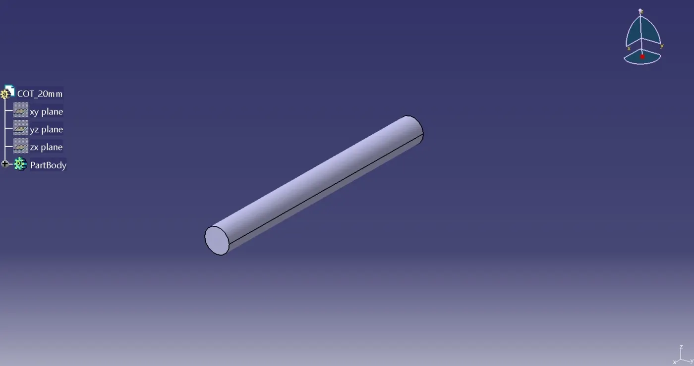
20mm_COT
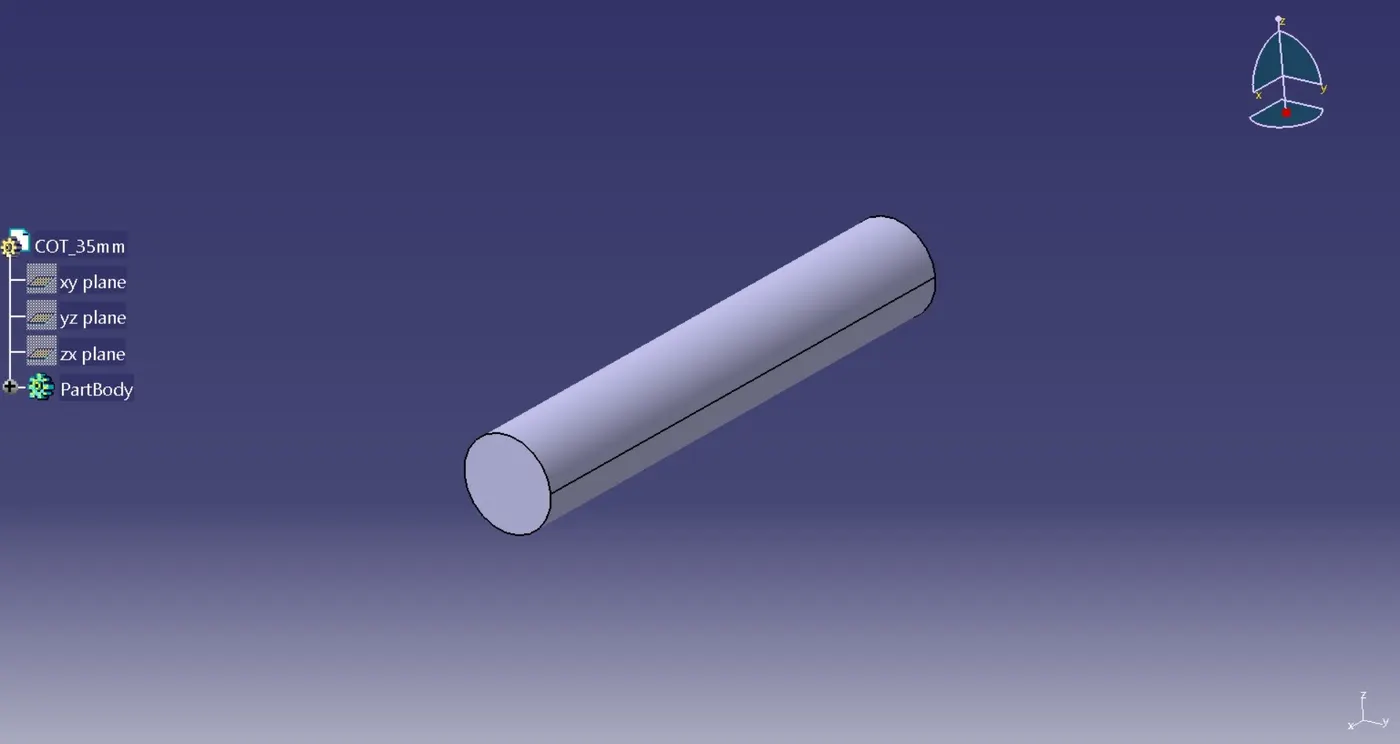
35mm_COT
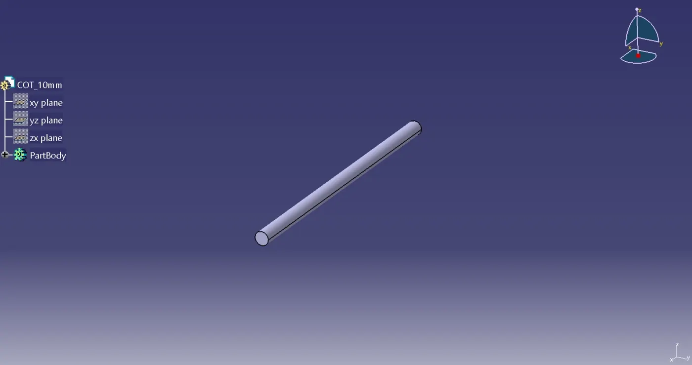
10mm_COT
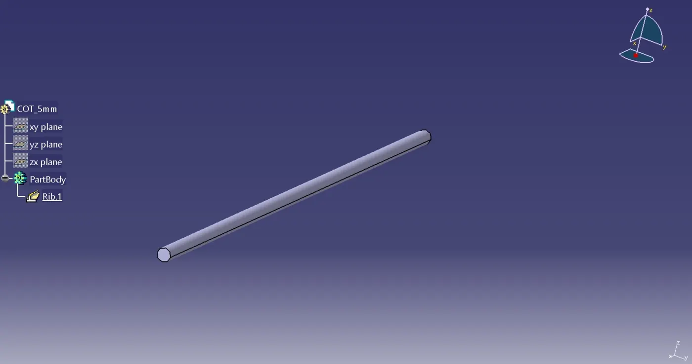
5mm_COT
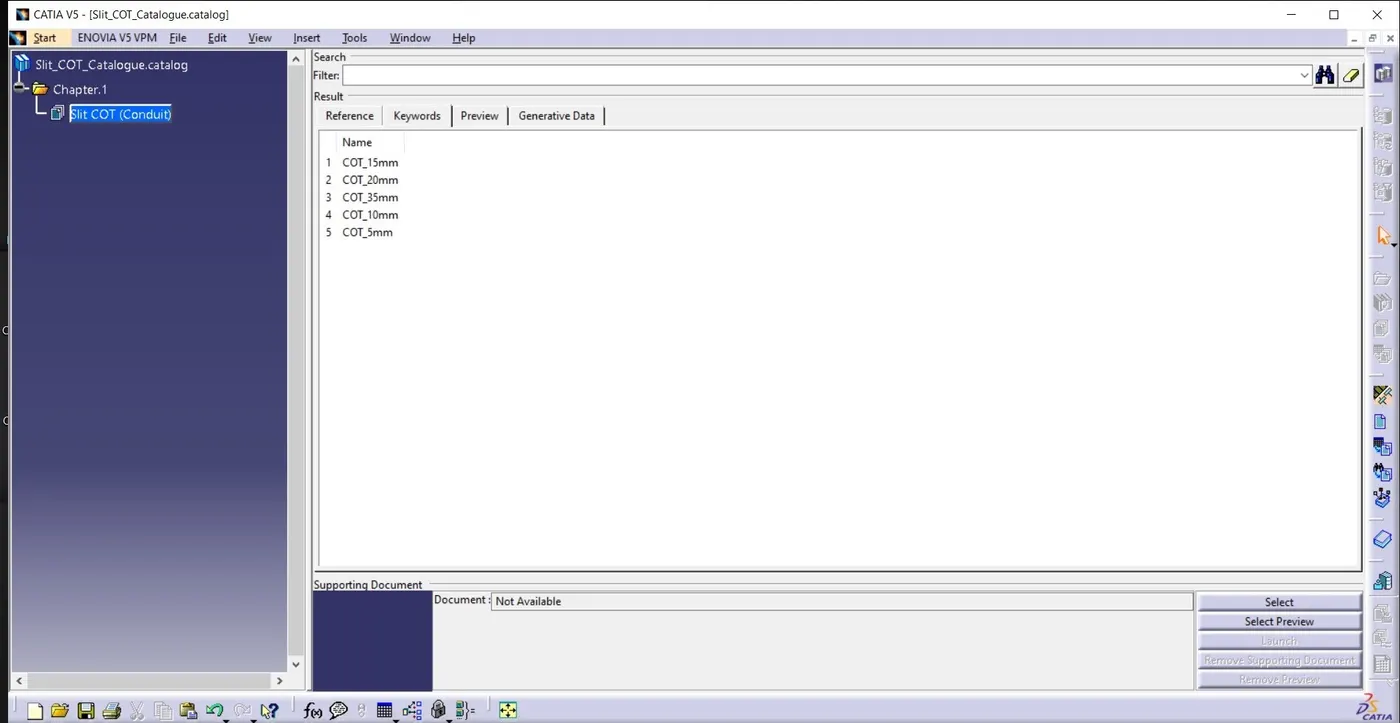
Slit_COT Family_Catalogue