Wiring harness routing & packaging Rules Week 3 Challenge
Ans 1
Objective
While downloading the cad file using the link given below and defining the clip as electrical support using the Electrical part design workbench and defining all the necessary properties required.
P Clamp
It is a device that keeps the wiring harness or bundle in place and keeps ensure the placing of the bundle in the right place by fastening it to a point by using the bolt.
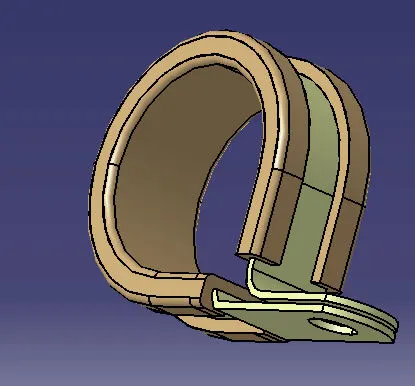
While it has the two parts the maetalic part which is the main body and rubber cover which protects the wiring harness from the damges due to the metalic body.
Parameters which are required in the P Clamps
- Entry point
- Entry plane
- Exit plane
- Base plane
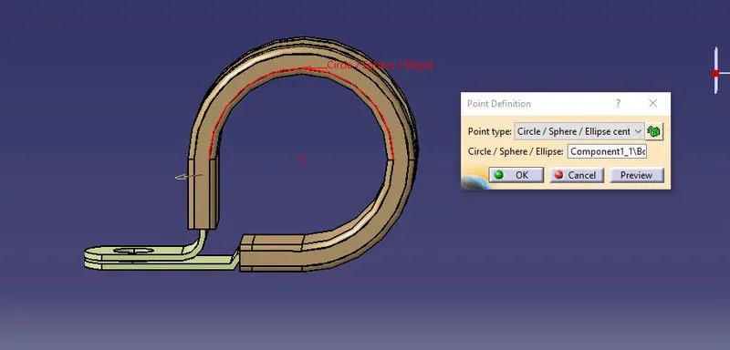
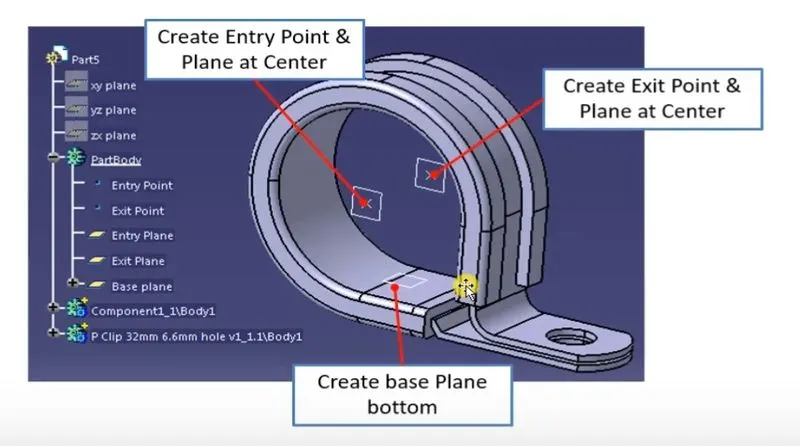
We can create the Entry point at the centre of P clamp using the point tool providing the defination as ciricle/sphere.
For the cretion of entery plane we are using the plane tool and plane type as parallel through point while taking the P calmp outer surface as a refrence element which is normal to the bundle or the harness.
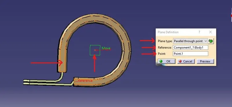
as we know that P clamps are bi-directional in nature so we are required to follow the same procedure for the opposite of the clamp also.
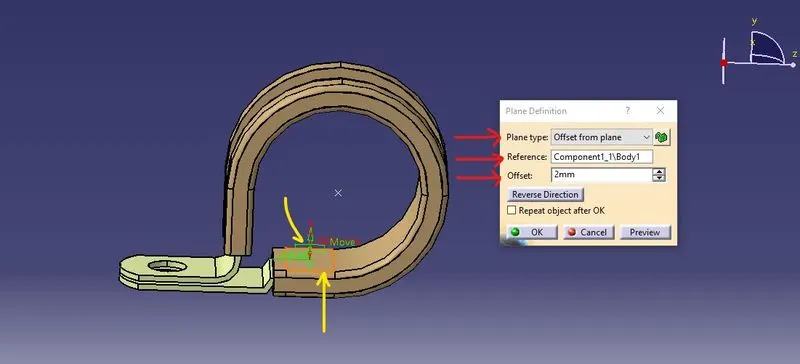
For the formation of the base plane we are using the plane tool and plane type as parllel throught point and taking the base plane of P clamp as a refrence plane and offset it to a distance of 2mm.
For converting the mechanical part P clamp into the electrical support, we are using the electrical part design workbench for the conversion.
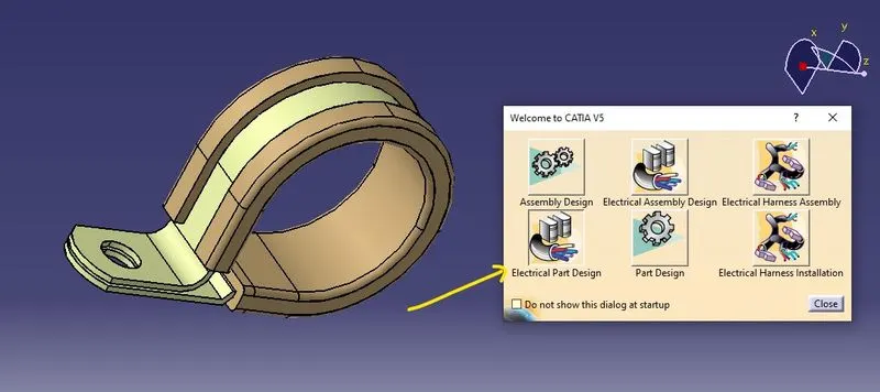
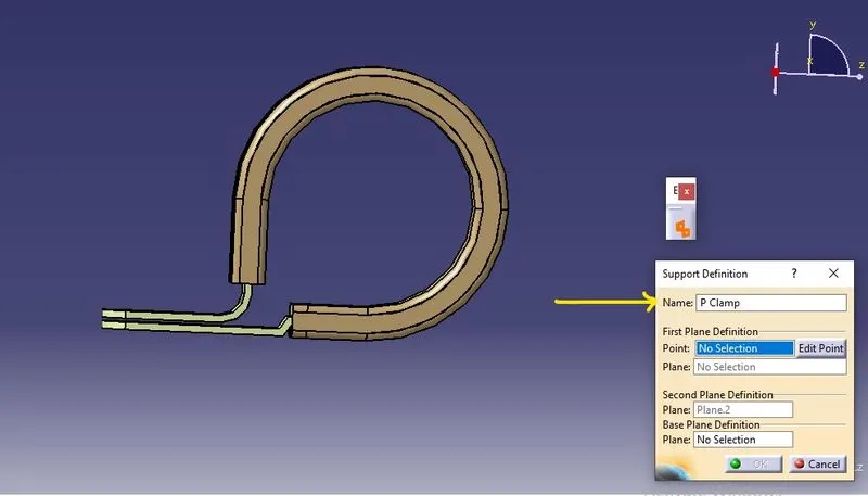
Before defining the geometrical parameters for the entry, exit, and base, we needed to define the part as an electrical support using the define support part tool.
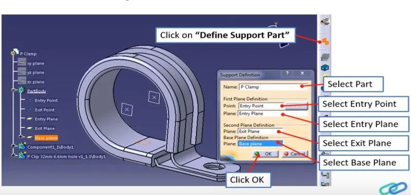
The image above shows how to define the entry,exit, and base planes, respectively.
We are required to do the same steps one more time, as P calmp are bi-directional in nature. While repeating the same steps for the opposite side, we only need to select the entry point, plane, and base plane, as the exit plane will be automatically selected by the catia.
Ans 2
Objective
While downloading the cad file using the link given below and defining the clip as electrical back shell using the Electrical part design workbench and defining all the necessary properties required.
Backshell
These are plastic parts used at the wire entry side of connectors for various reasons, such as protection,improving aesthetics, and others. These are always optional, as they come at a cost to consider.
Tyco 1738312-1
https://www.te.com/usa-en/product-1738312-1.html
By using the above link we download the required part for our work
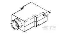
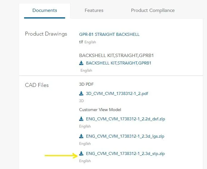
using the documents tab to download the cad file.
we can also see the properties of the backshell before using it in our assembly by using the features option.
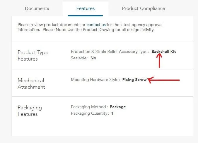
After downloading the required cad file we now move forward with the creation of the various parameters for our backshell. For the creation of various parameters, we require the following point in the part.
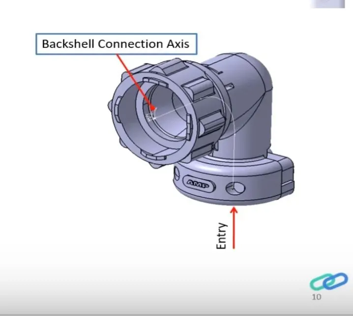
Entry Point
From this point, the bundle harness enters the backshell.
For the creation of the entry point, we create the point at the midpoint of the entry face.
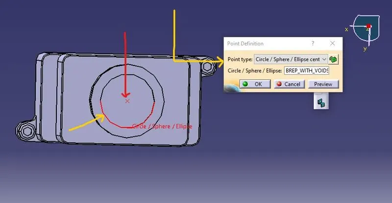
We can create the Entry point at the centre of backshell using the point tool providing the defination as ciricle/sphere.
Backshell Connection point
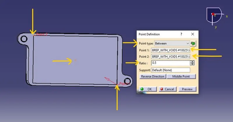
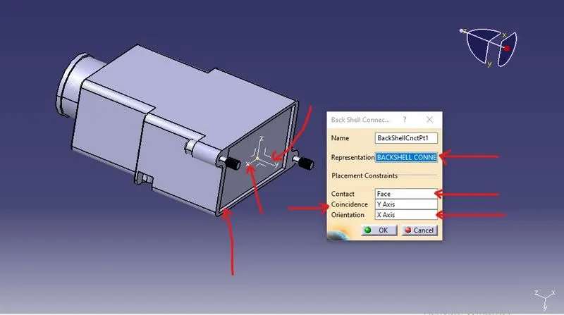
It is the point where the backshell meets the other mating parts, so here we require a point as well as an axis.
using the between type of point definition to create the point at the midpoint on the face select two points and give the ratio as 0.5 to create the required backshell connection point.
Axis
we must create the axis for the proper facilitation or for the proper seating of other parts with the backshell.
choose the Y axis as our co-incidence axis.
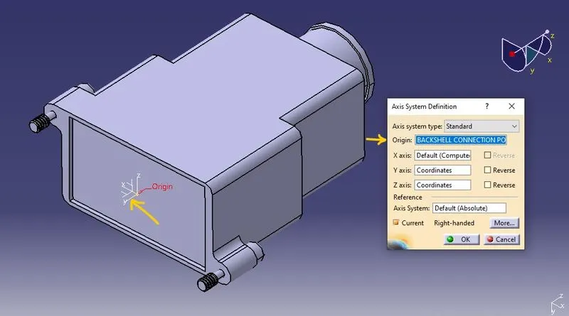
For converting the mechanical part backshell into the electrical part backshell, we are using the electrical part design workbench for the conversion.
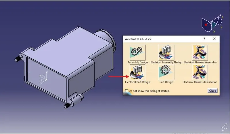
To convert the required part into the electrical component we use the define backshell tool option
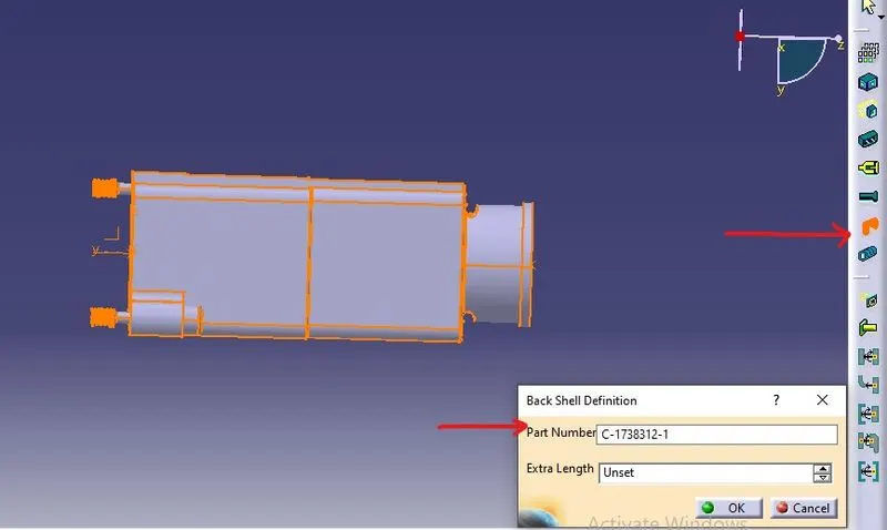
We now need to define the point and axis we created in the part workbench in the electrical definitions, for which we use the backshell connection point to define the backshell connection.
Ans 3
Objective
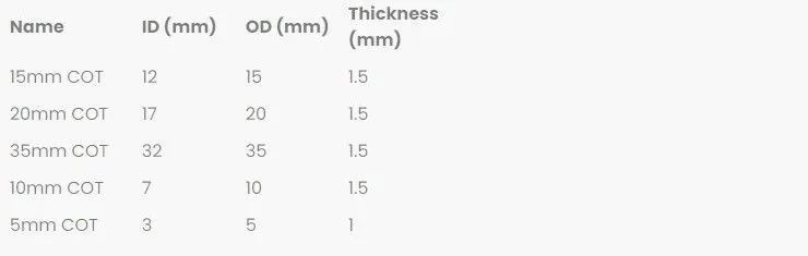
Make the following corrugated tubes and add them to the catalogue under "slit COT"
catalog
It is a document that keeps a list of references of other Catia parts and features which we can use these part whenever required.
Step 1
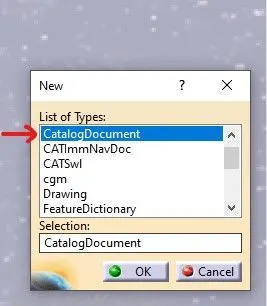
Clicking the New option present in the file tab and using the CatalogDocument in the new option to form the new catalog file for the same.
Step 2
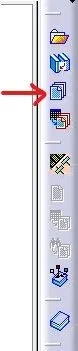
Using the add family option to open the new tab for the creation of a catalog
Step 3
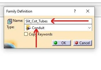
Giving the name of an electrical component for example Slit_Cot_Tube and giving the type in the family definition as Conduit to save our electrical component in this catalog.
Conduit
Electrical conduits are flexible, resilient, corrugated cylindrical protectants that encase your cables to protect them from damage.
For the making of the electrical conduit, we are using the electrical part design workbench.
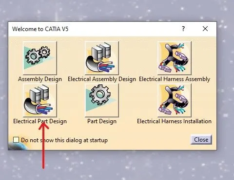
For the formation, we are using the define protection part tool.
In this, the details such as inner diameter, thickness, and bending radius are given, while the bending radius depends heavily upon the flexibility of the conduit; if the material is more flexible, the bending radius would be less, and vice versa; but generally, the imperial relationship suggests choosing the bending radius as 1.5 times the outer radius of corrugated tubes. while choosing the conduit type as corrugated tube and keeping the option of light geometry set to on.
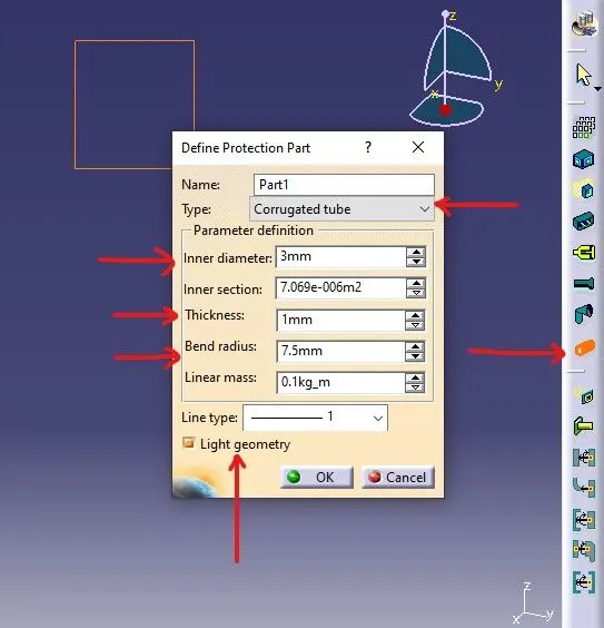
Repeat the same for the rest of the tubes as per the mentioned dimensions.
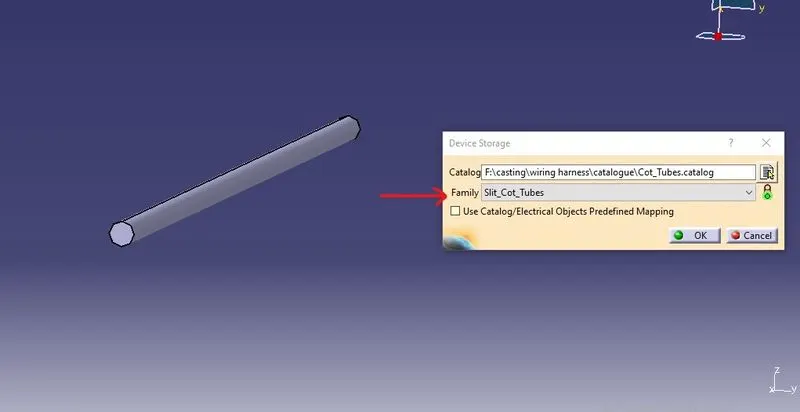
for storing the cad parts the storage option and giving the location of the catalog file in the catalog option and choose the required family in the family tab.