Week 8 - Challenge 1 - Base Bracket Design
ans 1
Detail Report of Base Bracket
Steps for the Tooling Axis(bisecting method)
step 1 = Checking the connectivity of the input(class A surface) to ensure no gap between the surface.
1st we can check by simple visualization process.
2nd By using the joining tool = by clicking the joining tool and selecting the required surface onto which we require to check connectivity.
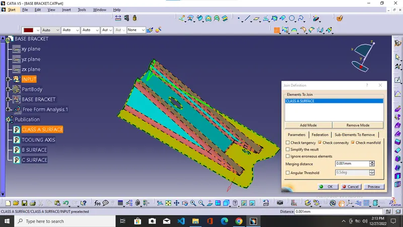
3rd By using Boundary definition tool by clicking the surface A after using the Boundary definition tool.
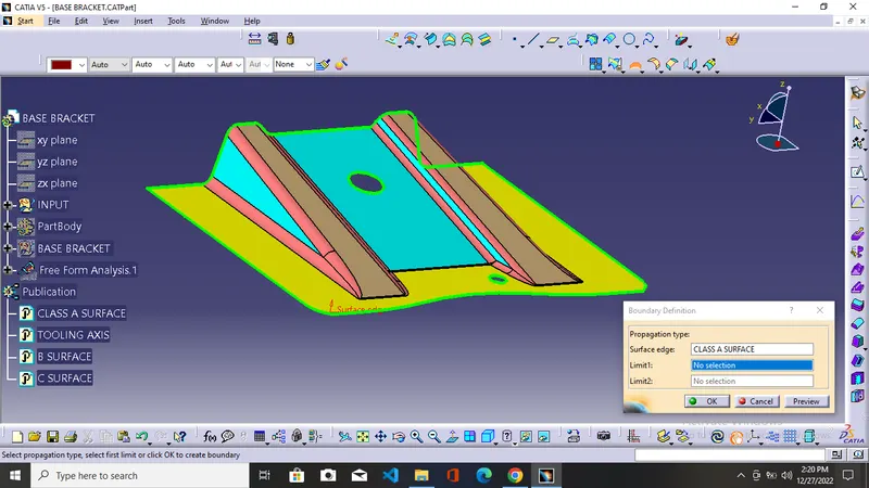
we can use any of the above three methods to ensure a fully connective surface.
step 2 = In this step we require the tooling direction we generally select that axis which requires minimum or no side cores to minimize the manufacturing cost.
in this part for the x-axis
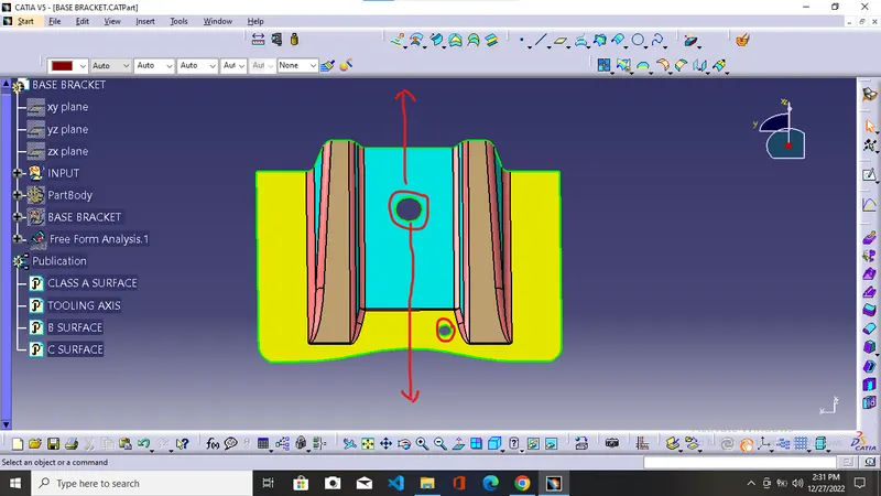
holes are present which require a side core so we did not select the x-axis.
The Y-axis
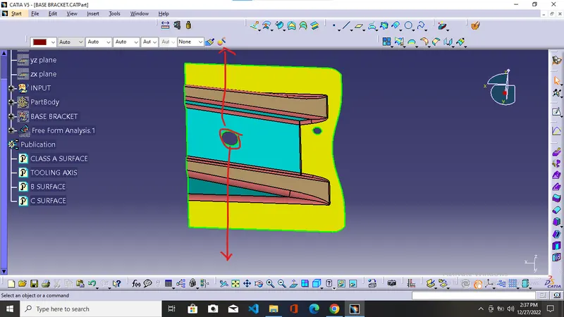
so holes are again a problem here so we did not select this axis also.
The Z-axis
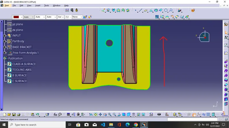
in this axis we can easily remove the part without the requirement of a side core.
so we 1st create the dummy tooling axis we can either choose the big flat surface or holes. In this problem, we choose the upper holes for the making of the dummy tool axis.
1st we create the midpoint for the hole by using the point definition tool.
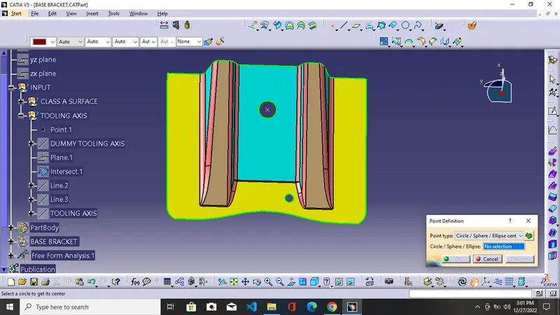
and then create the line with the above point as reference and z as direction
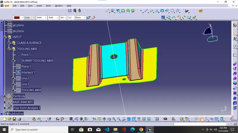
after that, the faces which are parallel to the dummy tooling axis may cause some problems when ejecting the part so for that we require a profile along the y-axis as the x-axis component is perpendicular to the z-axis and does not cause any problem. for that, we project a plane in parallel to the y-x plane and point 1 as a reference. and intersect surface A with the required plane.
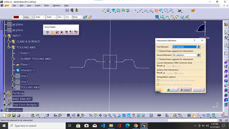
after that choosing the line which may cause the problem in the future and extending those lines and using the bisecting line option for bisecting the line. 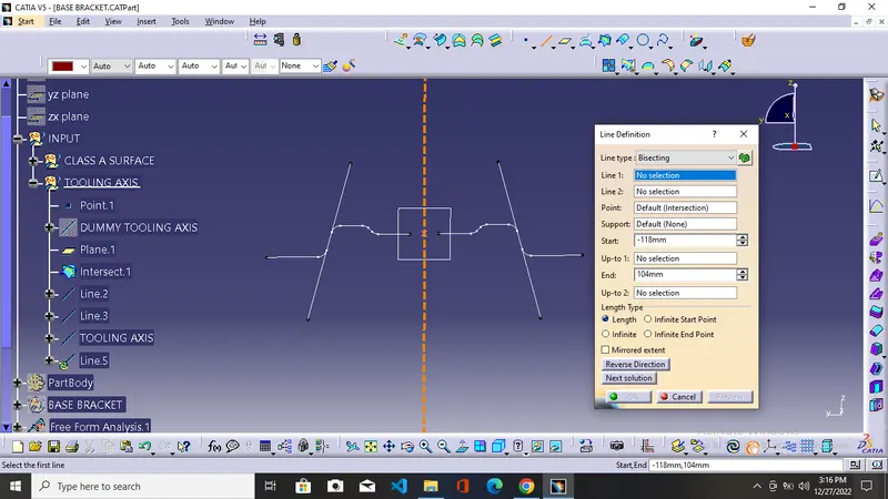
the required line is the main tooling axis.
Draft analysis
step 1
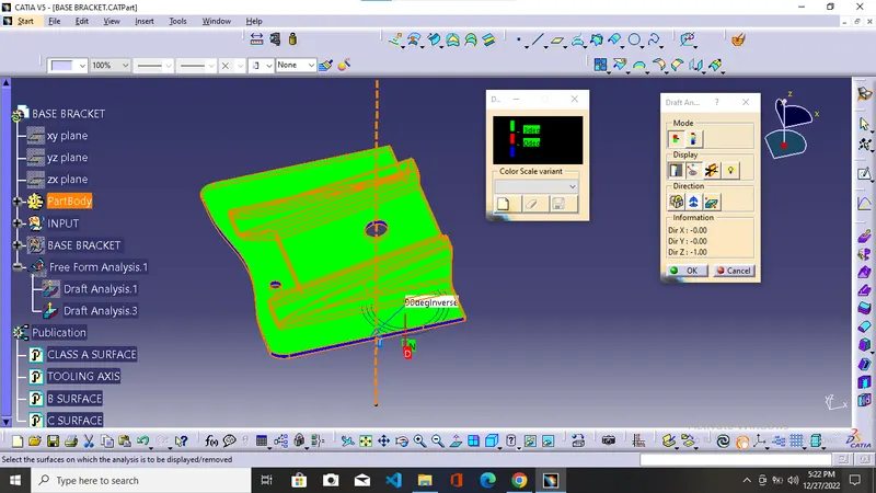
For the analysis, we use the draft analysis tool to check the required part has the minimum draft angle along the tooling axis. for that after clicking on the draft analysis tool we choose the compass option to get the compass and set the compass w direction along the tooling direction.
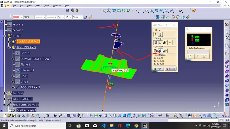
and lock the draft direction using the lock tool.
step 2
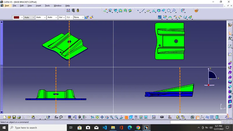
after locking the direction click on the part surface which provides us with the color code red and gives the information of o degrees green gives the information about the minimum draft angle generally 3 degrees and blue gives the negative angle. the surface which comes out green means their angles are greater than the minimum draft angle while the red means it is in-between 0-3 degrees so we need to work on the parts and try to again choose an axis for which the whole part comes out in green.
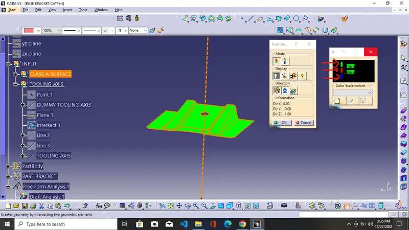
We can change the value of Red blue or green values according to our requirements. if every surface comes out green then it is a go signal we can proceed further for the B surface. We can click ok and save the result for further use.