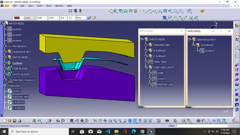
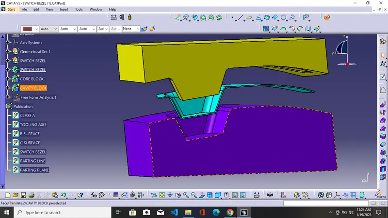
Week 8 - Challenge 6 - Core & Cavity Design
ANS 1
Tooling axis = It is the direction along which the mold opens for easy ejection of the solid part.
Number of processes to select Tooling Axis
- By making tooling axis along the X, Y, and Z axis
- By making the tooling axis normal to the part surface
- By using the bisection method
We can use any method but for the easy and fast process we go in order as mentioned above and once we find the out tooling axis we need not go any further. We are going to explain making tooling axis by NORMAL TO SURFACE method.
STEP 1 =Selecting the surface along which we need to create the tooling axis.
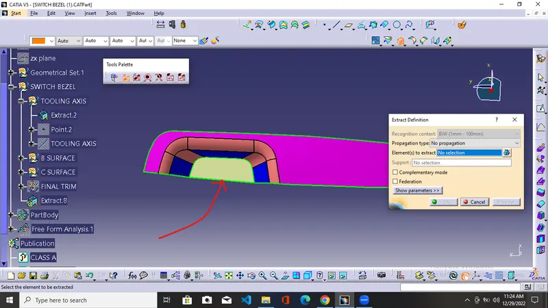
STEP 2 = Creation of point using the point tool using the option on the surface. select the extracted surface and give 0mm in the distance option to create the point in the middle of the surface.
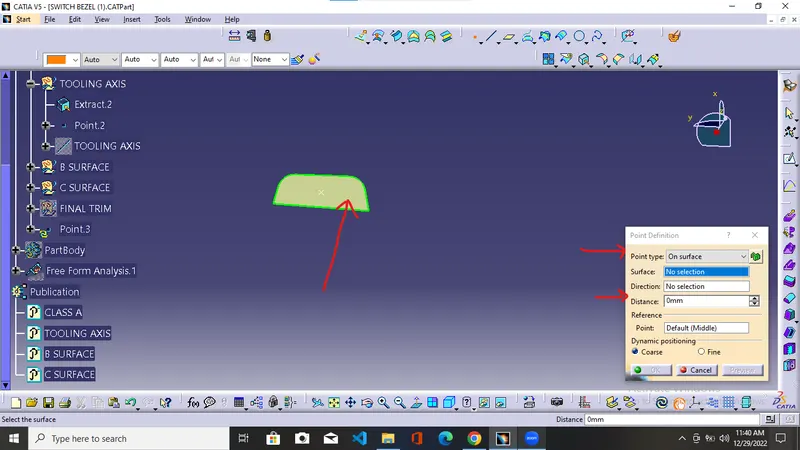
STEP 3 = Creation of the required tooling axis using the line tool and selecting the normal to surface option to give extracted surface in the reference surface option and the previously created point in the reference point option and obtain the required tooling axis.

DRAFT ANALYSIS = It gives us information about the parts which tells us which part clears the mold walls easily so as to minimize the machining process in the finished product and final product ejected easily and minimize the contact between the product and mold walls.
STEP 1 = Select the Feature draft analysis tool and move the compass to the tooling direction and align the compass w axis to the tooling axis. After aligning the compass with the tooling direction again click the compass tool to insure the proper alignment of the w-axis with the tooling axis. After the proper alignment uses the locking tool to lock the compass with the tooling axis.
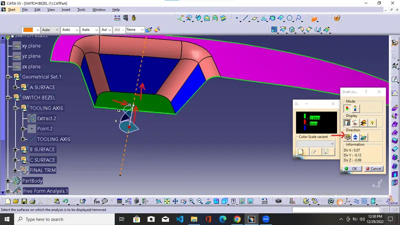
STEP 2 = Click anywhere on the A surface to generate the draft analysis report and use the quick analysis mode option to see the color code values where the green color defines the parts which have a draft angle greater than the green color code value generally it is up to 3 degrees in values. The red color gives information about the parts which have angles between 0 to up to a green color value which is generally up to degrees. The blue color gives information about parts that have an angle less than the red color. If A surface comes out in green color means our tooling axis is perfect and we are ready to go for the formation of B and C surfaces.
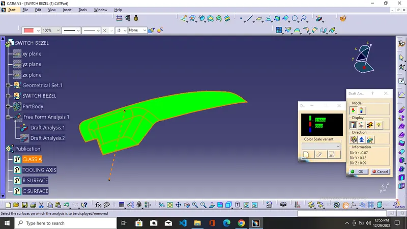
The final draft analysis report
step 1 = After trimming the close surface of A+C with B surface and getting the solid surface and repeating the same steps as we did in the analysis of A surface it comes out in green color without any red patches then our part is within the set parameter and comes out good.
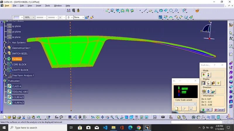
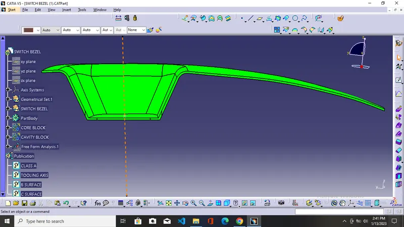
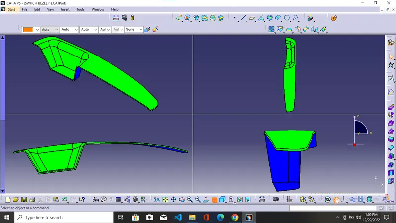
CORE AND CAVITY
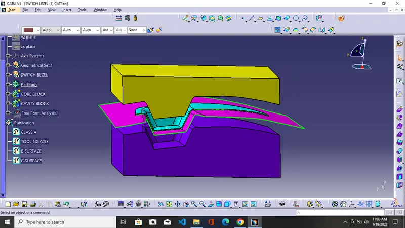
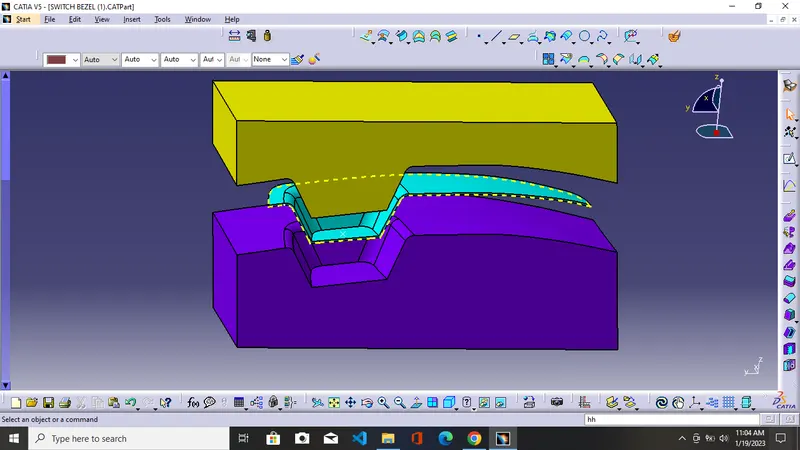
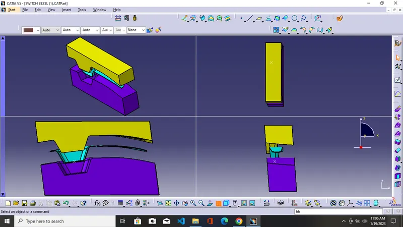
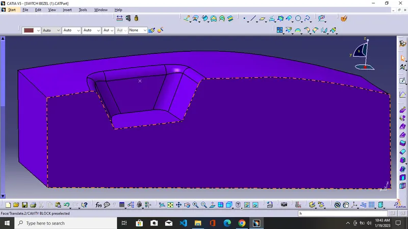
The core and the cavity are two respective halves of the mold. They together form a mold into which molten metal or plastic flows in it to form the required product.
CORE
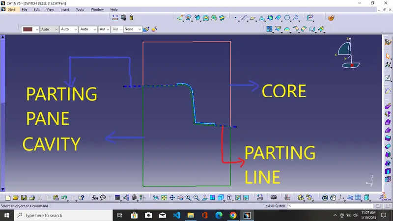
It is generally the moving half of the mold which has a projection.
CAVITY
It is the other half of the mold which has a depression in it.
PARTING LINE
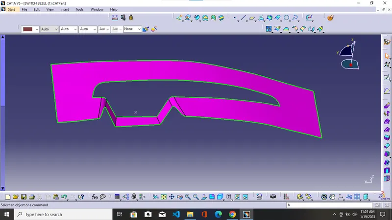
It is the line that lies generally on the B surface it indicates where the core and cavity meet. It is the line of separation on the part.
PARTING PLANE
In the molding process when the core and cavity are pressed tightly to form a cavity to avoid melt flow leakage and maintain certain holding pressure, the pressed surface is called a parting surface, usually parting surface is the biggest projection outline of the part.
CORE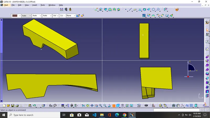
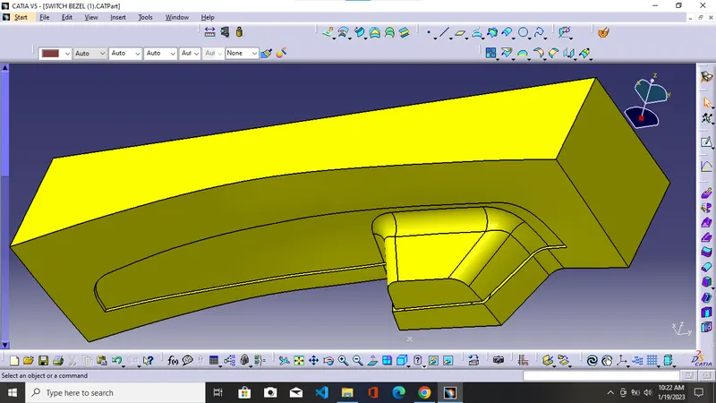
CAVITY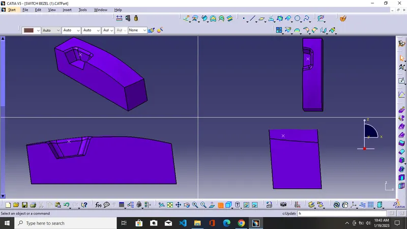
PARTING LINE 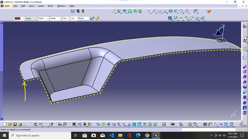
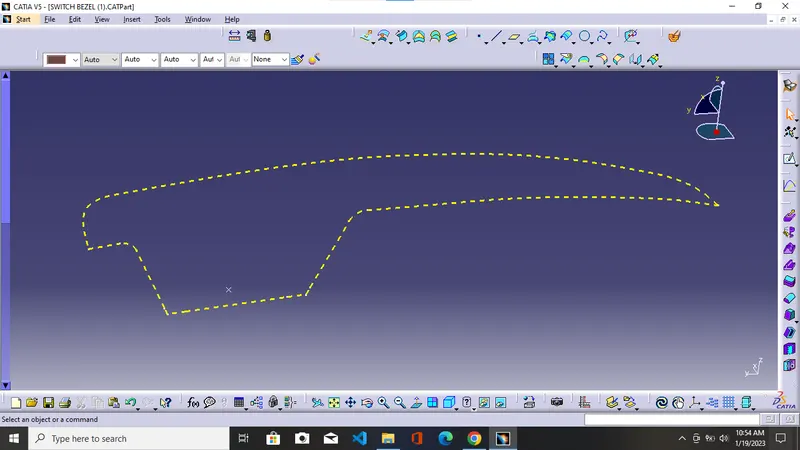
PARTING PLANE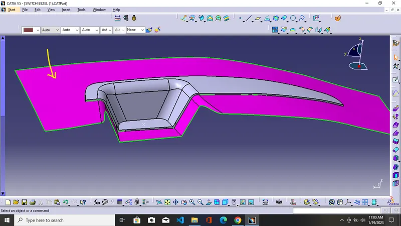
FINAL RESULT