Wiring harness routing & packaging Rules Week 3 Challenge
REPORT :
1.
AIM :
Define it as Electrical support using Electrical Part design Workbench. Define all the necessary properties.
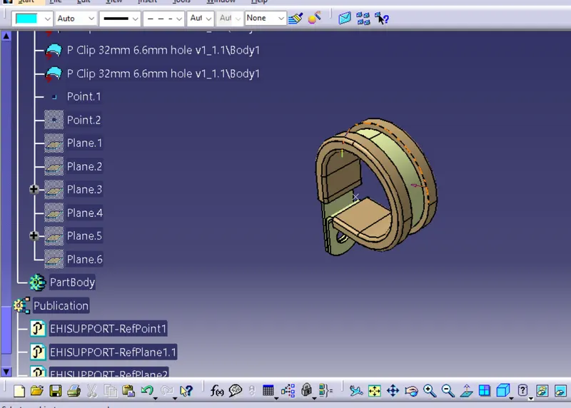
1.DEFINE ENTRY POINT :
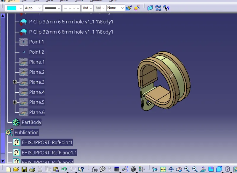
2.DEFINE EXIT POINT :
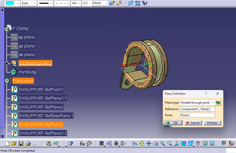
3.DEFINE ENTRY POINT PLANE :
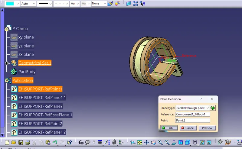
4.DEFINE EXIT POINT PLANE :
5.DEFINE BASE PLANE :
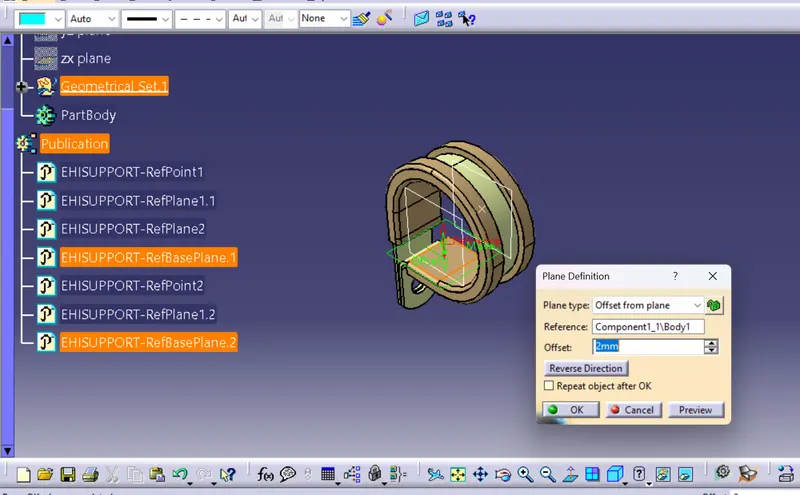
6.DEFINE SUPPORTS:
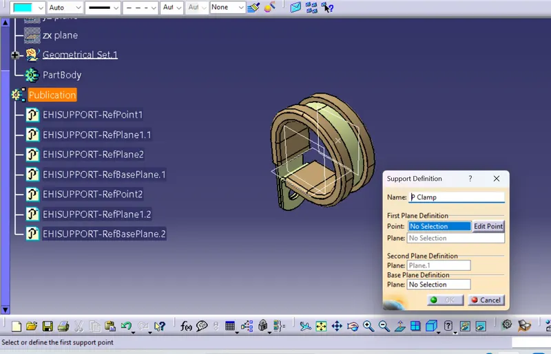
2.
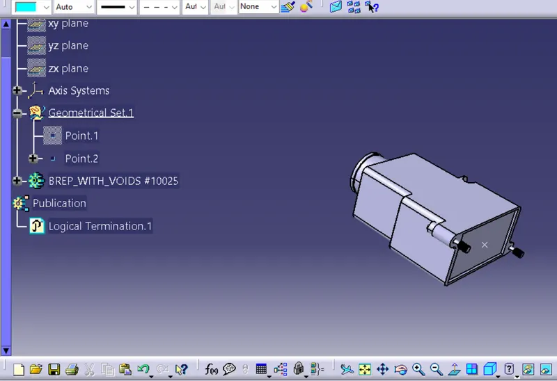
AIM :Download following Back shell cad data & define it as Electrical back shell using Electrical Part design Workbench.
1.DEFINE GEOMETRICAL PART FOR THE PART :
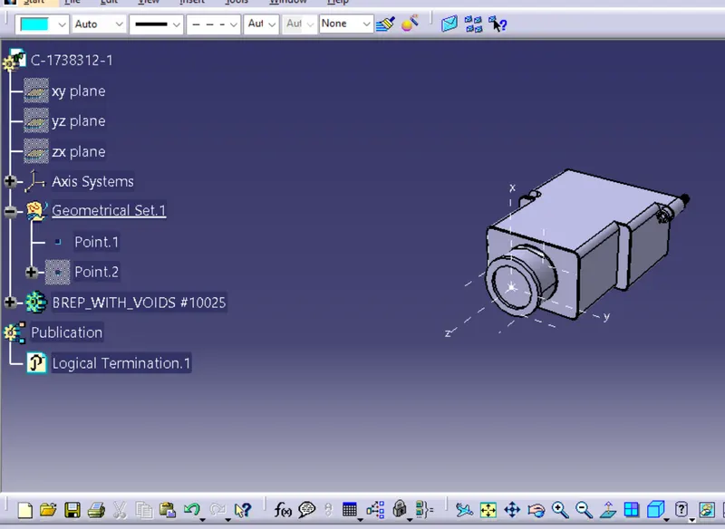
2.DEFINE ENTRY POINT :
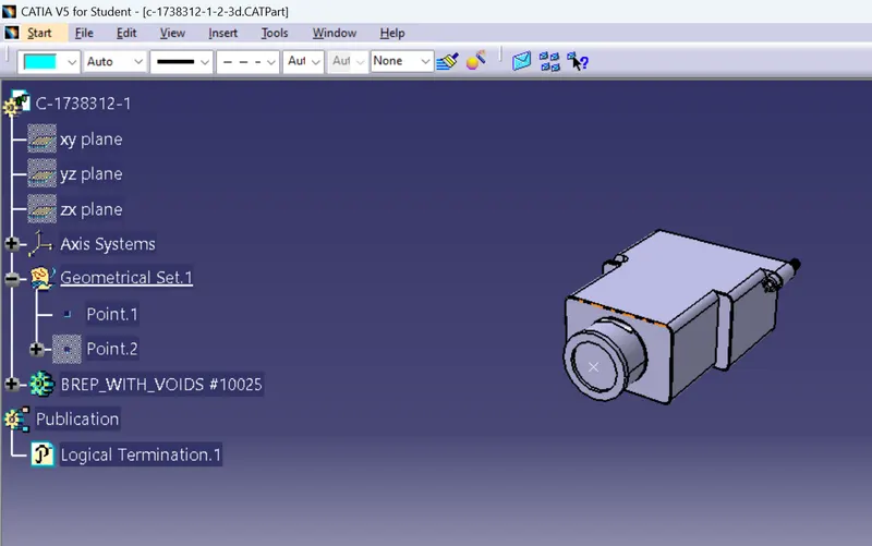
3.DEFINE BUNDLE POINT :
3.
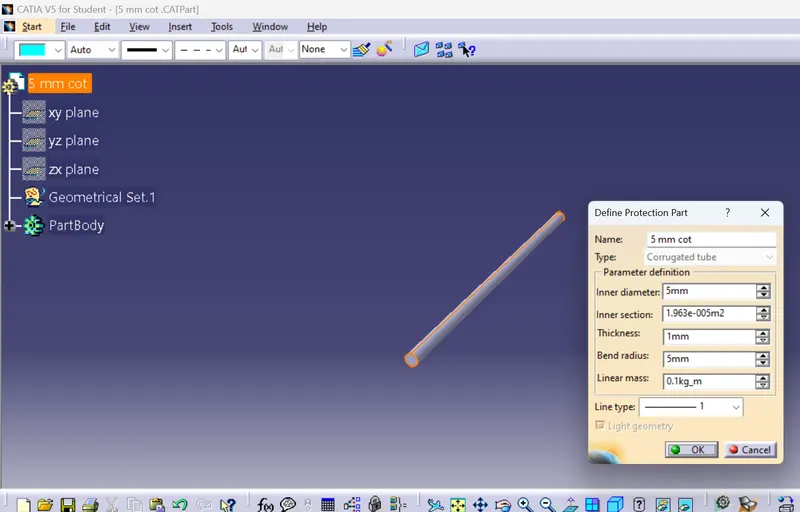
AIM: To create the corrogated tubes of the given dimensions
1.Add the corregated tube of requried thickness and length by using the define protection part has shown in the below figure
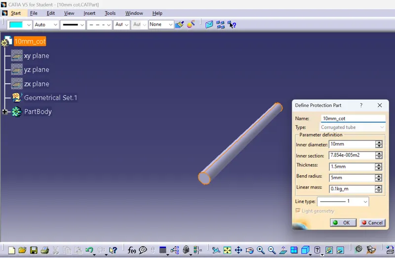
2.Add the protection part has agian as shown in the figure
3.Add the protection part has shown in the figure
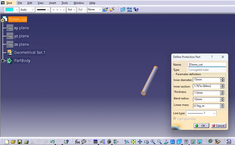
4.Add the protection part has shown in the figure
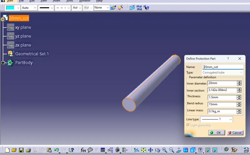
5.Add the protection part has shown in the figure

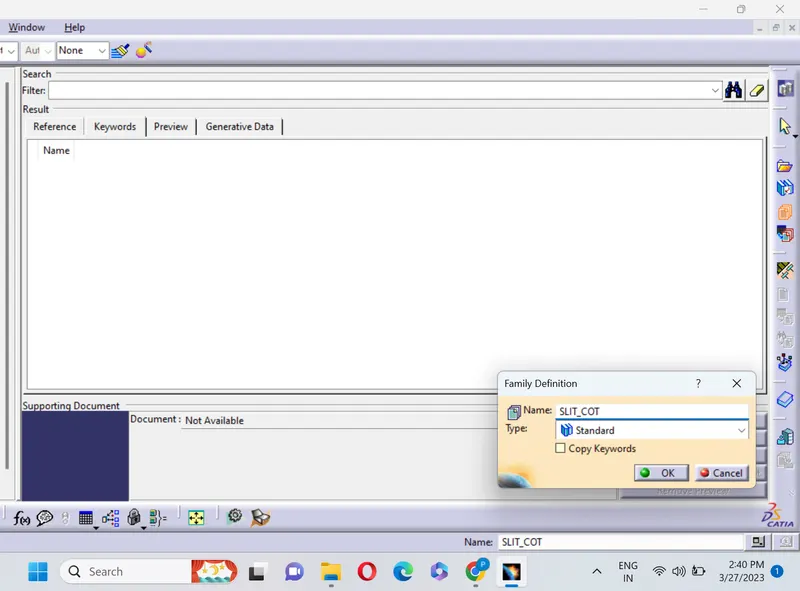
After creating the individual part bodies now create the catalog document has shown in the given figures

Now by clicking the add family tab you will see the below tab and modily the name has SLIT_COT and change the standard to contuide has shown in the below figure.
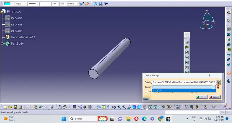
Now add the component to the catalog document by using the device storage option and select SLIT_COT that earlier created has the catalog document.
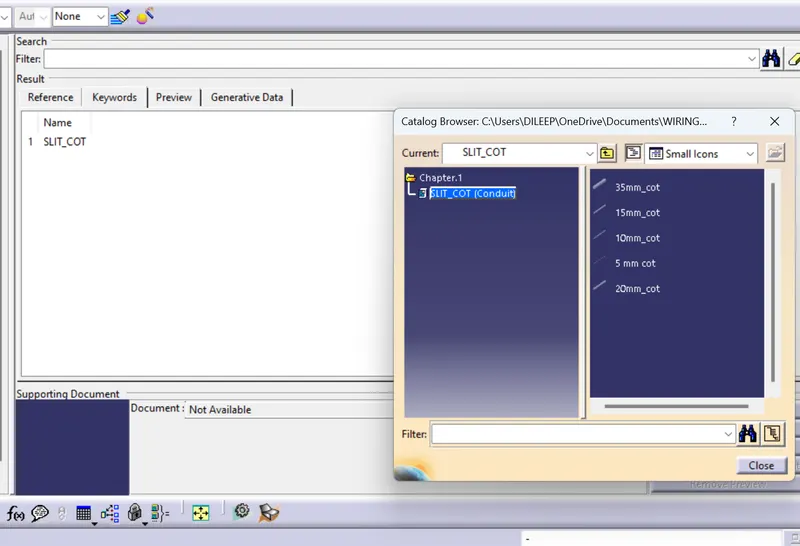
The below figure is the final representation of the all the individual bodies added in the catalog document
Conclusion : All the given conditions are hence fulfilled.