Wiring harness routing & packaging Rules Week 3 Challenge
Q1. CLIPS DEFINITION:
P clamps are very famous and it is widely used in the wiring harness assambly for firm fixing the wiring harness, It is also used to mount the hoses, hudraulic pipes, fuel line etc.
Here rubber protection is provided into it so that the metalic part of the p clamp does not damage the wiring harness .
1. We downloaded the part and open it in CATIA V5
2. Created a geometrical parameters: For creating this we have to define three parameters.
- Entry point & plane
- Base plane
- Exit plane
for creating this go to part dessign work bench create first point and plane paralel to the front fsaces and second point on the other side and a plane parallel to the second faces and a base plane with zero offset from the base
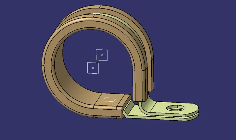
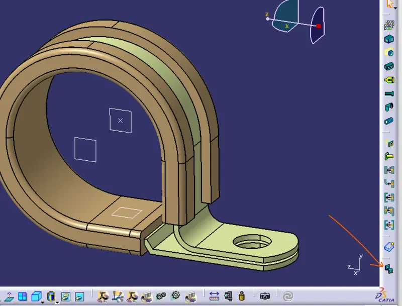
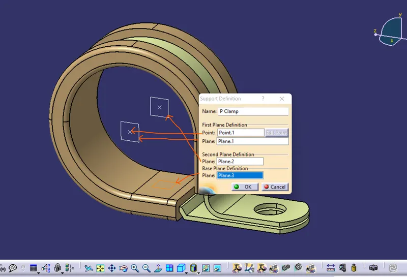
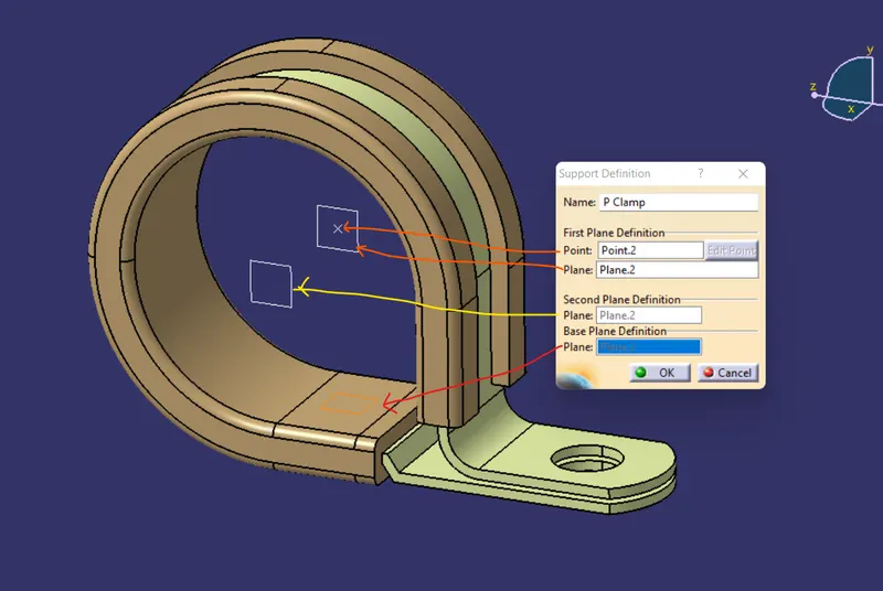
3. After creating all geometry switch to ELECTRICAL PART DESIGN WORKBENCH and go to defined support part see below image1 and a popup wimdow will bw open and provide here all necessary as defined in the below image2 and the click ok
1 2
Here the first plane will be treated as the entry point of the wiring harness and second plane as a exit point of the harness.
after this a process pont 1 will be hidden see below image
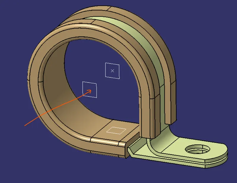
The clips has two entry point and two exit point in this case we need to defined properties two times to give a flexible to designer to selsct the clamp from both th bundle direction.
Again we we go to the Defined support part> click on part> a window will popup see below image here all red lines shows the new selectin from the same geometry here first plane will be as entry point from the opposite direction yellow colour shows it is automatic taken as the exit plane second plane
Below images showa that the clips now has fully defined
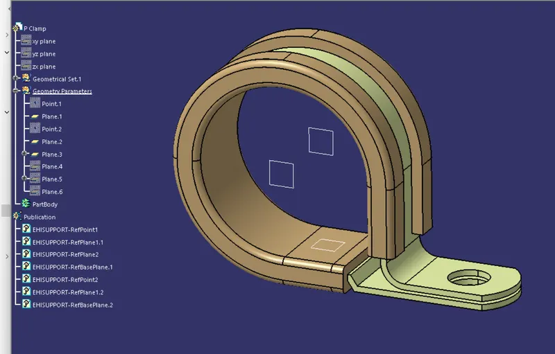
- CATALOG CREATION:
For catalog creation go to>file>new>calalogdocument see below image1>ok>add family see below image2>
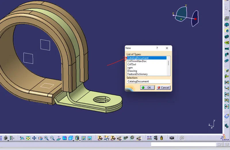
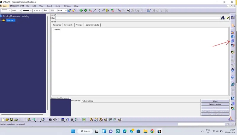
1 2
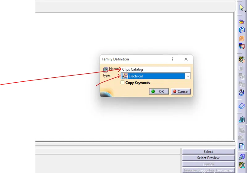
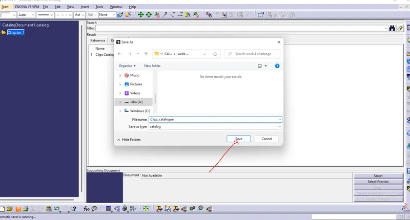
Now provide name and type: electrical see below image1>ok. now go to file>save >select folder>save with the proper name image2
1 2
MY catlog folder has been created now we have to add part on the same file
in electrical part design> store device below image1>catalog browser image2> select that file which we had just saved see below image 3 and 4.> in family select clips catlog.
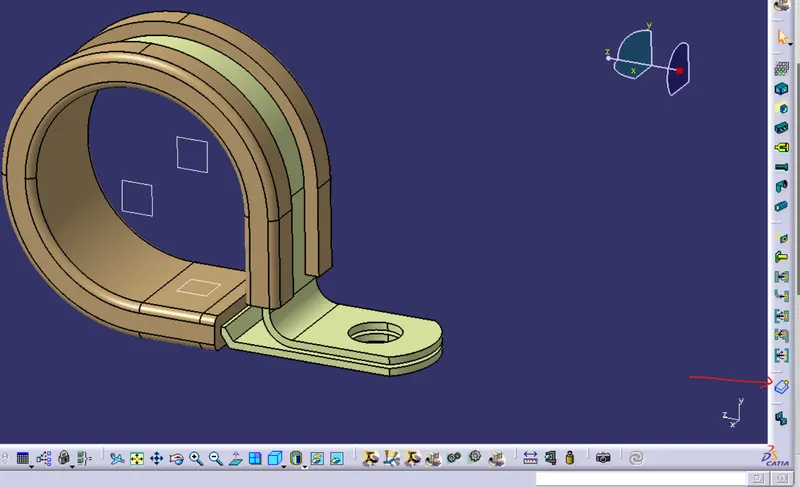
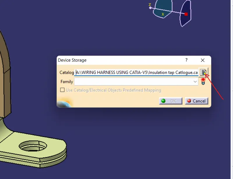
1 2
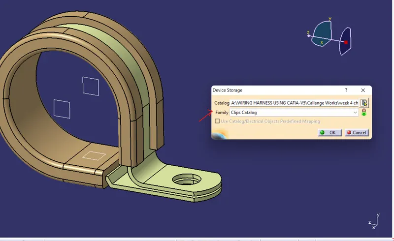
3 4
SO our part has been finally added in CATALOGUE.
Q2. BACKSHELL DEFINITION:
Backshell are plastic moulded part used at wire entry side of connector either for protection or to improve apppearance of harness
These are not amanadatory parts of wiring harness . The use of the backshell depends upon the cost you want to invest on wiring harness.
It is also used in case of very tight packaging area and it can not have the entry from both side as in case of clips , here only exit point is need to be defined as the geometry. below image shows the different types of backshell.
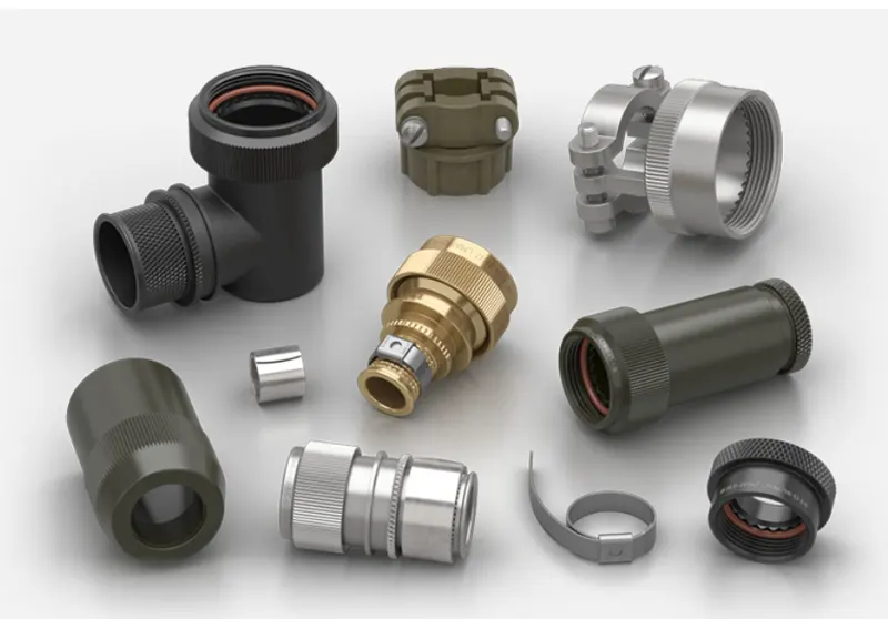
- Electrically Defined Backshell Process:
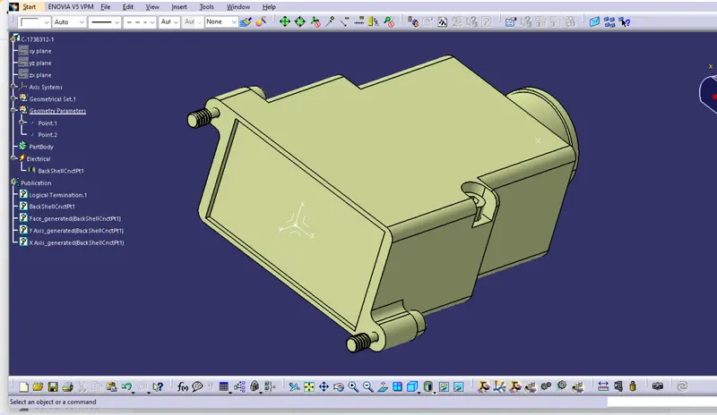
1. Defined the required geometry of the backshell as shown in the below image, the front point and axis systems defined the mating point with the connector entry point.
Ensure that methodology and logic to defind the point and axis system is same as connector connection system , ensure that defined axis and orientation should be identical with th mating parts.
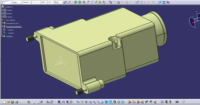
2 Switch to ELETRICAL PART DESIGN go to DEDINED BACKSHELL image1 >CLICK ON PART>a popup windoe will be open as shown in below image2 here you can edit part name and give extra length( if you want to move bundle ahead of your point then you can give extra length>OK
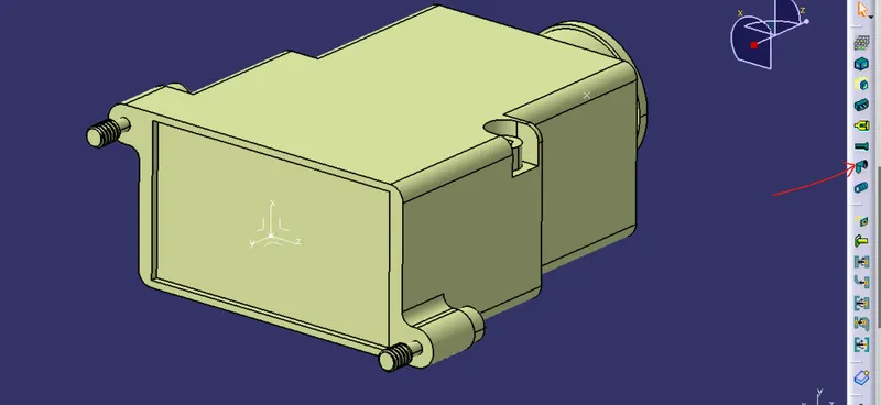
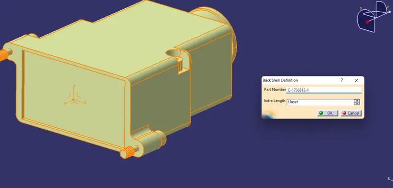
1 2
3 Nowgo to DEFINED BACKSHELL CONNECTION POINT(below image1)>click on part>here a popup window will be open defined it as all necessary shown in below image2>ok
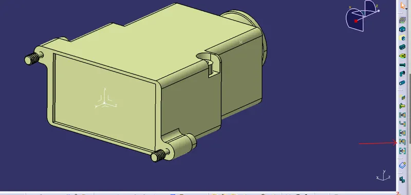
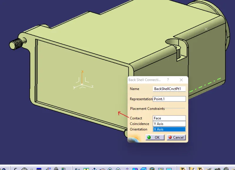
1 2
Here backshell is succedfully electrically dfined
- CATALOGUE CREATION:
For creating catalogue for the backshell we will follow the same process as discssed in above catalogue process for CLIPS'
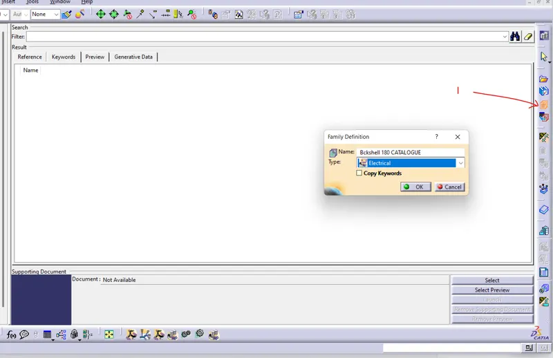
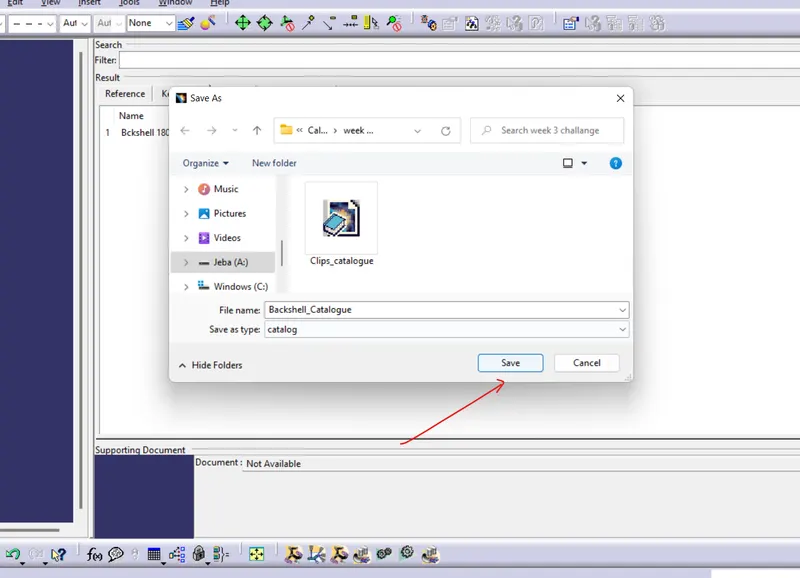
go to file>new>catalogue documents>ok>add family> give name and type as shown in below images2>ok>save this with name as shown in below images 2> close this window
1 2
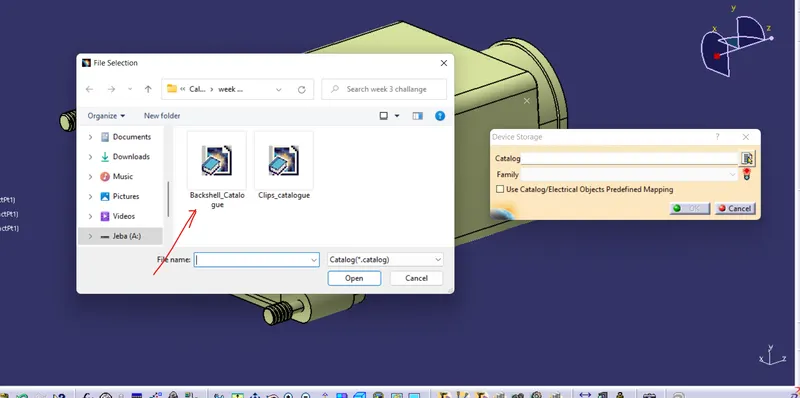
Now go to STORE DEVICE>catalogue> select catalog from file> family>ok catalog is fully created for the backshell
Q3. CORRUGATED TUBES
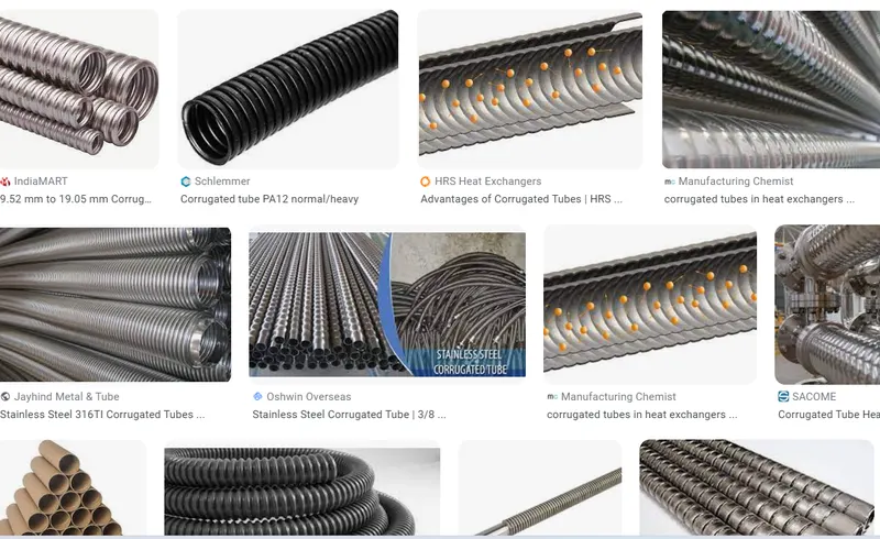
It is nothing but a act as protection for the wires known as PROTECTIVE COVERINGV.
Corrugated tubes, Convolutes, Sleeves and many other types of covering are used to protect the wiring harness , following are images shows different covering
For creating Corrugated tubes open new electrical part design give the required name as shown in below image1
> click on DEFINED PROTECTION PART see below image2>click on part body 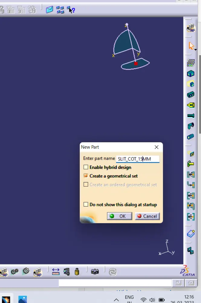
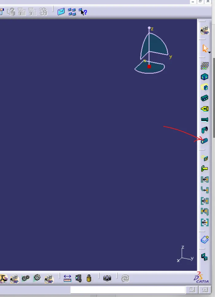
1 2
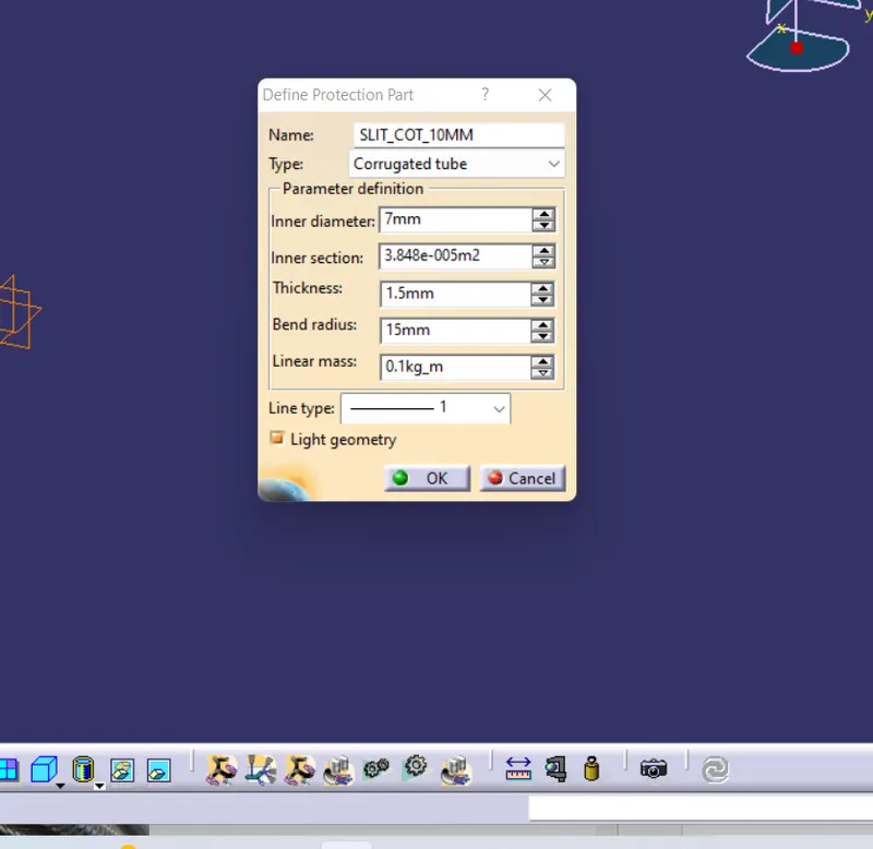
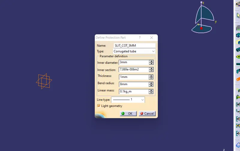
a popup window will be open as shown in below image2, in type>Corrugated tube, provide inner diameter, thickness,bend radius (it is generally 1.5 times of the external diameter of the tube)>ok
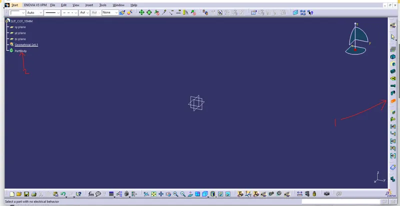
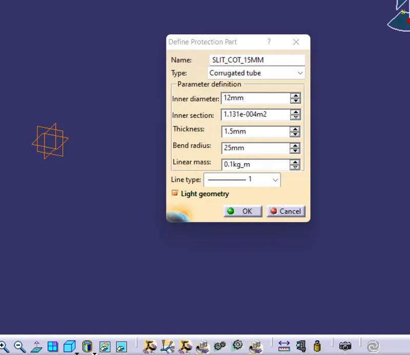
1 2
Similarly do the same for all CORRUGSTED TUBES images parameters are attached for the different tubes:
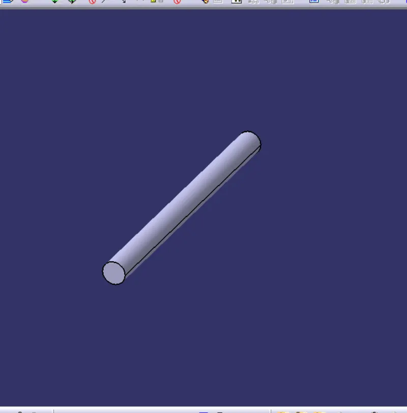
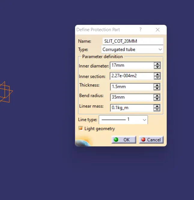
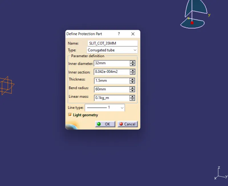
- CATALOGUE ADDITION:
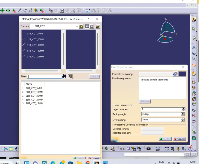
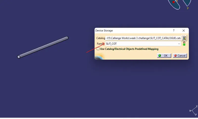
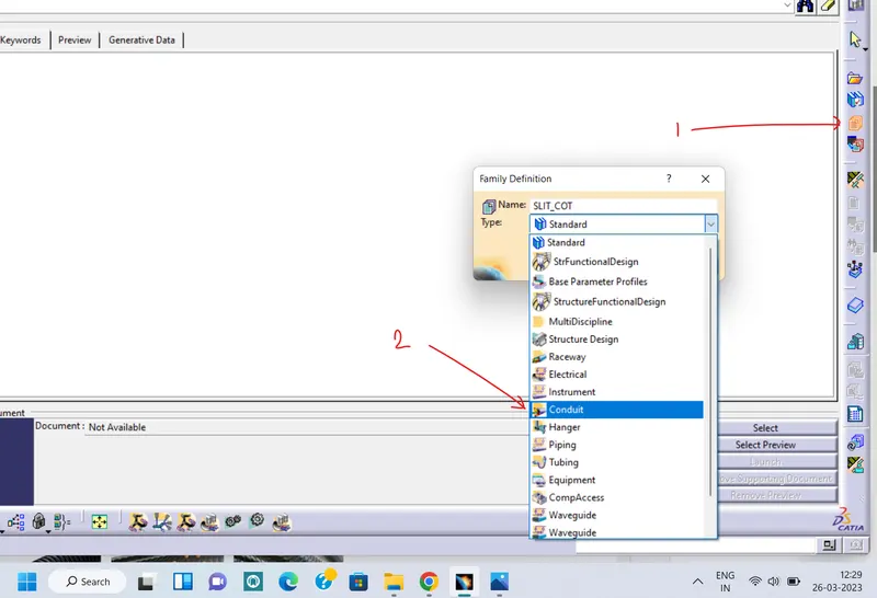
Go to file>new>cataloguedocument>ok>add family>here give the name and Type as CONDUIT see below image1>save it>close> open the corrugated tube>STORE DEVICES>select the same filee, family SLIT_COT see below image2>ok.
2 1
OUR ALL CORRUGATED TUBES HAS BEEN ADDED in the Sit_COT family see belo image