Week 8 - Challenge 2 - Switch Bezel Design
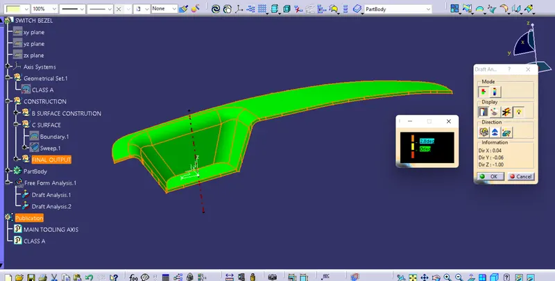
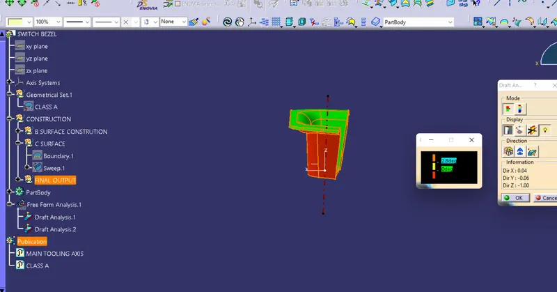
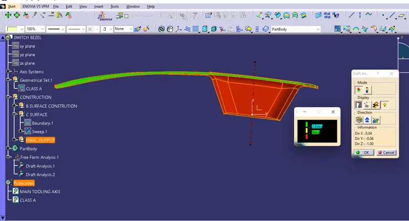
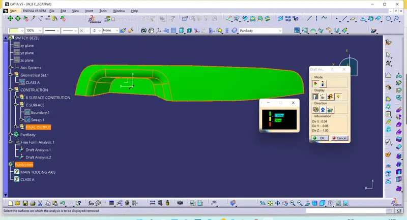
Draft analysis: draft angle is provided on component to ensure easy removal of the component from the core and cavity after it solidifies. In Catia v5 draft analysis is done for the component, First a tooling axis is to be created click on the featured draft analysis pic on the compass and drag it into the tooling axis and lock it then click onthe component here the different colore coding will dispalys which shows the differeng draft angle of the component with resspect to the main tooling axis. we can measer the draft angle manually by clickin on analysis under running point.
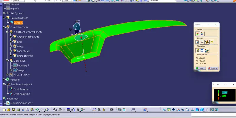
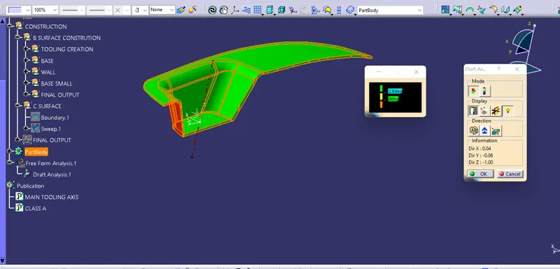
Creating the tooling axis: For creatingtooling axis first make an intersection line bitween the component yz direction and make the two line along this intersection curve the hide it then go to line bisecting click on this two point then ok this is the tooling axis for y direction. now create an intersection line between the component along zx direction, create a line along this intersection and a line from the point which is 3 degree fromm the previous line we can edit these angle later this is the toling axis for x direction now we have to create the main tooling axis, go to line bisecting click o these two axis and pont hence this is final and main tooling axis for the component.