Wiring harness routing & packaging Rules Week 3 Challenge
Wiring harness routing & packaging Rules Week 3 Challenge
AIM:
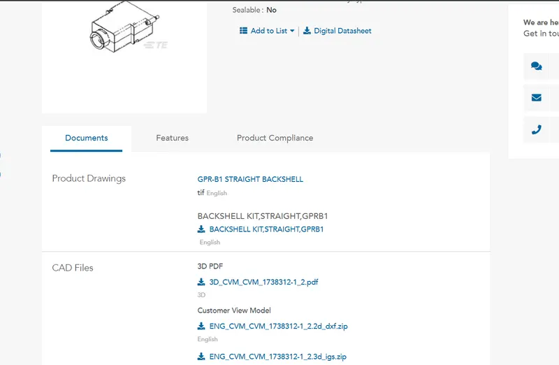
Download following CAD data & Back shell cad data from given link & define it as Electrical Connector using Electrical Part design Workbench. Define all the necessary properties to CAD data & Back shell. Create Following Corrugated tubes & Add them in Catalogue.
SOLUTION :
- We have downloaded the igs zip files.
- Extract and open in CATIA
- Save the files as CAD Parts

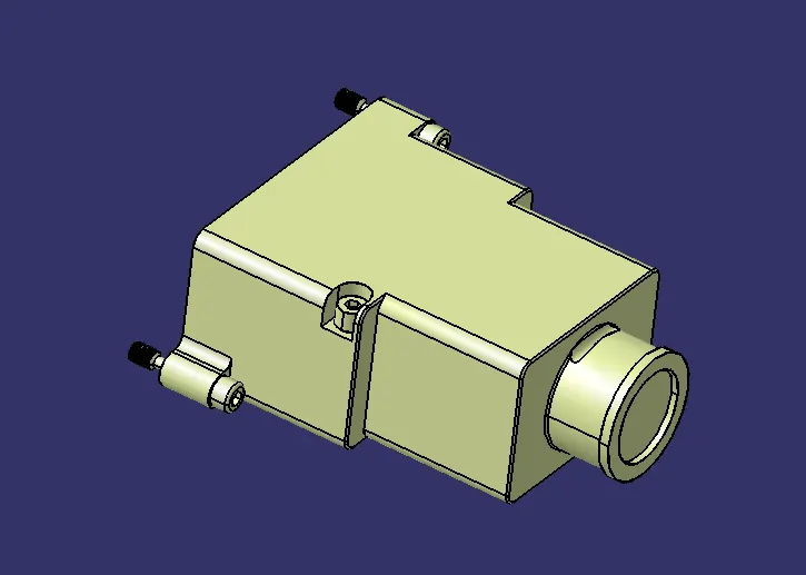
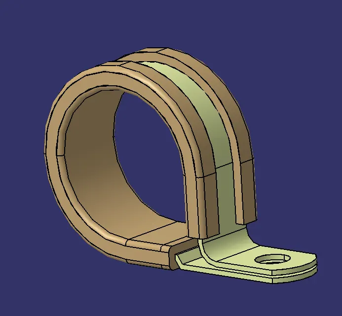
P Clamp
- Entry and exit point is created in part design
- Create plane at both the points
- Create a base plane.
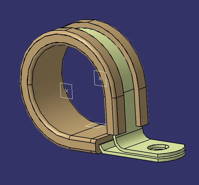
- Click Define support part in electrical part design.
- click the P clamp and define in both the ends
- Because bundle can be put in both the sides.
Tyco 1738312-1
- Create Bundle entry point
- Create Bckshell connecting point and axis for it.
- Align the Y axis away from the backsheel that can be used for coincidence
- Z and X axis on the other sides
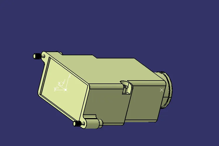
- Define the part as backsheel in electrical part design
- Create Bundle entry point on the bundle side of the backshell
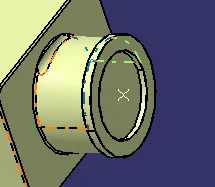
- Create Backshell connection point with representation as point and coincidence as Y axis
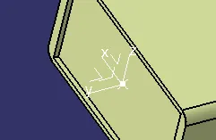
- Create a catalog and add the parts
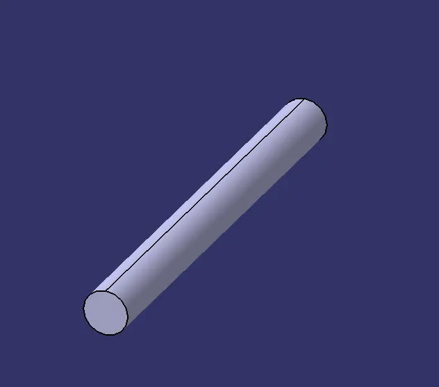
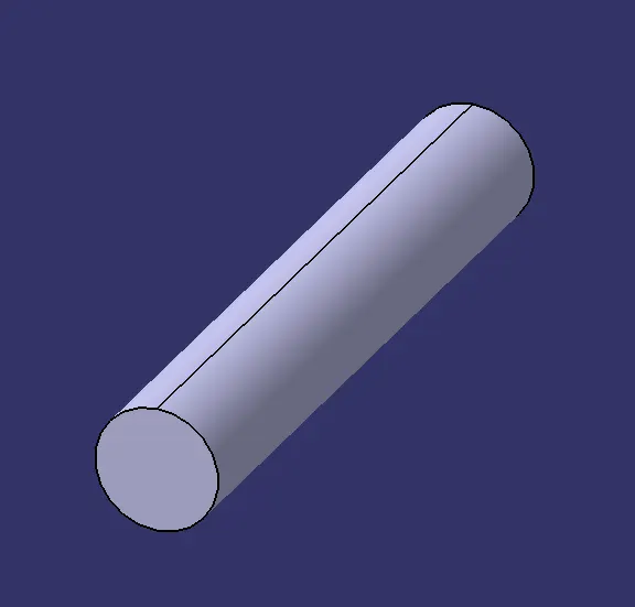
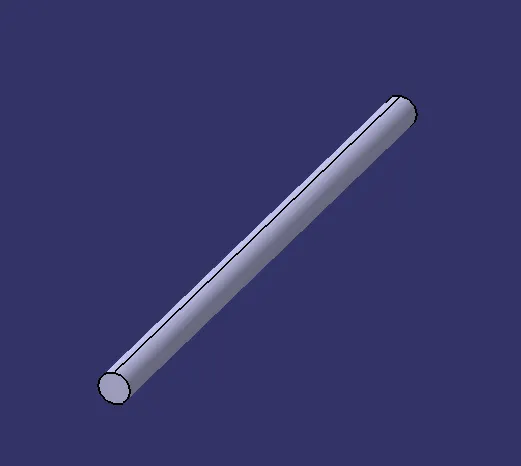
Create Following Corrugated tubes & Add them in Catalogue under “Slit COT” family.
|
Name |
ID (mm) |
OD (mm) |
Thickness (mm) |
|
15mm COT |
12 |
15 |
1.5 |
|
20mm COT |
17 |
20 |
1.5 |
|
35mm COT |
32 |
35 |
1.5 |
|
10mm COT |
7 |
10 |
1.5 |
|
5mm COT |
3 |
5 |
1 |
- Define protection part in electrical part design and click the part body.
- Enter the dimensions and create the COT Tubes

- Create a catalog and add all the COT Tubes
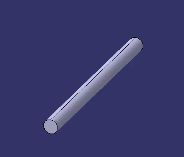
RESULT:
Hence we have Downloaded the following CAD data & Back shell cad data from given link & defined it as Electrical Connector using Electrical Part design Workbench.also Defined all the necessary properties to CAD data & Back shell. Created Following Corrugated tubes & Added them in Catalogue.