Wiring harness routing & packaging Rules Week 3 Challenge
' Wiring harness routing & packaging Rules '
Q1) Download following cad data & define it as Electrical support using Electrical Part design Workbench. Define all the necessary properties.
Clips are another important featue which needs to be defined before wiring housing routing and following parameters are to defined :
- Entry point & Plane
- Base Plane
- Exit Plane
Steps:
1) We have to create two points as one entry and another as exit point
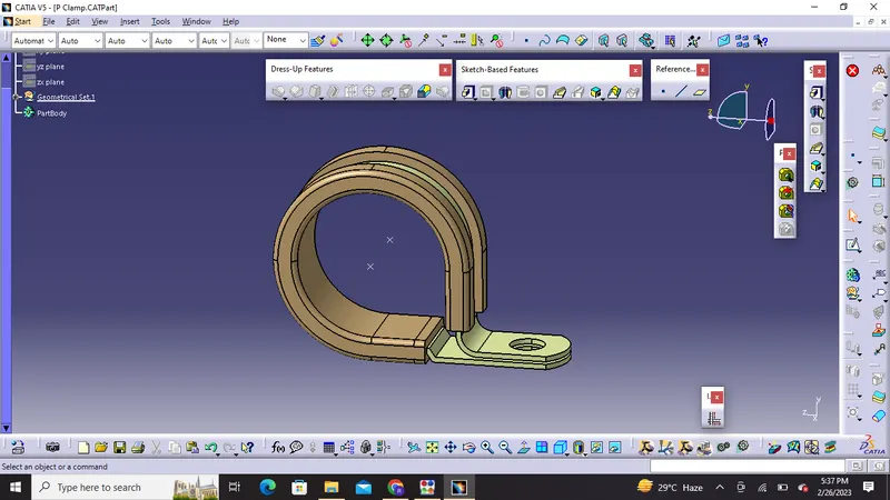
2) We have to create planes at two points and another at base
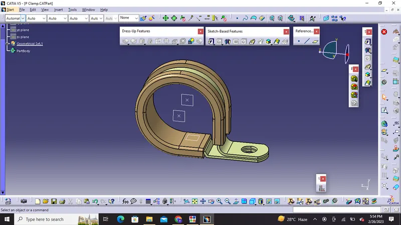
3) Then we have to switch to electric part design and click on support definition and complete the formalities like selection of part ,selection of entry point, selection of entry plane, exit plane and base plane.
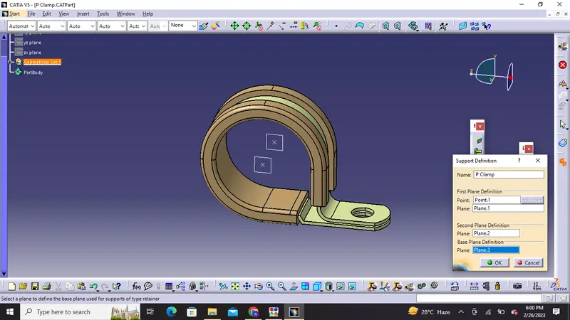
4) Furthermore we have to follow the same support definition from opposite side
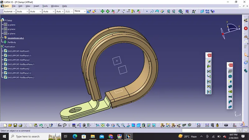
Hence we have defined it as Electrical support using Electrical Part design Workbench and also Defined all the necessary properties associated with it.
Q2. Download following Back shell cad data & define it as Electrical back shell using Electrical Part design Workbench. Define all the necessary properties.
A backshell (also known as an adapter) fits on to the back of a connector to provide strain relief and cable support to help from bending or over-flexing. It also adds an aesthetic look to connectors. Although these are not mandatory parts and are always optional and driven by cost.
Steps:
1) We will create a backshell entry point
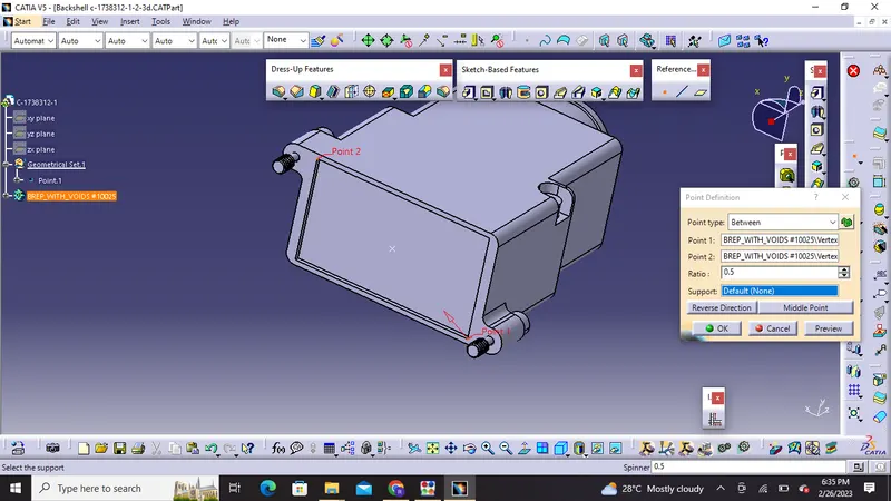
2) Next we have to create axis system for backshell entry point
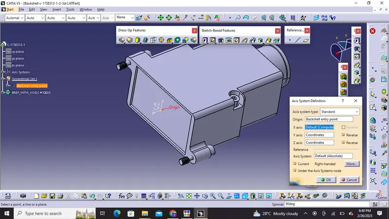
3) Next we have to create bundle connection point
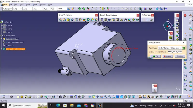
4) Then we have to switch to electrical part design workbench and define part electrically as backshell
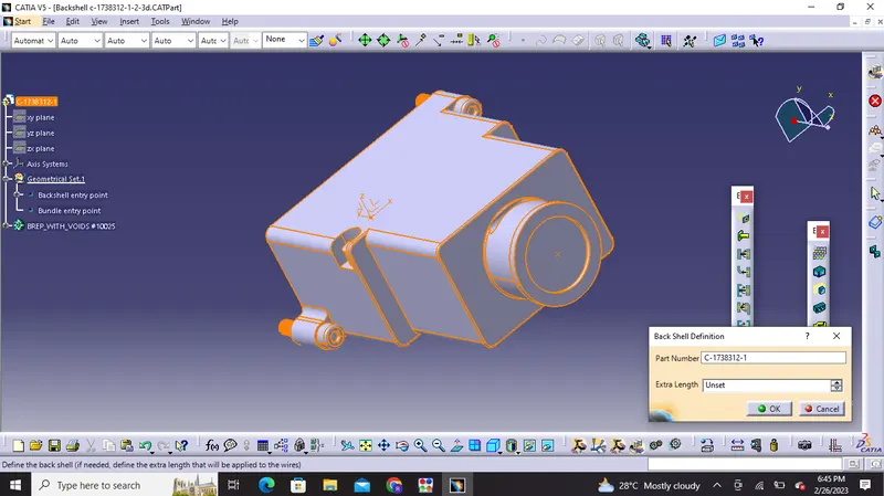
5) Furthermore we have to define backshell connection point
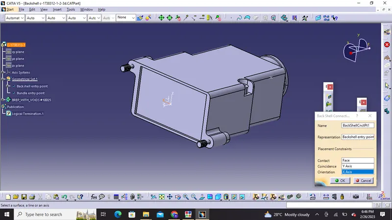
6) Finally we have to define bundle connection point
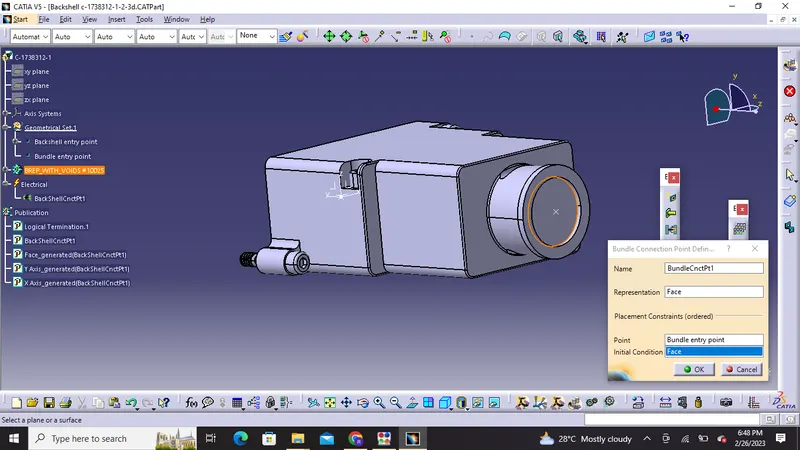
Thus all properties are fully defined
Q3. Create Following Corrugated tubes & Add them in Catalogue under “Slit COT” family.
|
Name |
ID (mm) |
OD (mm) |
Thickness (mm) |
|
15mm COT |
12 |
15 |
1.5 |
|
20mm COT |
17 |
20 |
1.5 |
|
35mm COT |
32 |
35 |
1.5 |
|
10mm COT |
7 |
10 |
1.5 |
|
5mm COT |
3 |
5 |
1 |
Steps to create Corrugated tubes:
1) we have to switch to electrical part design
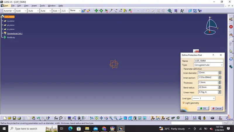
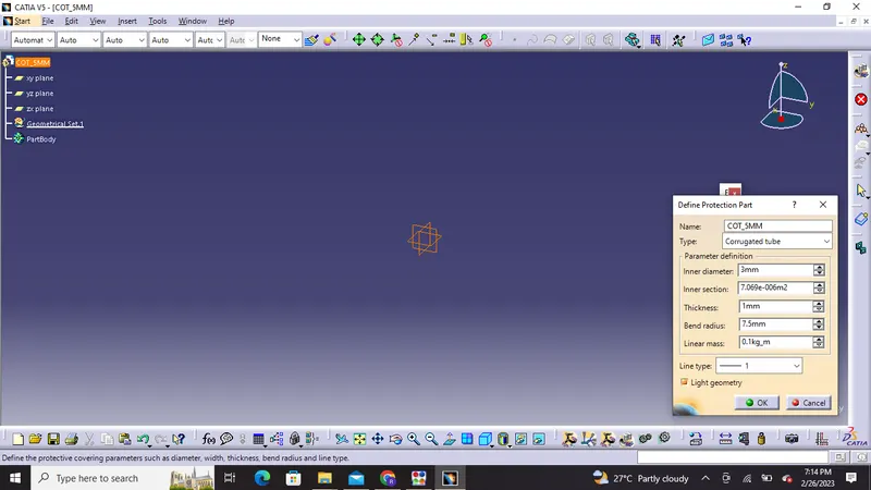
2) Then select Define protection part
3) Click on part in specification tree
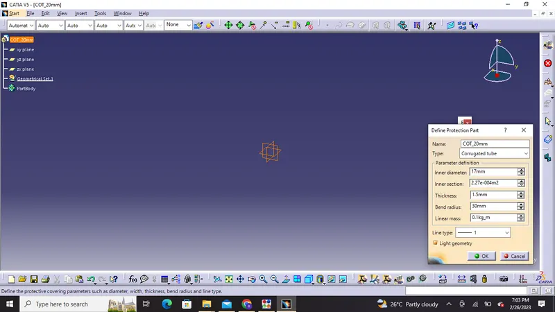
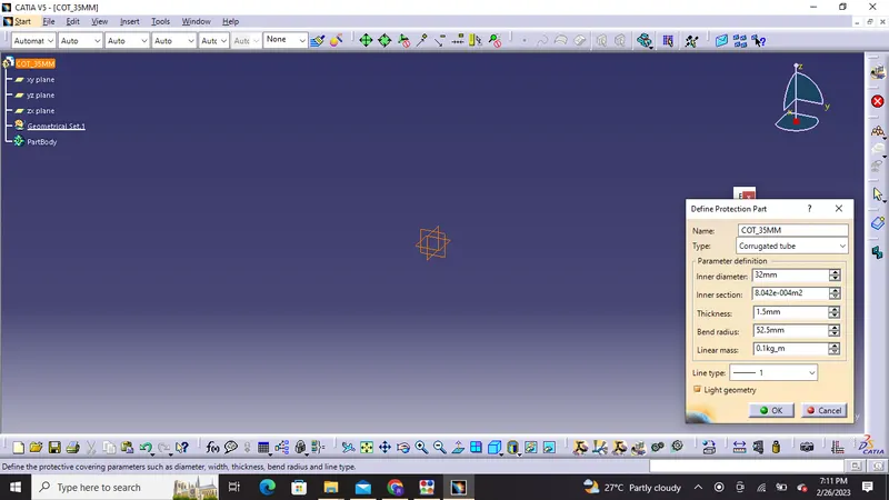
4) Then finally we need to provide the given parameters such as inner radius , bend radius and thickness etc '
#Note: Bend radius will be 1.5 times the outer dia of tube
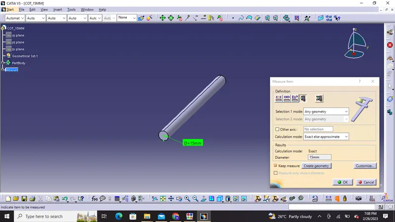
1) COT_15mm
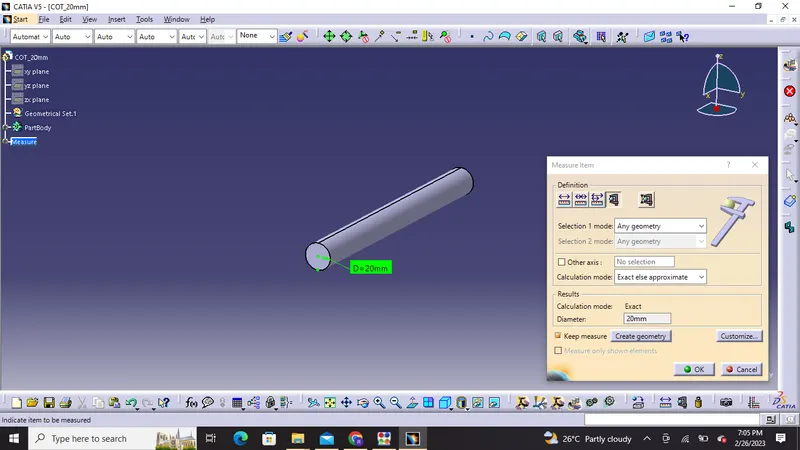
2) COT _20mm
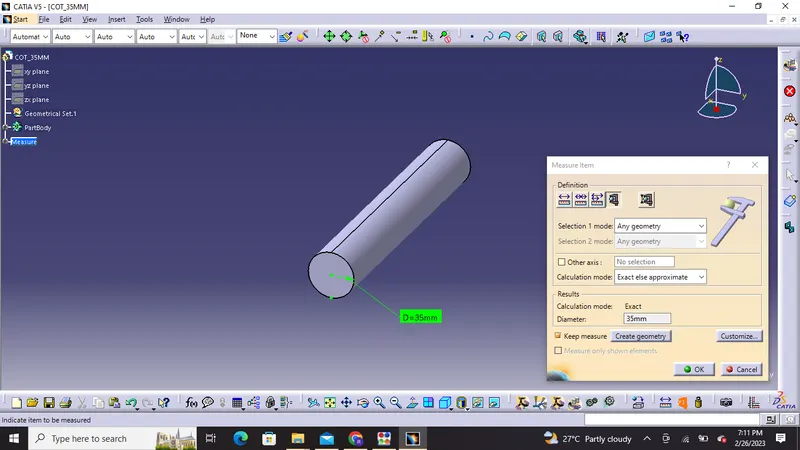
3) COT_35MM
4) COT_10MM
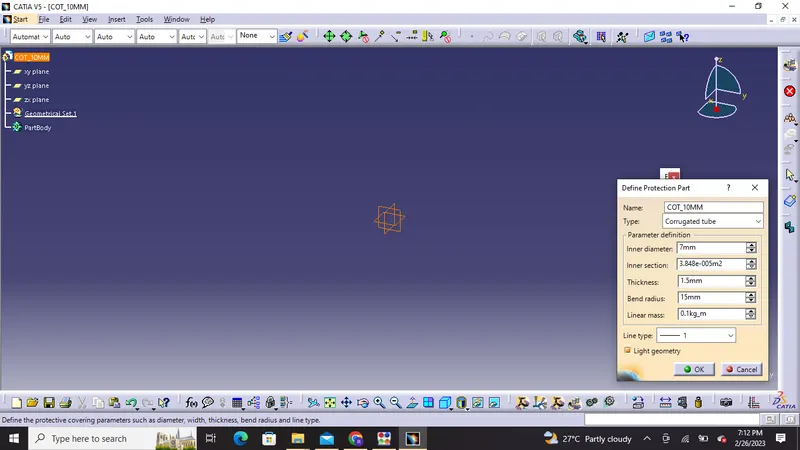
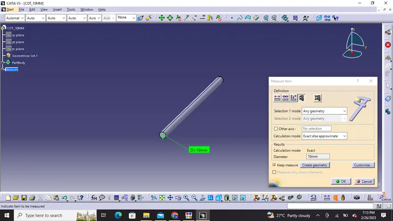
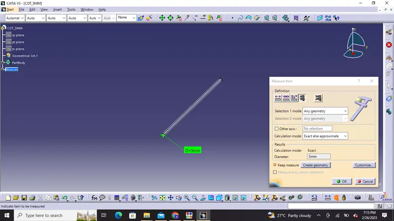
5) COT_5MM
Cataologue creation:
`1) We have to click on File-newpart-catalogue document-add family-given name-type-select conduit-save
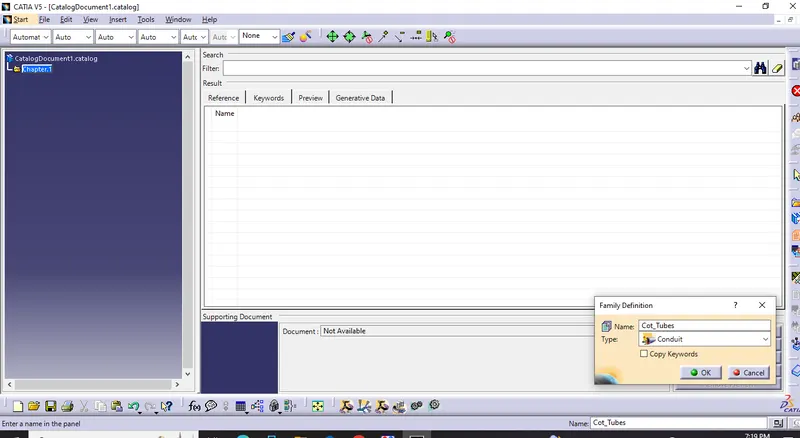
2) Then we have to Open part to add catalogue-storedevice-select catalogue-family-slit_cot_tube
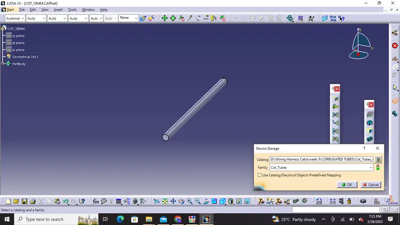
If we want to change any dimension of these tubes we need to select define protection part.
THANK YOU!