Wiring harness routing & packaging Rules Week 3 Challenge
Q1. Download following cad data & define it as Electrical support using Electrical part design Workbench. Define all the necessary properties.
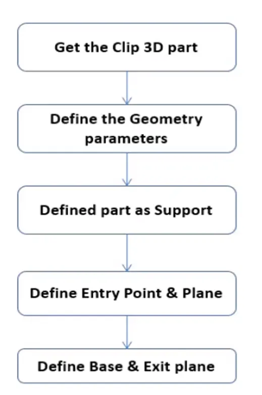
Steps.
- After downloading the file, use CATIA V5 to open it.
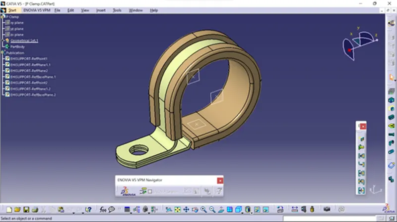
- In accordance with the part design model, entry, exit, base points and planes are defined.
- Open the files in Electrical part design once points and planes have been established.
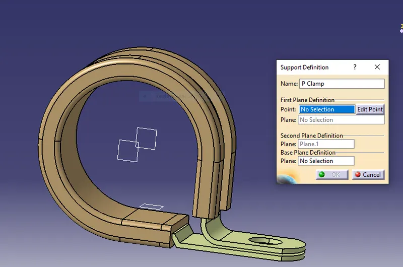
- Using the define support part command, we must now define the part as a support.
- Here we use the required point and planes as an entry and exit of the clamp for one side.
- Select the point opposite the initial support definition while maintaining the same base plane, and then utilise the support definition once more to provide an entrance point on the opposite side.
- After providing the necessary properties save the file.
P- clamp
Q2. Download following Back shell cad data & define it as Electrical back shell using Electrical Part design Workbench. Define all the necessary properties.
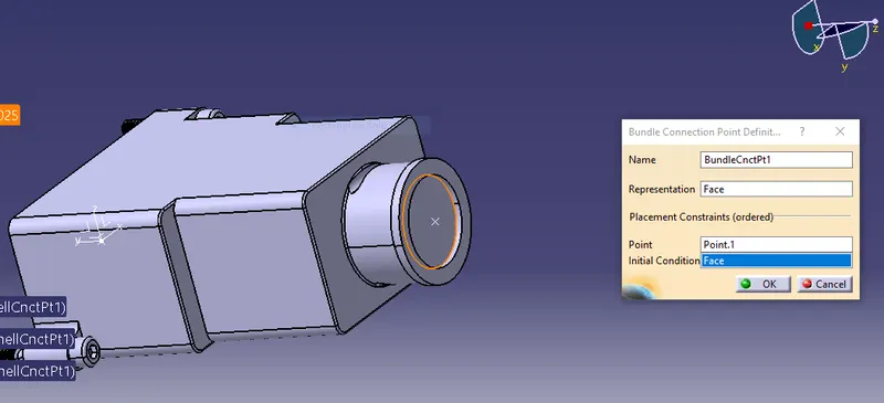
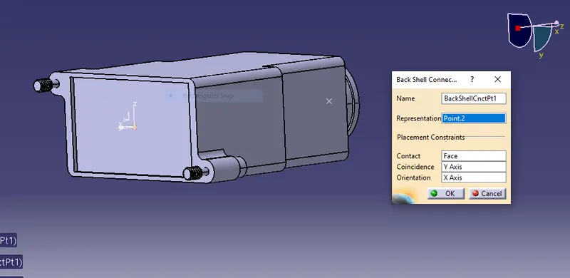
First specify the shell fixing point and the bundel entering point. Ensure that you also add the axis system to the fixing point.
The axis is in same direcation as of connectors.
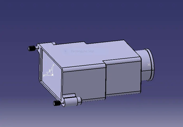
Define the shell as on electrical body
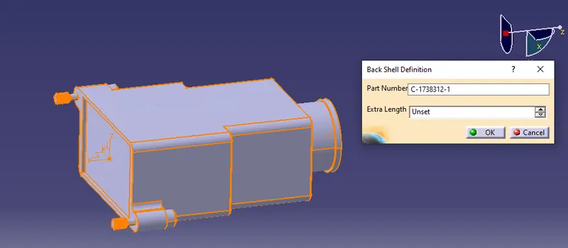
Add bundle entry parameter
Add the back shell parameters
Q3. Create Following Corrugated tubes & Add them in catalogue under Slit COT family.
Name ID(mm) OD(mm) Thickness (mm)
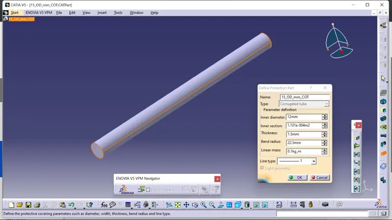
15mm COT 12 15 1.5
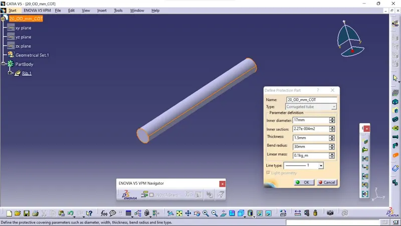
20mm COT 17 20 1.5
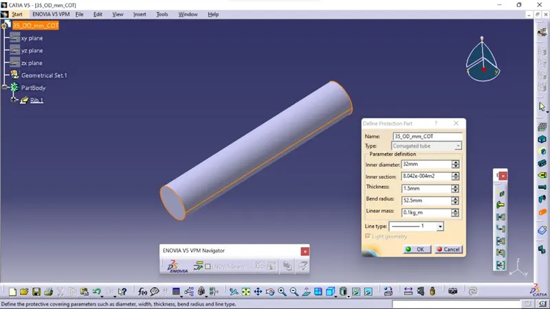
35mm COT 32 35 1.5
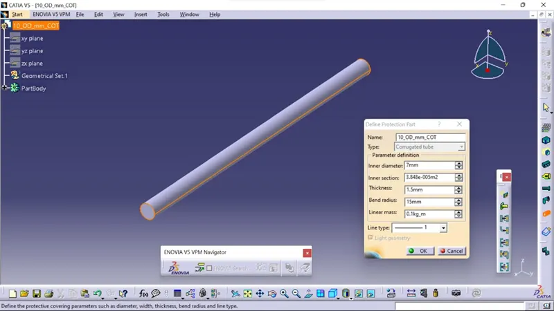
10mm COT 7 10 1.5
5mm COT 3 5 1
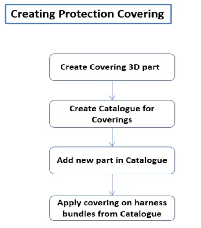
Steps.
- Open CATIA V5 with Electrical Part Design Model
- Using Define Protection part
- Select the type as Corrugated Tube
- Give the Required parameters ( Inner dia, Thickness, Bend Radii =1.5 times the OD)
- Click on OK
- After giving the necessary properties save the file.
15mm COT
20mm COT
35mm COT
10mm COT
5mm COt
Here are the solution of above question in answer body.