Roof Design
Question:
For the Given Roof styling, create an ASSEMBLY by developing the essential flanges for the outer roof and createing the reinforcements.
Provide appropriate dimensions and check for Draft analysis.
Do a curvature study on the roof and perform calculations to determine the position of the Bow-roofs.
Suggest and implement remedies in the design if the criterion is not full-filling.
Start with the creation of a roof ditch area with a tool opening angle of 7 degrees.
Develop the reinforcements as separate parts.
Bow- Roof Prediction formula:
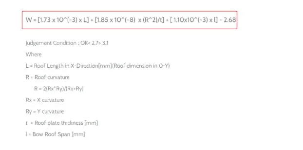
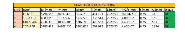
W = [1.73 x 10^(-3) x L] + [1.85 x 10^(-8) x (R^2)/t] + [ 1.10x10^(-3) x l] - 2.68
Where,
L = Roof Length in X-Direction [mm] ( Roof Dimension in 0-Y )
R = Roof curvature
R = 2(Rx*Ry)/(Rx+Ry)
Rx = X curvature
Ry = Y curvature
T = Roof Plate thickness [mm]
l = Bow Roof Span [mm]
Judgment condition
Ok,2.7
Snow Load prediction formula
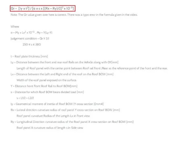
Qr = [Iy x t2] / [α x s x [(Rx + Ry)/2]2 x 10-8]
Note: The Qr value given over here is correct. There was a type error in the formula given in the video.
Where,
α = My x Lx2 x 10-12 , My = Y(Ly-Y)
t =roof plate thickness [mm]
Ly = Distance between the front and rear roof Rails on the Vehicle alongwith 0Y [mm]
Length of Roof panel with the center point between Roof rail Front / Rear as the front and rear reference point.
Lx = Distance Detween the Left and Right end of the roof BOW [mm]
The width of the roof panel is exposed on the surface.
Y = Distance Front Roof Rail to Roof BOW[mm]
S = Distance for which Roof BOW bears divided load [mm]
S = L1/2+L2/2
ly = Geometrical moment of inertia of Roof BOW (Y cross-section) [mm4]
Rx = lateral direction curvature radius of roof panel Y cross-section on Roof BOW [mm]
Roof panel curvature Radius of the Length Lx in Front view
Ry = Longitudinal Direction curvature radius of the Roof panel X cross-section on Roof BOW [mm]
Roof panel X curvature radius of length s in Side view
Judgment condition
Qr ≥ 3.1
250 ≤ s ≤ 380
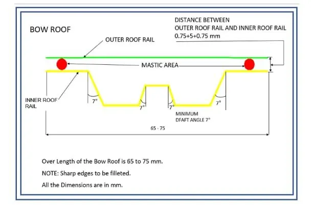
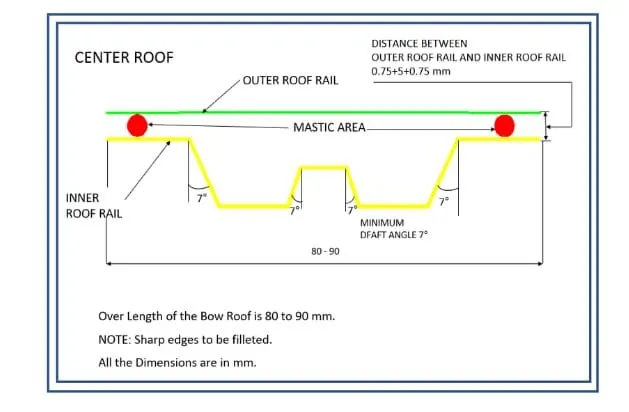
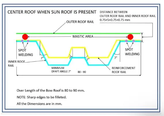
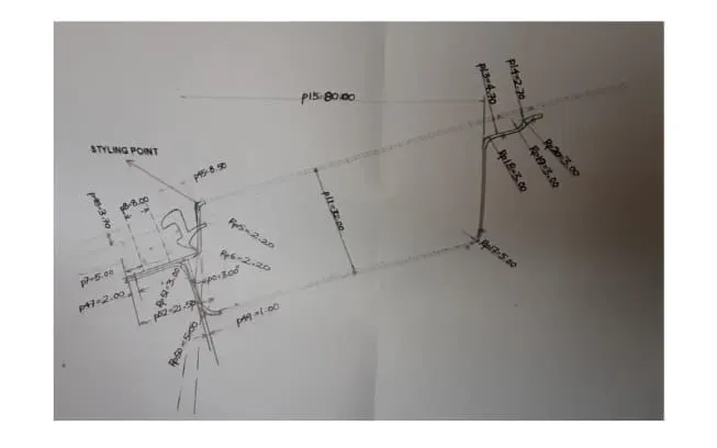
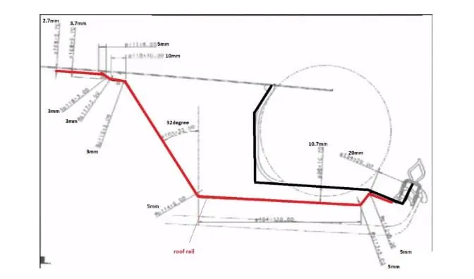
Here are some Reference images for the Master section- These images are just to give you a brief idea aboutthe design.
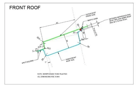
Front Roof Rail Master section
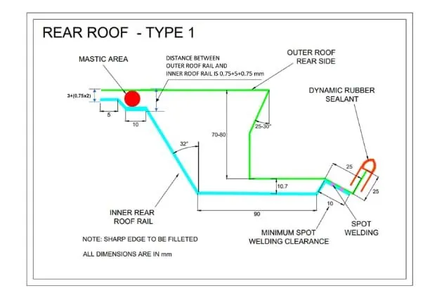
Master Section of the Rear Roof Rail
Master Section of Bow Roof
Master Section of Center Reinforcement Rail
Procedure and Excecution.
AIM:
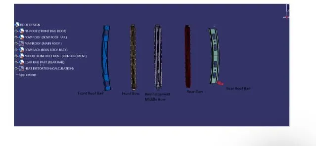
For the Given car roof styling, Design and develop the essential flanges and reinforcement, namely the Ditch area, Frontal Roof Rail, Rear roof rail, Centre Roof rail and Bow roofs.
Do the curvature study on the roof and perform the calculation for heat Distortion and snow load criterion to determine and justify the position of the Bow roofs.
INTRODUCTION:
An Automobile roof is the portion of an automobile that sits above the compartment, protecting the vehicle occupants from Sun Heat, rain wind and other external factors.
Design Procedure:
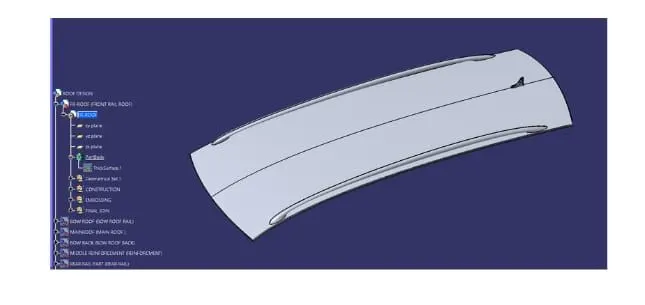
Import the file.File>open>browse file and select the given product (Product name.igs) as shown in the figure below:
Roof Design:
Given surface is A-class and we have to design Roof surface with the help of this A-class and the help of master section which is shown below:
There is two master section for the front end Rail roof and the next one is for the rear rail roof section:
Reinforcements and Design:
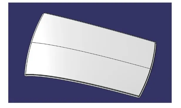
The Ditch Area is the extended portion of the main Roof concealed by other BIW panels. The rail supports of the roof are attached to the ditch Area using Spot welds. Since it is not a styling surface and remains concealed.
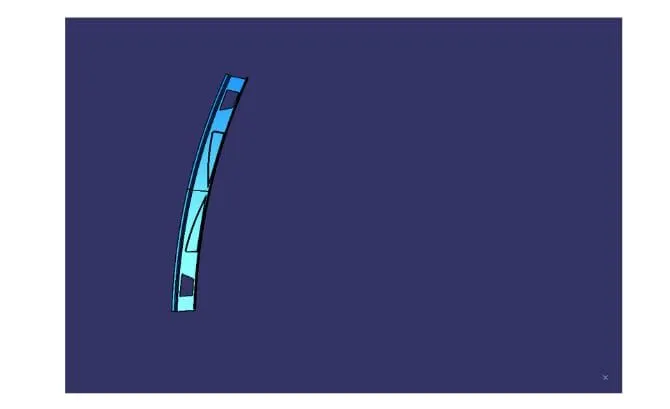
Front Roof Rail:
It is the support thst is joined the windshield glass. Body side outer and the inner panels. Its thickness is usually 0.75mm. The windshield end flanges are the extract offset of the roof surface. The bottom-most flangesis decided after taking into consideration the visibility criteria. Spot wweld is applied at the windshield end of the other end is joined with the roof using Mastics sealants which also contributes to increases strength.
Rear Roof Rail:
It is the support that is joined to the back door and body side outer and the inner panels. It is usually made from body side outer scrap and therefore the thickness of the rail is 0.75mm. Similar to the Front roof rail design. Wehave to take into consideration the rear headroom clearance and the rear visibility criteria while designing the rear roof railfrom the backdoor design and also taken into consideration od the required clearance. Spot welds are applied at the back door end of the rail and the other end is joined with the roof using Mastic sealants.
Bow Roof Rails:
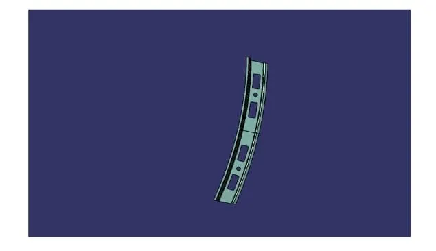
Similar to the other design, we have to take into consideration of the headroom clearance and the visibility criteria while designing the centre roof rail and Bow roof rail. Here spot weld is not applied for joining these rails of the roofs. Instead mastic sealants are used are introduced at both ends since centre Roofs are fully positioned under the styling surface of the roof. For increasing the strength of the rails, Embossing is done. To reduce the weight of the material used, Different stylinghas been followed with a thickness of 0.75mm.
Reinforcement centre Rail:
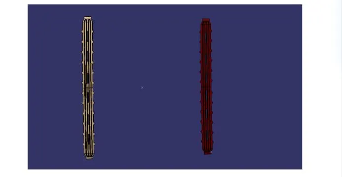
It is the main supporting rod for the roof. Their purpose is to provide an attachment point for crossbars and other devices designed to secure loads carried on the roof of the vehicle, It absorbs energy at the time of the crash . Its thickness is 1mm.
Analysis:
CURVATURE STUDY: It is done to justify the positioningof the Bow roofs. There are mainly two criteria to fulfil
- Heat distortion criteria
- Snow load criteria
Heat Distortio Formula:
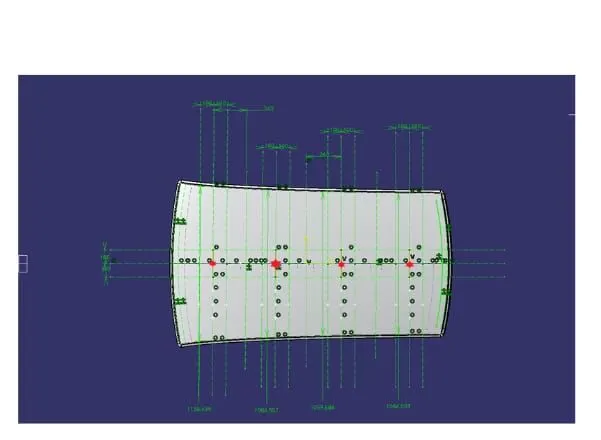
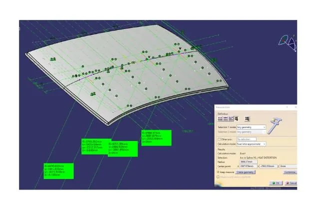
From the model we have the value shown in fig:
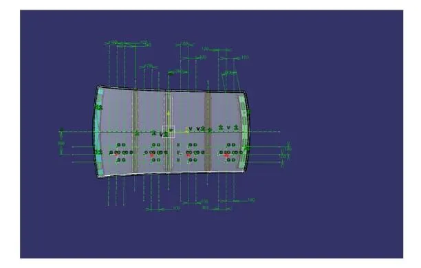
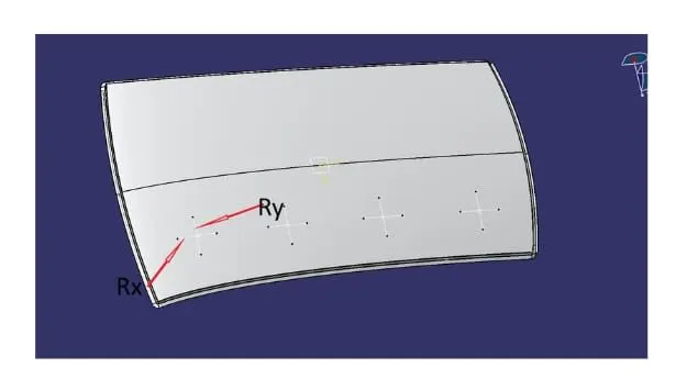
So after intersecting points on the line, we create 4 points and project them on the roof surface then join these points by using the spline option.
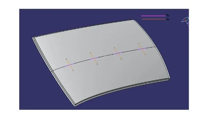
The Horizontal line is Rx and the Vertical line is our Ry .
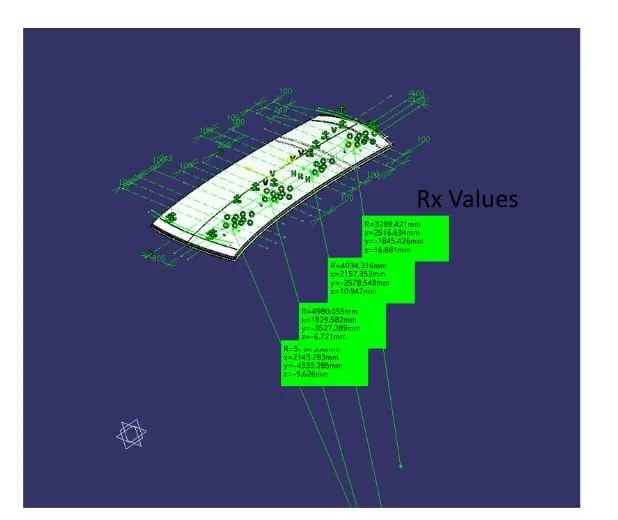
The Radius of curvature for the hood component along the x-axis is given below:
The Radius of curvature of the hood component along the Y-axis is below:
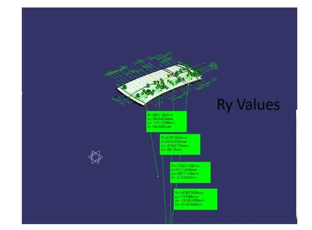
Calculations are done and tabulated in the tableas given below:
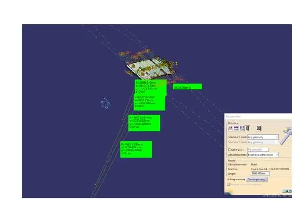
Snow Load Criteria:
After creating all the lines we intersect points and projest these points on the hood by using the spline curve option this will look like given below figure:
For the Geometrical Moment of inertia, we need a section at each rail, and shown in the figure below:
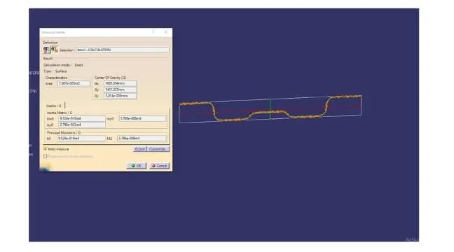
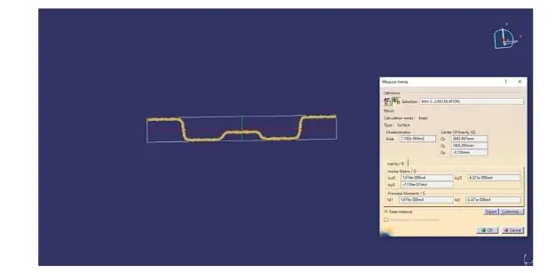
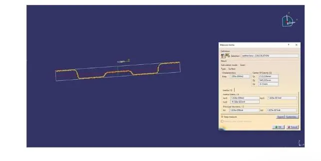
Calculationsare done and tabulated in the table as shown below:

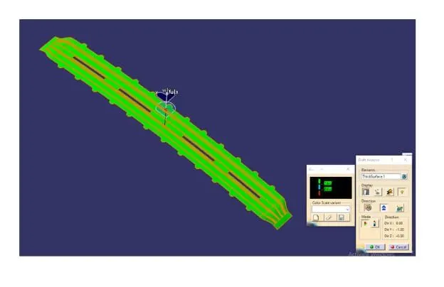
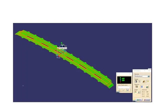
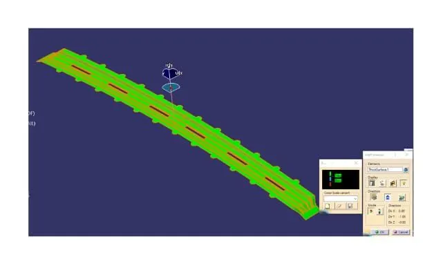
Draft Analysis:
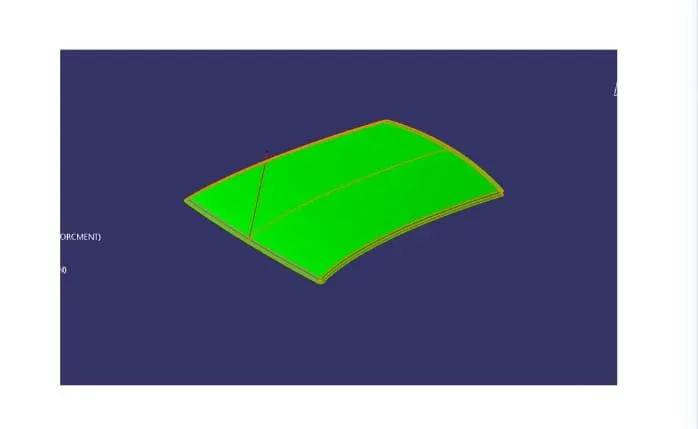
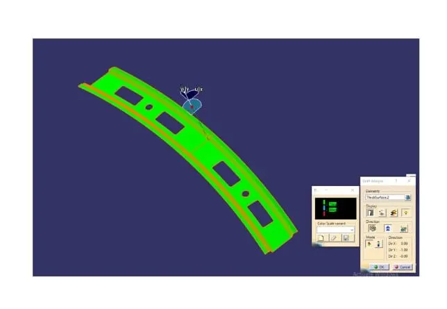
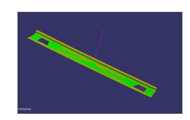
Draft Analysis is a method of checking the draft angle on various faces of a part in a particular direction. It should be more that 7 degrees. Draft Analyzing command which lets you know if your modelor design has a draft angle in a given tool direction.
If the part lines within the conditions it shows in green colous if not shown in blue or red colour.
The below figures show the draft analysis for analysis for Roof, Front Roof Rail, Rear Roof Rail,Bow Roofs and Reinforcement Center.
Results:
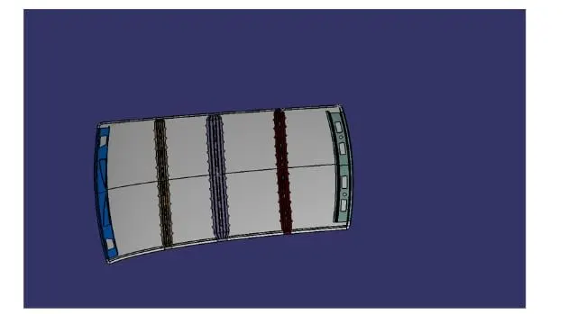
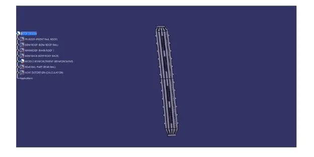
The Design of Roof, Front Roof Rail, Rear Roof Rail, Bow Ropofs, and Reinforcement roof center by following the Master section with the design parameter for the given class A surface is done and the final model is shown in the fig. below.