Wiring harness routing & packaging Rules Week 3 Challenge
Aim:
Electrically defined the given back shell and clamp with the help of geometry and create corrugated tubes and save in catalogue by the electrical wiring harness part workbench.
Introduction:
Wiring harness:
Systematic bound of electric wires and electric parts This process is doing in CAD for assembly and production. E.g.: wire, connecters, back shell etc
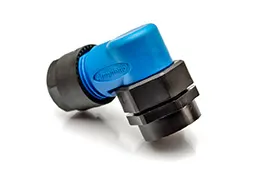
Back shell:
It connects the connecter and the wires which products the rear end of the connecter. It is made by plastics for electrical purpose.
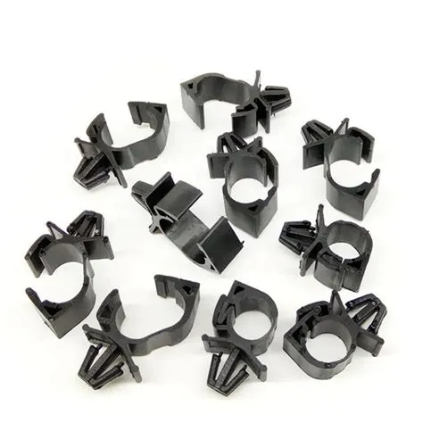
Clamp:
Which is hold and fixe the budles. Different types of clamps are available for multi purpose which made by plastics.
Corruglated tubes:
It is bellows shapes and flexible. It is using to product the wiring harness and give asthetic looks. It also made by platics.
Tools:
For electrically define we have to create some geometries and electrical part design tools.
Mechanical part work bench:
Point:
It indicates one location. This tool is used to create between two points in the centre of face.
Axis system:
It is fixed on a point and give X, Y, Z direction and plane in the location which is used to define and assemble the electrical parts.
Plane:
It is created with the help of point which is used to define clamps.
Electrical part work bench:
Define back shell:
This option is used to define the back shell. After this process CATIA will take the part as back shell.
Define back shell connection point:
This option is used to define the back shell point with the help representation, contact, coincident and orientation which are given by point, surface and axis system.
Define bundle connection point:
This option is used to define the bundle entry point of back shell with the help representation, which are given by point and face of surface.
Define cavity connection point:
This option is used to define the cavity connection point of connecter with the help representation, contact, coincident and orientation which are given by point, surface and axis system.
Define support part:
This option is used to define the support part with the help en
Electrical assembly:
Connect electrical device:
This option available in electrical assembly bench. This option is used to connect the two electrical devices. Arter defines the electrical device if we click the part, it automatically assembles with help of point, axis, face of surface from electrical define.
Disconnect electrical device:
This option is used to disconnect the two electrical devices from connected devices.
Methodology:
Designing:
Back shell:
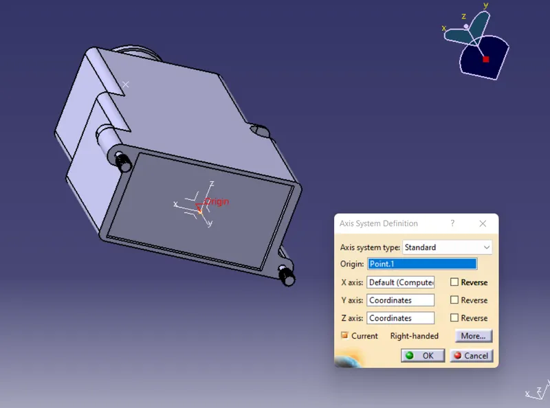
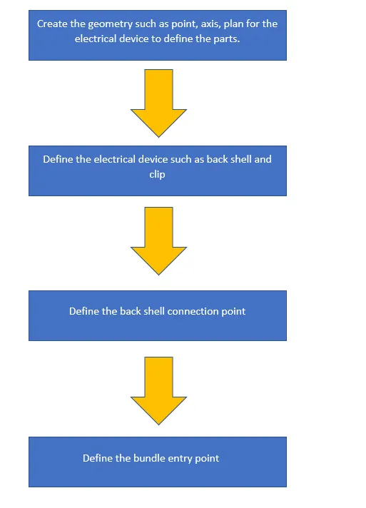
First create the geometry such as point, axis to define the electrical device.
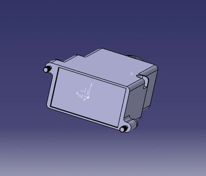
Then define the back shell.
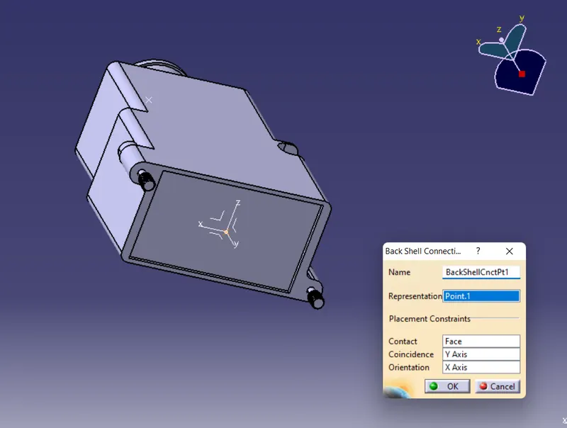
Then give back shell connection point.
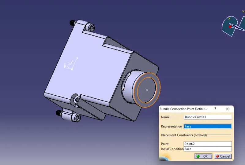
Finally, give buddle entry point and save in catalogue.
Clip:
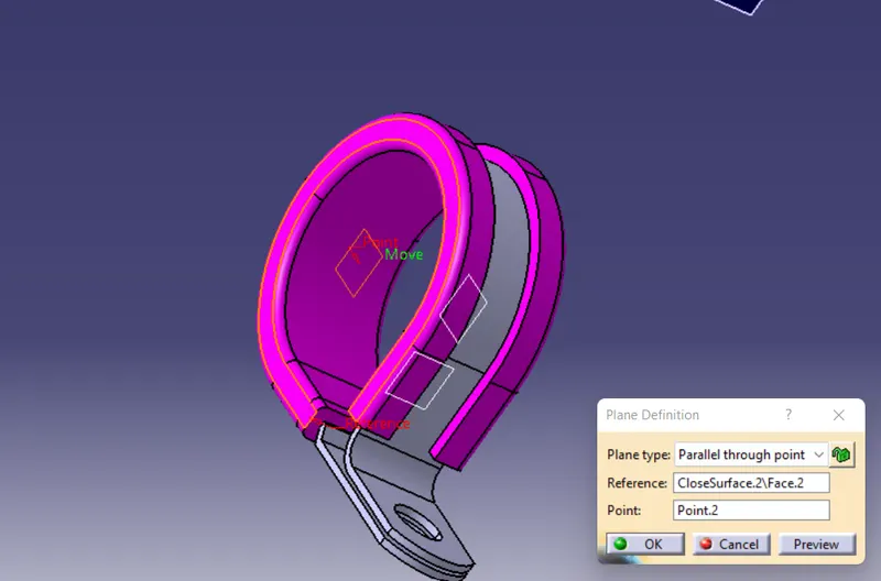
First create the points and planes for defining.
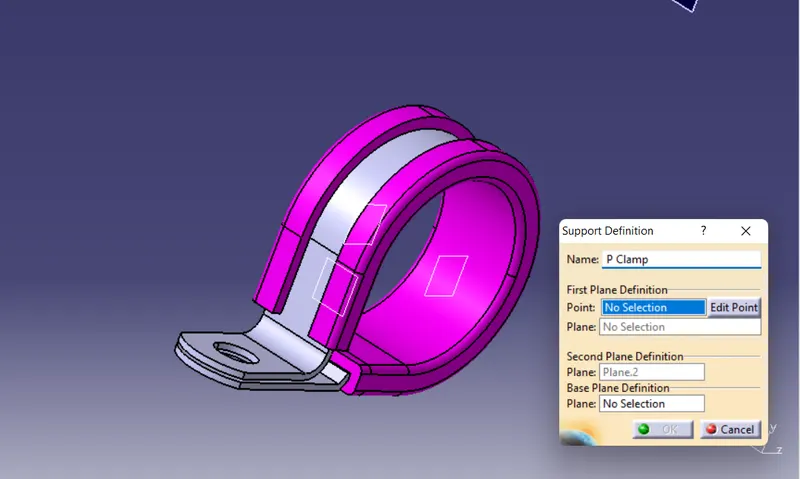
Then define the clip with help of plane and point.
Corrugated tubes:
We have to create the tubes and save in catalogue which is using for assembly.
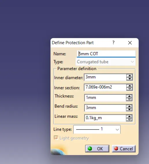
First give define production part and give dimension such as inner diameter, thickness and bend radius.
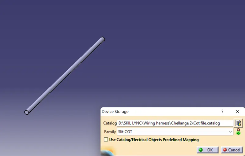
Finally, model was created and save in catalogue. Same method use to creat another four tubes.
Conclusion:
Given clip and back shell are successfully electrically defined and corrugated tubes are created and attached in catalogue by the help of CATIA.