MODELING OF SUNSEEKER YACHT BY SOLID WORK
MODELING OF SUNSEEKER YACHT BY SOLID WORK
AIM & OBJECTIVE
- Our ultimate aim is creating the modeling and getting the photo realistic rendering of Yacht by Solid work.
- This modeling is used to determine dimensions of parts and appearances for manufacturing.
- We have to create accurate model for giving manufacturing.
INTRODUCTION
YACHT
Yacht is one type of boat. It is sailing or power vessel used for pleasure, cruising, or racing. Generally applies to vessels with a cabin intended for overnight using. It is good attractive looking and private uses. Different types of yacht available depend on dimensions.
SOLID WORK
Solid work is one of the 3D CAD design software. It is used to develop mechatronics systems from beginning to end. Then it is used for design and building of mechanical, electrical and software elements. We are going to use this software to create the Yacht.
DESIGN METHODOLOGY
First draw the 2D sketches then change the 3D models sequently with the help of blue print. Mostly surface modeling is used in this modeling. Then give some appearance changes part or component or face level. This process is continued to create the different parts of yacht. Finally, assemble the all parts to create the yacht.
MODELING PARTS:
The yacht consists of the following parts,
- Propeller
- Rader
- Hull
- Garage door
- Front seat
- Middle seat
- Rear seat
- Superstructure
- Rader mast
STEP FOR DESIGNING:
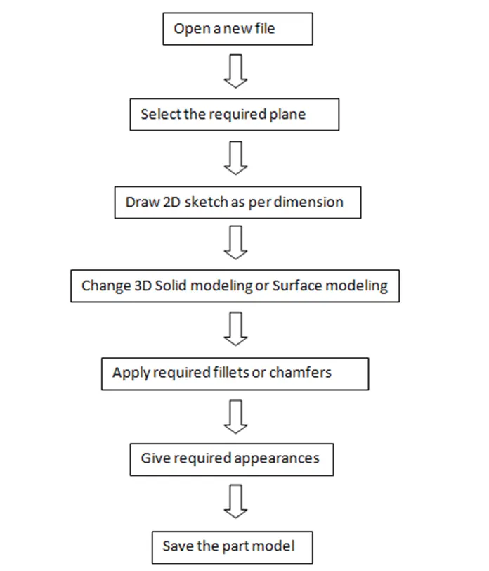
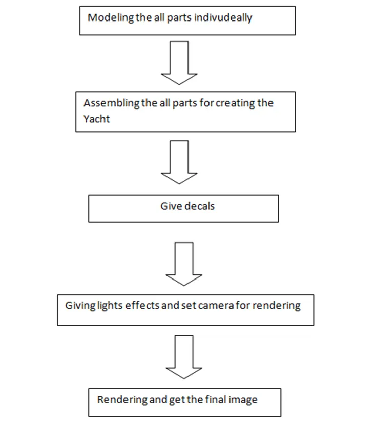
FLOW CHART OF PROCESSING:
TYPES OF TOOLS:
Sketch:
It is used to draw 2Dor 3D sketches with some dimension. Lot of tools are available in sketch.
Features
It is used to convert 3D model and give some feauture . Dimension is also given in this feature.
Surface
It is used to create zero thickness parts then we will give thickness. Prodects surface are created by this method.
Assembly:
Components are assemled y this tolls. Some type of mates are available. It is used to complete the assemblies.
Render:
Renter tools used for post working to give good look like set the environment, Camera, appearance.
1.SKETCH
- 2D sketch:
Select the plane and draw required shape with the help of dimension in 2D.
- 3D sketch:
It is directly drawn on parts in 3D along X, Y, Z AXIES.
- Different types of commands available in sketch tools such as line, circle, rectangle, spline etc.
2.FEATURES
Projection Curve
It gives 3D curve from two 2D curves where these are met in long surface extrusion which place it creates 3D curve.
Pattern:
This feature is used to create the many 2D or 3D parts in different path like liner, circular, etc.
Extrude bosses:
It is used to extrude the 2D sketch in one or two direction to form the 3D model.
Revolved boss:
Revolve the sketch with the help of lines or axis to form 3D model.
Extrude cut:
It is used to remove the particular portion in body with the help of sketch.
Swept boss:
It provides the solid body with the help of sketch. It gives by closed profile along an open and closed path.
Fillet:
It provides round edges at 2D and 3D both corners.
Chamfer:
It provides sloping edges at corners like fillet.
Shell:
It is used to create the hollow parts from solid parts.
Mirror:
This tools is used to create the another part like a part.
Dome:
It is used to create the mounded surface.
SURFACE MODELING:
Extruded surfaces:
It is used to extend the surface with the help of sketch.
Lofted surface:
It creates the surface between two or more profiles. We can give guide curve also.
Boundary surface:
It creates the surface with the help of boundaries. It gives good result than the loft tool.
Revolved surface:
It creates the surface by revolving with the help of line of axis.
Swept surface:
It provides surface by sweeping a closed profile along an open or closed path.
Filled surface:
It is used to fill the surface by sketch or boundaries.
Trim surface:
It is used to trim by intersecting. Two surface intersection line is used to trim the portion.
Knit surface:
It combines the two or more adjacent surface and surfaces are must merge with another surface. It is used to converts solid bodies also. If edges aren’t merged it won’t give solid body.
Offset surface:
It is used to create the offset surface which means copy of a surface with required gaps.
Split line:
It is used to create the line to separate the parts. It only separates the on surface for appearance.
ASSEMBLY COMMENTS:
Some comments are applied and merge the parts like coincident, concentric, distance relation.
RENDERING:
It provides quality reports from our modeling reports. It gives realistic images.
Appearance:
It is used to give different colors and materials to parts like plastics, metals etc. We can good appearance from this tool.
Scene:
It is used to give required background and environment image behind the parts.
Decals:
This feature is used to fix the stickers and etc.
Other renders tools:
Some tools like light effects, add camera, photo view 360 etc. used to get the different types of realistic image.
Only I have explained some important tools. Lots of tools available in solid works.Many tools are used in different places in solid works.
PART MODELLING:
BLUE PRINT:
Blue print is engineering or technical drawing is used a contact print process on light sensitive sheets. It is 2D picture. It is drawn in accurate dimension. Front, Back, Right side, left side view, Top and bottom view are separately drawn and fixed in plans for reference. Then, Its used to modeling the parts.
1. PROPELLER:
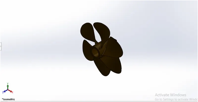
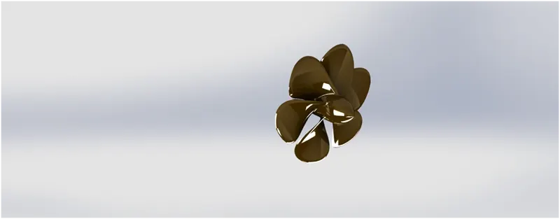
Generally, automatic boat and ships have many propellers. It is very important to move the boats or ships. It is function is move the ship forward y rotating and producing thrust on water.
COMMANDS:
SKETCH:
- Spline
- Circle
- Line
Features:
- Revolved boss
- Lofted boss
- Extruded cut
- Circular pattern
- Fillet
2.RADAR:
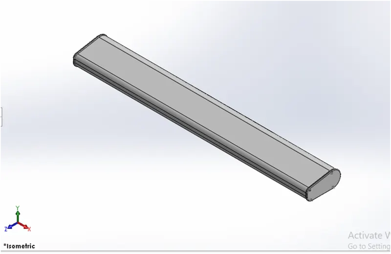
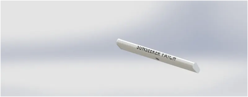
It is used to detect other ships and land obstacles. It is rotating and detects the targets. It is electronic instrument and fixed on the top of ship.
COMMANDS:
SKETCH:
- Line
- Text
- Circle
- Point
Features:
- Extruded boss
- Extruded cut
- Sketch pattern
- Fillet
- Mirror
- Split line
3.HULL:
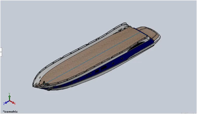
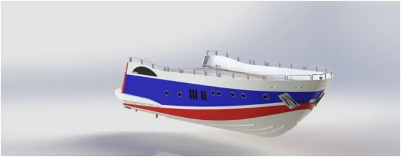
It is containing all parts of the ship. Top is open and partially covered with deck. It is floting on the sea. We can give different appearance on it like decals, paint etc. It is big part and base part of ship.Its size depends on ship size.
COMMANDS:
SKETCH:
- Line
- Spline
- Circle
- Rectangle
- Arc
- Slot
- 3D sketch
- Sketch plane
SURFACE:
- Extruded surface
- Revolved surface
- Lofted surface
- Surface Trim
- Surface Fill
- Surface Knit
- Delete Face
FEATURES:
- Project curve
- Chamfer
- Fillets
- Reference Plane
- Split
- Split line
- Extruded boss
- Extruded cut
- Mirror
4. GARAGE DOOR:
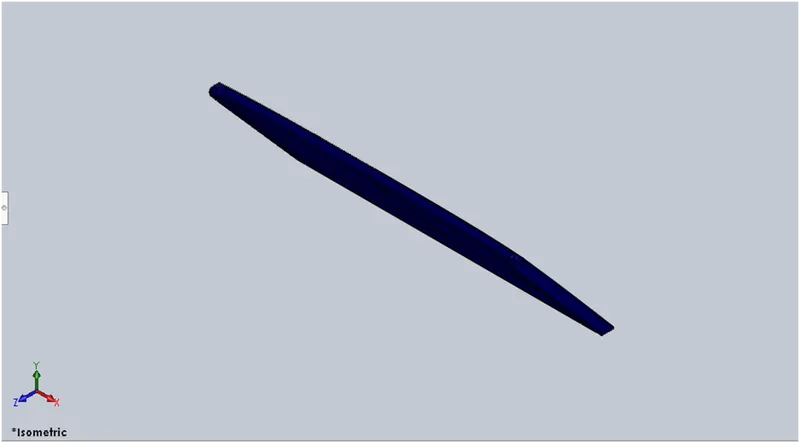
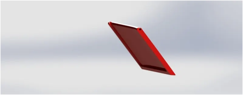
Garage door is a biggest door in ship. It is opened either manually or automatically. Vicheles are kept inside. Different types of material used to make this door like wood, metal or fiber glasses.
COMMANDS:
SKETCH:
- Line
- Spline
- Circle
- Text
FEATURES:
- Extruded cut
- Reference cut
- Fillet
- Shell
- Mirror
5. SUPERSTRUCTERE:
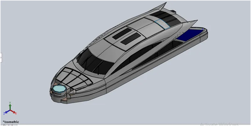
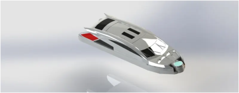
It is decked structure on the hull. It is closed part on the hull. It serves the purpose of the structure’s intended use.
COMMANDS:
SKETCH:
- Sketch picture
- 3D Sketch
- Line
- Spline
- Circle
- Rectangle
- Center Point Arc
SURFACE:
- Extruded Surface
- Swept Surface
- Ruled Surface
- Knit Surface
- Trim Surface
- Extend Surface
- Filled Surface
- Lofted Surface
- Revolved Surface
- Fillet
- Chamfer
FEATURES:
- Project cure
- Reference curve
- Convert entities
- Split
- Split line
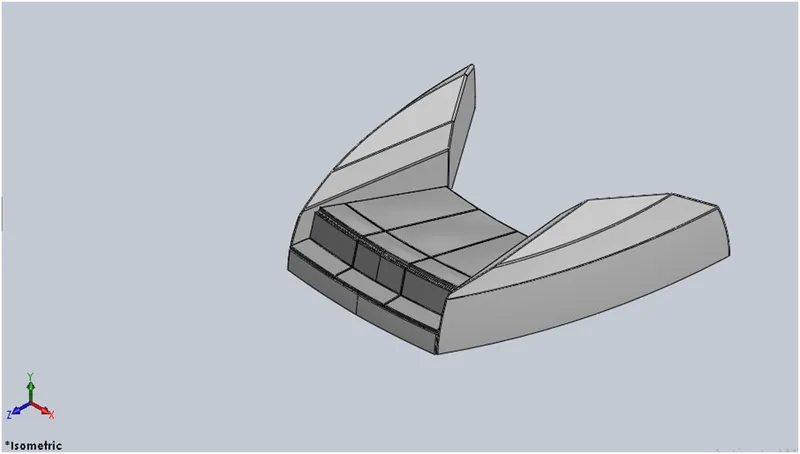
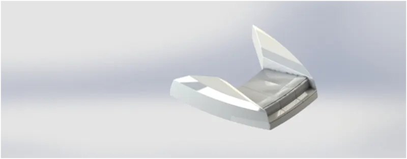
6. FRONT SEAT:
Two seats are connected to form front seat. It is placed front of superstructure. We sit on this seat more comfortable.
COMMANDS:
SKETCH:
- Sketch picture
- Line
- Spline
- CIRCLE
- Arc
SURFACE:
- Extruded Surface
- Lofted Surface
- Trim Surface
- Filled Surface
- Knit Surface
- Swept Surface
- Revolved Surface
FEATURES:
- Extruded Cut
- Revolved Boss
- Chamfer
- Fillet
- Mirror
- Dome
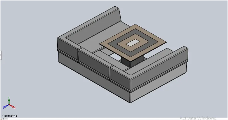
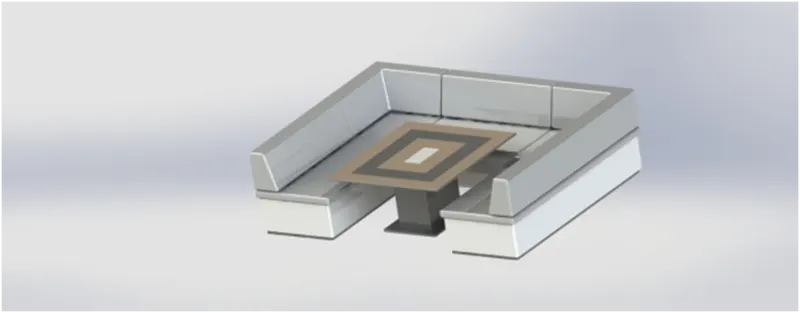
7. MIDDLE SEAT:
It is just behind the superstructure. It is with luxury tale for dinning. It also used for casual meeting.
COMMAND:
SKETCH:
- Sketch Picture
- Line
- Rectangle
FEATURES:
- Extruded Cut
- Chamfer
- Fillet
- Mirror
- Reference Plane
8. REAR SEAT:
It is in the end of the deck surface. It consists lockers and good looking. It is good for relaxation.
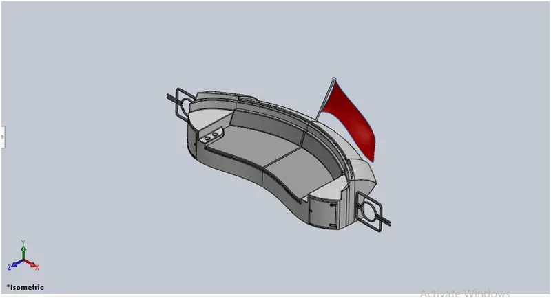
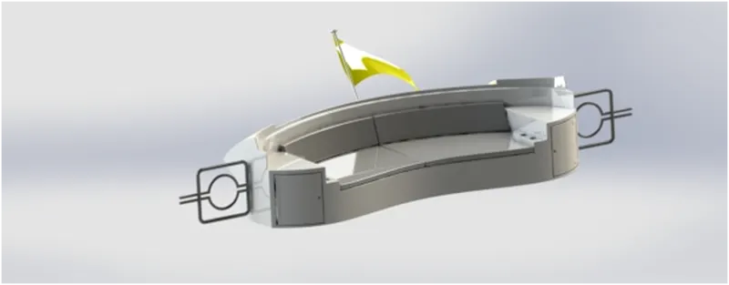
COMMAND:
SKETCH:
- Sketch picture
- Line
- Spline
- Circle
- Arcs
- Rectangle
SURFACE:
- Swept Surface
- Extruded surface
- Offset Surface
- Filled Surface
- Knit Surface
- Ruled Surface
- Lofted Surface
FEATURE:
- Reference Plane
- Extruded Boss
- Revolve Boss
- Fillet
- Mirror
9. RADAR MAST:
It is fixed on the super structure. Rader is fixed in this radar mast. It has radar, navigation light and Ships horn. It is very important and used to detect the ship.
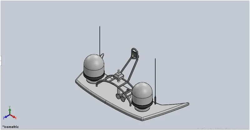
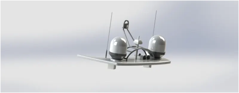
COMMAND:
SKETCH:
- Sketch Picture
- Line
- Spline
- Rectangle
- Arcs
FEATURE:
- Extruded Boss
- Revolved Boss
- Swept Boss
- Reference Plane
- Projected Curve
- Fillet
- Mirror
- Dome
- Shell
ASSEMBLY:
These individual parts are assembled here with the help of different mates like coincident, concentric and distance, angle mates.
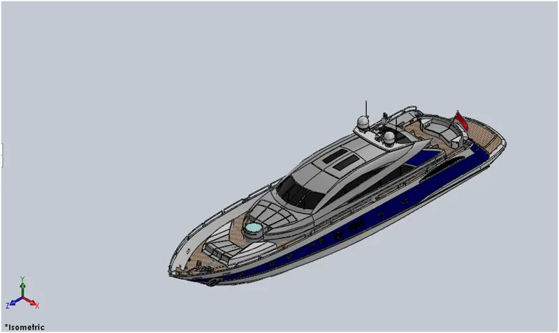
- First the hull is fixed in assembly page.
- Then rests of the parts are fixed on the hull with the help of coincident, concentric, distance mates.
RENDERING:
Final assembly yacht is rendered with some types of setup like light, camera etc. It is done by either photo 360 or photo visualization. By this feature we can get realistic images.
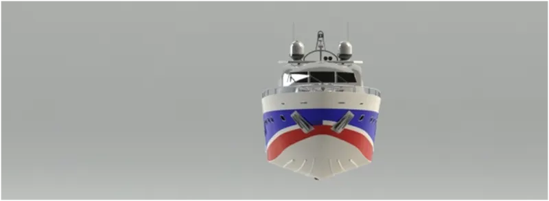
Front View
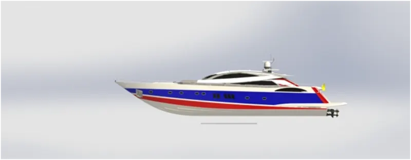
Right Side View
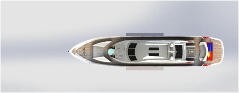
Top View
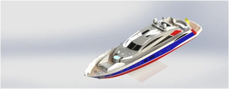
Isometric View
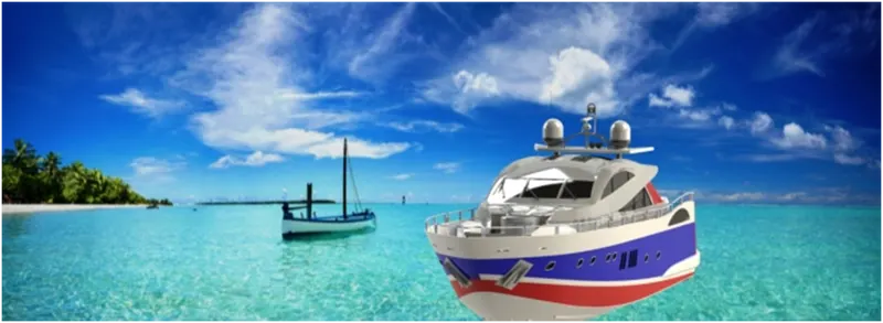
Camera Setup View 1
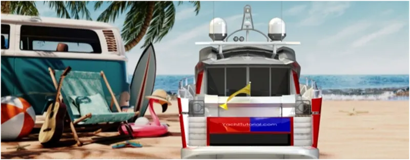
Camera Setup View 2
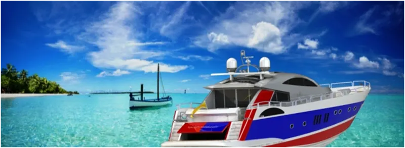
Camera setup View 3
CONCLUSION:
By this project we have learn different feature in solid work. We have got yacht with accurate dimensions and good appearance. Finally, Yacht has been done by solid work.