MODELING AND RENDERING OF AMERICN CHOPPER BY SOLID WORK
MODELING AND RENDERING OF AMERICN CHOPPER BY SOLID WORK
AIM & OBJECTIVE
- Our ultimate aim is creating the modeling and the photo realistic rendering of American chopper by using the solid work.
- It is used to determine the different parts dimension and appearance for manufacturing.
- We have to create best and accurate model to give to manufacturing.
INTRODUCTION
American chopper:
It is one of the bike modules. This is Long front ends with extended front forks with an increased rake angle, hard tail frames, broad rear fender, etc which are some of characteristic features of choppers. We are going to create the one of the chopper model is American chopper.
Solid works:
Solid works is one of the 3D CAD design software. It is used to develop mechatronics systems from beginning to end. It is then used for design and building of mechanical, electrical and software elements. We are going to use this software to create the American chopper.
DESIGN METHODOLOGY:
First draw the 2D sketches then change then 3 models step by step. Then give some appearance changes component level or parts level. This process is used to create the different parts for American chopper.
Modeling parts:
The chopper consists of the following parts,
- Transmission belt
- Kick stand
- Front fender
- Rear fender
- Chain
- Oil tank
- Pedal
- Front wheel
- Rear wheel
- Front Fork
- Chassis
- Engine
- Gas tank
Steps for designing:
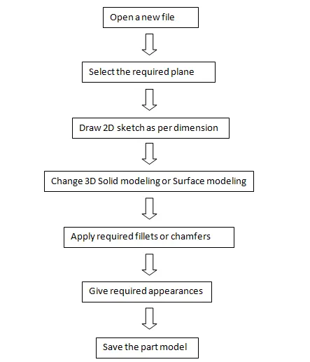
Flow chat of processing:
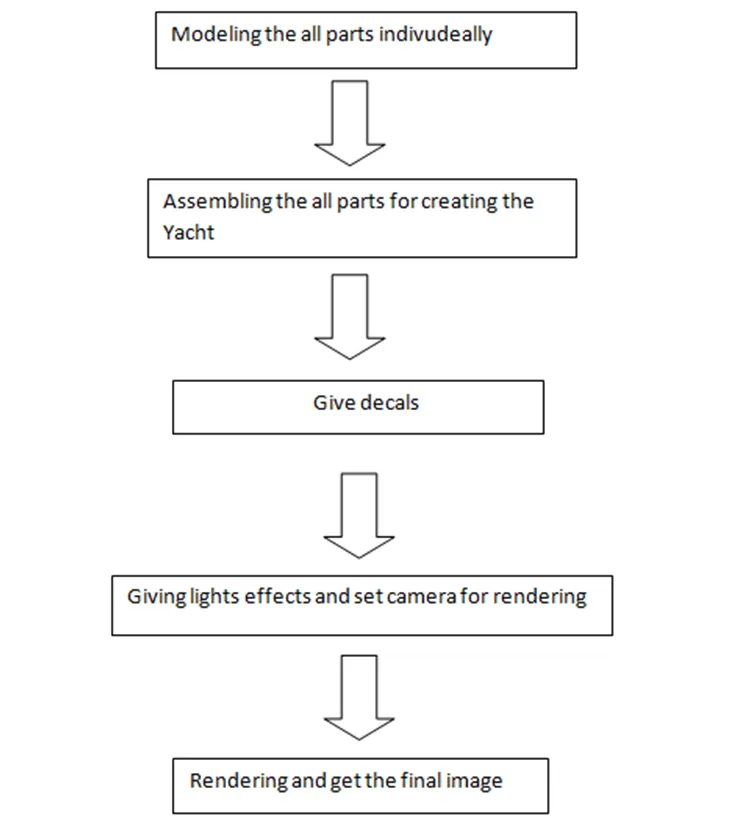
TOOLS:
Plane:
It has two dimensions length and width. 2D drawing is drawn on it.
Sketch:
Required dimension is used to draw on plane. It confirms dimension of parts. It is two types 2D and 3D. It depends on drawing.
Smart dimension:
It is used to give dimensions of parts. Dimension value give to the sketch to get the desired shape.
Convert entities:
It is used to get sketch easily from other or same plane parts 2D sketch with same dimension value.
Trim:
It is used to eliminate the unnecessary portion.
Offset:
It is used to create the 2D another parts like previous 2D parts.
Projection curve:
It gives 3D curve from two 2D curves where these are met in long surface extrusion which place it creates 3D curve.
Pattern:
This feature is used to create the many 2D or 3D parts in different path like liner, circular etc.
Extrude bosses/base:
It is used to extrude the 2D sketch in one or two direction to form then 3D model.
Revolved boss/base:
It is used to revolve the sketch with the help of lines or axis to form 3D model.
Extrude cut:
It is used to remove the particular position in body with the help of 2D sketch.
Swept boss/base:
It is provide the solid body with the help of 2D sketch. It gives y closed profile along an open and closed path.
Fillet:
It provides round edges at 2D and 3D both corners.
Chamfer:
It provides sloping edges at corners like fillet.
Shell:
It is used to create the hollow parts from solid parts with required wall thickness.
Appearance:
It is used to give different colors and materials like plastics, metals. We can get the different looks from this tool.
Decals:
It is used to fix printed stickers and etc.
Renders:
It provides quality reports from our modeling reports. It gives realistic images.
Only I have explained some important tools. Lots of tools are available in solid works. Many tools are used in different places in solid works.
Part modeling:
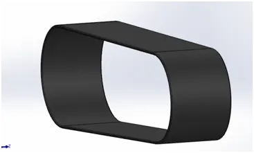
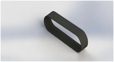
1. Transmission Belt:
It is rotated between the shafts. It is cheapest utility for energy transmission. It runs smoothly with little noise. It is very good economical product for energy transmission.
Modeling:
- I drew on front plane with using line and 3point arc with desired dimension and constrain to make fully defined sketch.
- Then offset tool is used to create another sketch like previous sketch in inward side.
- Extrude boss tool is used to extrude the 2D sketch with desired width.
- Finally give matte rubber appearance to part.
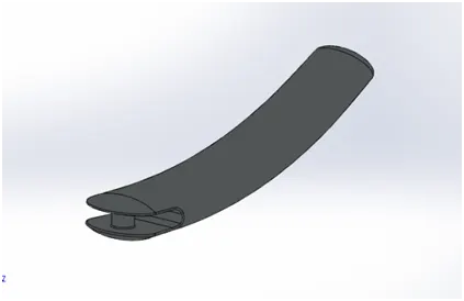
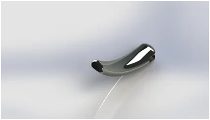
2. Kick stand:
It moves up and down. It is attached with chassis. It keeps the like in upright position. Chopper is in stationary.
Modeling:
- First I drew ellipse on front plane and spline on right plane modify desired dimension.
- Create another plane on end of spline. Draw ellipse on this plane.
- Loft feature is used to create the 3D model between with the help of spline..
- Applied dome and cut extrude tool is used to cut desired portion in broad dome side. Then drew and extruded circular shape between cut extrude inside faces.
- Apply desired fillets on edges.
- Finally apply chrome plate appearance to part.
3. Front Fender:
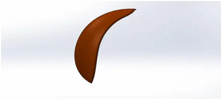
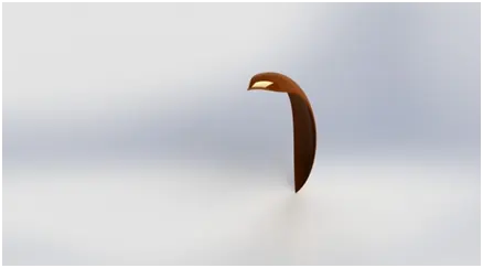
It prevents bike from liquids, dirt and mud from moving wheels. It enhances the appearances of chopper.
Modeling:
- Drew 3point arc then offset the arc in inside and merge with line.
- Revolve boss feature is used to revolve desired shape with the help of sketched horizontal line or temporary axis.
- Create the sketch on top plane and another sketch on front plane then split tool is used to eliminate the unwanted portion.
- Then apply required fillets at corners.
- Finally applied metallic paint siena appearance to part.
4. Rear Fender:
It is used like front fender for front wheel.
Modeling:
- Same front fender process is used to create this model.
- Some changes are in sketches like 3poin arc.
- Same metallic paint siena appearance to this part.
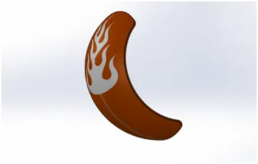
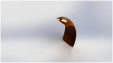
5. Oil Tank:
Oil is stored in it for lubrication and cooling.
Modeling:
- I sketched on front plane and top plane and Extrude boss feature is used to extrude the 2D sketches.
- Then combine feature is used to keep the common of two extruded portions.
- Then this combined part change hollow from solid part with the help of shell tool.
- Fillet is applied for smooth edges.
- Finally applied metallic paint siena color appearance to oil tank outside portion.
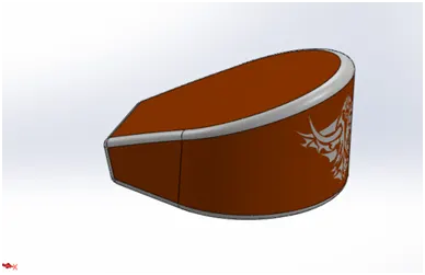
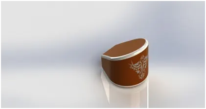
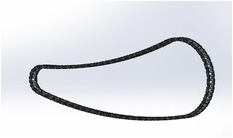
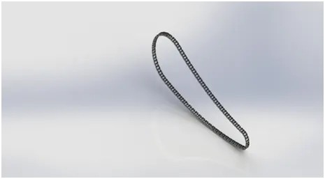
6. Chain:
It is used for energy transmission to the rear wheel from engine. It is combined engine and rear wheel
Modeling:
- I sketched chain path on front plane and sketched inner and outer plate separately save in file for using later.
- Plates are fixed in path then extruded separately (pin, inner and outer plate).
- Curve Driven pattern is used to create many pin, inner and outer plate in full chain path. One side chain portion created.
- All inner and outer plates are mirrored with the help of mirror feature. Full chain is created successfully.
- Finally applied chrome plate appearance to the chain.
7. Pedal:
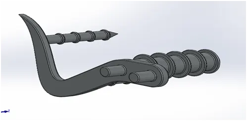
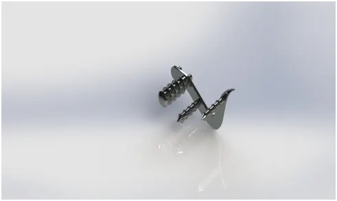
This is used multi purposes. It used for rear break, gear changes and foot rest.
Modeling:
- First drew required 2D sketches with the help of line, spline, 3 point.
- Various feature used to create the model like Extrude Boss, Revolve Boss, Dome feature.
- Fillet and chamfer are applied. Finally linear pattern is applied to finish the model.
- Same chrome plate appearance is applied to the model.
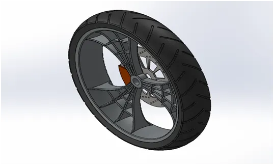
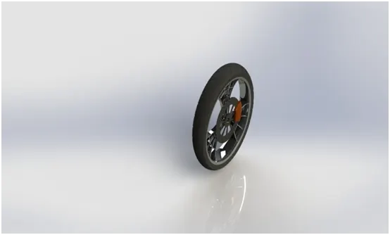
8. Front Wheel:
Wheel is used move the vehicle forward and absorbs some shocks also.
Modeling:
Front wheel contains Rim, Rotor, Break Caliper and Tire.
Rim:
- Sketch and revolve to create ring.
- Then extruded bosses used to hub.
- Extrude Boss, Cut extruder, Revolve cut and circular pattern, fillet to finish the model.
- Finally combine tool is used to combine the all parts.
Rorer:
- Sketch and Extrude bosses used to create the disc.
- Cut extrude and Circular pattern used to eliminate the extra portion and finish the model.
Caliper:
- 2D sketch create on rotor.
- Then Extrude boss used to extrude the sketch.
- Finally Chamfer and fillet applied on edges.
Tire:
- Convert Entities used create the fully defined sketches.
- Revolve Bosses feature is used to create the tire portion.
- Cut extruder is used to form treads.
Applied appearance individually rim and rotor are chrome plate. Caliper is metallic paint siena. Tire is metta rubber material.
9. Rear Wheel:
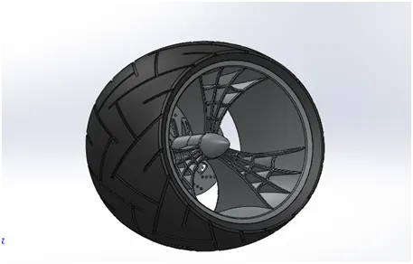
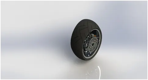
It is used like front wheel. All break, accelerator controlled here.
Modeling:
- Same rear wheel way is used to create the multi parts like Rim, Rotor, Caliper and Tire. It is having only one extra body which is sprocket.
- Sketched and Extrude boss to create disc.
- Extrude cut is used to create tooth profile of sprocket.
- Circular pattern is used to finish the tooth the sprocket.
- Apply appearance individually. Sprocket is chrome plate.
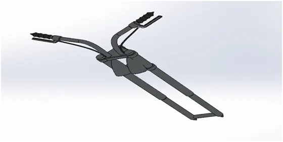
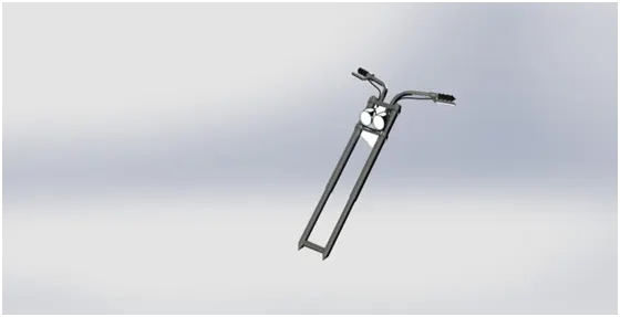
10. Front Fork:
Front wheel and front fender are mounded in it. Otherwise head light, indicator, shock absorber, clutch, handle, etc also mounded in it. It steer the vehicle when turning the bike.
Modeling:
- Sketch and revolve boss, extrude boss, Extrude Cut, projected curve and sweep boss to create the rod and handle bar.
- Then Revolved cut and move body are used to make head light.
- Mirror feature is used to finish the model.
- Applied appearance individually to the parts like handle bar, light, other body.
11.Chassis:
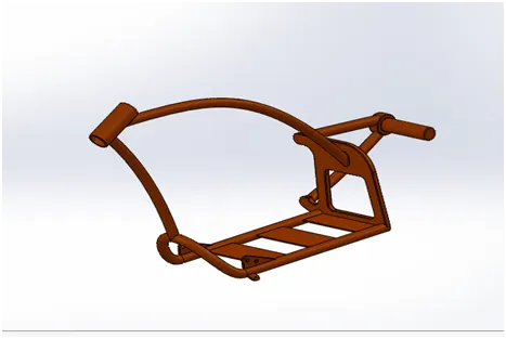
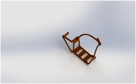
It is the skeleton of chopper. All parts are fixed in it which engine, Fuel tank, rear fender and rear wheel etc.
Modeling:
- Blue print is used to sketch and some features like projected curve, Sweep boss, Extrude Boss, Extrude cut, Revolve Boss, Split, Combine and Fillet are used to complete the model.
- Finally metallic paint siena applied to finish the model.
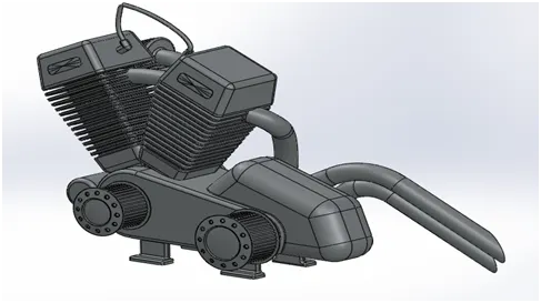
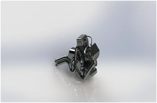
12.Engine:
Engine gives energy to vehicle. It is energy house of vehicle.
Modeling:
- Blue print is used to sketch and Extrude boss, Revolve boss, Cut extrude, Dome, Chamfer, Circular & Linear Pattern, Split and Combine feature are used to create the transmission box and cylinder.
- Projected curve and composite curve to make exhaust pip.
- Sweep boss to create the spark plug and finish the model.
- Applied appearance to engine’s parts.
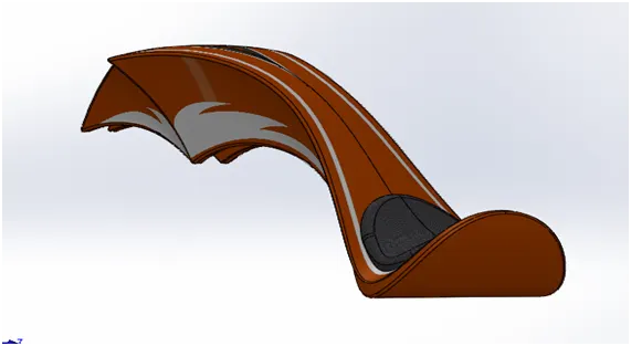
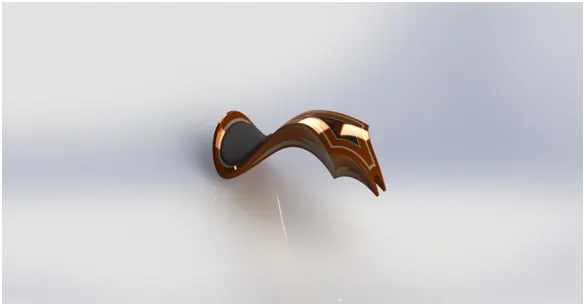
13.Gas Tank:
Fuel or gas is stored here to give to engine.
Modeling:
- Sketch and sweep surface, Trim surface, Projected Curve, Surface Loft, Boundary surface, Surface Knit to make surface body of gas tank.
- Then Sweep cut, Shell and Fillet apply to finish the model.
- Applied metallic paint siena appearance to the gas tank.
Assembly:
- Assembled the chopper first chassis followed by engine, Paddle, Kick stand, transmission belt, Oil tank, Rear Wheel, Chain, Gas tank, Front fork, Front wheel and Front fender.
- Some mates applied such as Coincide, Concentric, Parallel, Distance, Tangent, and advanced mates such as Width and Limit Angle applied to finish the assembly.
- Mirror feature is used to mirror the pedal on other side.
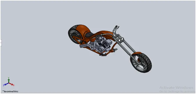
Decals:
Decals applied on gas tank, Oil tank and Rear fender which is applied for attractive look.
VIEWS:
Lights setup:
- We can customize the environment and vehicle by Solid Works.
- We can add many lights setups such as Spot, Point, Directional, Sun light.
- Also we can add different environment like HDR which give reflection on reflecting surface.
Camera set up:
- We can get multiple camera views in solid works.
- We can fix the camera in different position around the model to get the images.
Rendering:
- We can render the model two types.
- Photo views 360
- Solid works Visualize
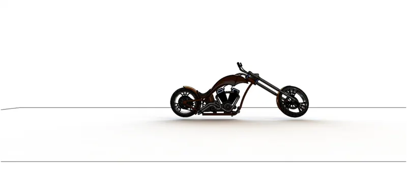
Front view
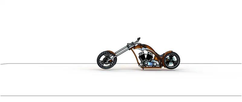
Back view
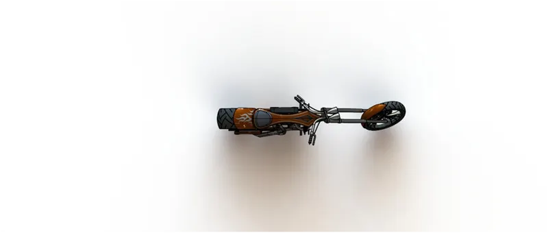
Top view
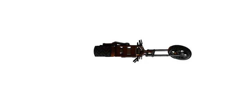
Bottom view
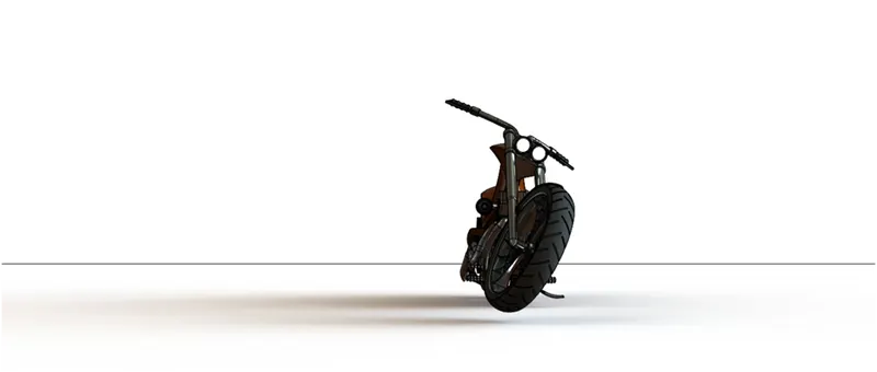
Right side view
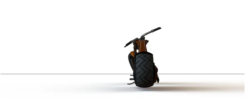
Left side view
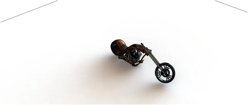
Isometric view
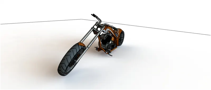
Camera setup view 1
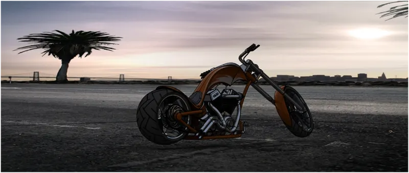
Camera setup view 2
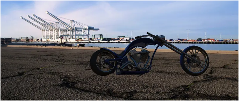
Camera setup view 3
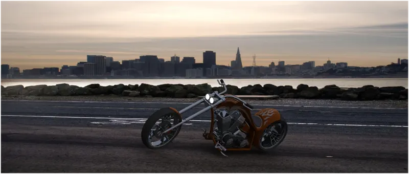
Camera setup view 4
CONCLUSION:
Different features are used to model the parts, assemble, give different light setup and rendering of the American Chopper. Finally, American chopper is successfully done by Solid works.