Wiring harness routing & packaging Rules Week 3 Challenge
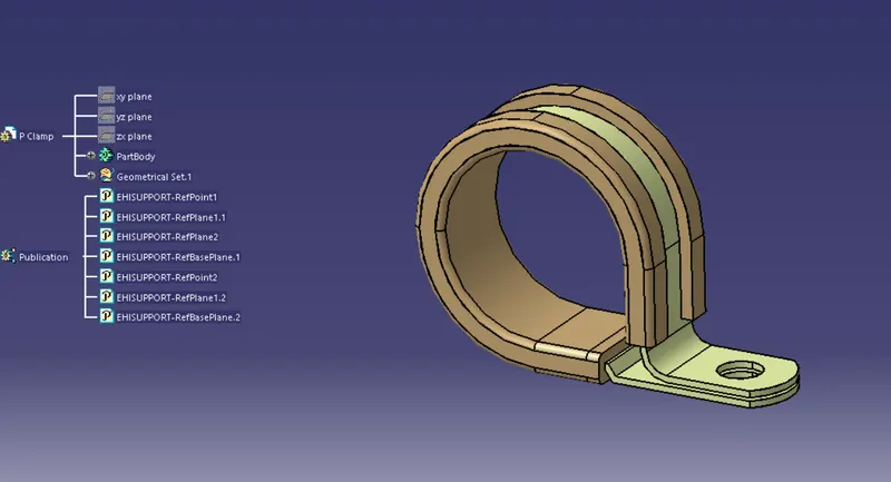
1. P CLAMP
Open the CAD file in Catia in part design workbench
Lets define the geometric parameters
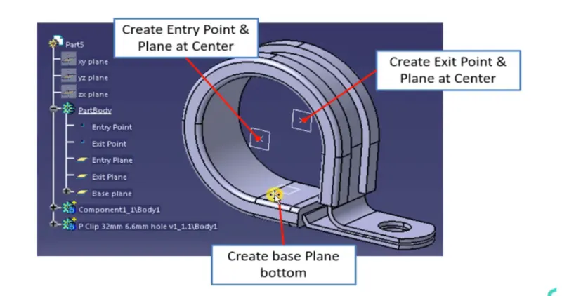
- Create entry point and plane
- create exit point and plane
- create a base plane
- Switch to electric part design
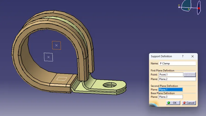
- Click on define support part ,select the part, select the entry point,entry plane, exit plane, base plane
- Repeat this one more since we have two entry path and 2 exit path
2. BACKSHELL
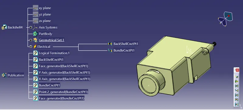
- Open the CAD file in part design workbench
- Now lets define the geometric parameters
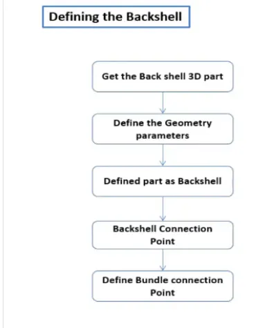
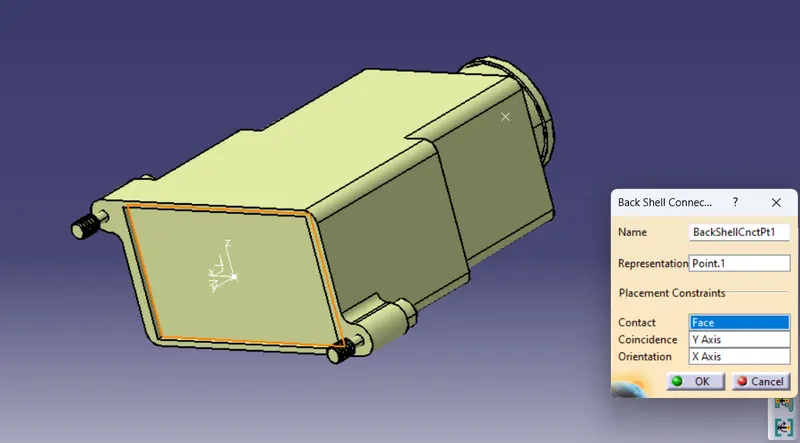
- Create Back shell connection point.
- Create axis system for back shell connection point.
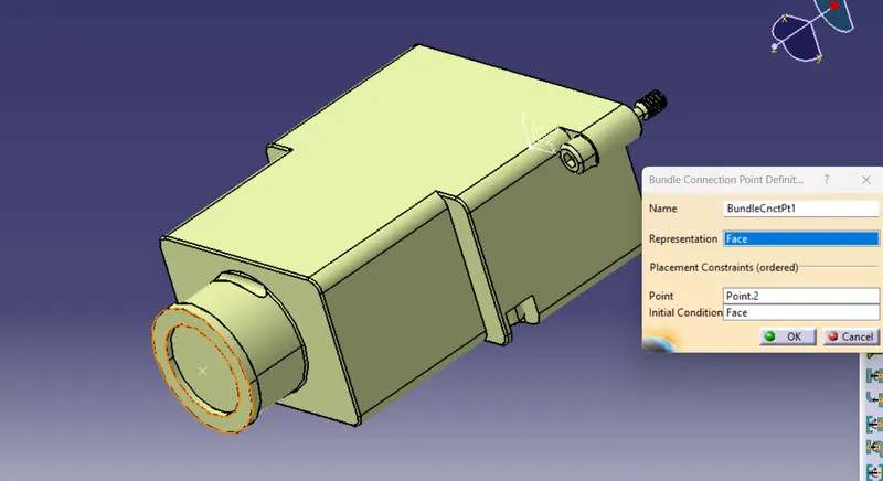
- Create bundle connection point.
- switch to Electrical part design.
- Define part electricaly as back shell.
- Then define Back shell connection point.
- Define bundle connection point.
3. CORRUGATED TUBES
- Open a new part file in Electrical Design workbench
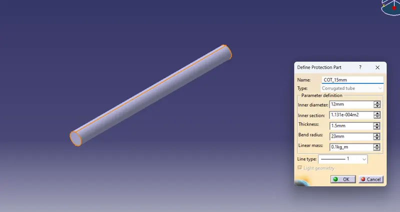
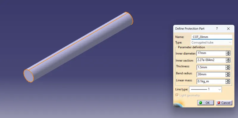
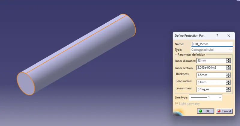
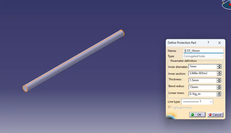
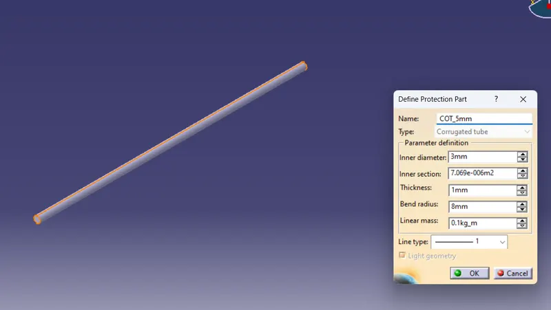
- Click on define protection part
- Then click on the file name and define the dimensions like inner diameter, thickness and bend radius( 1.5 x External diameter)
- We should add the created part in to the respected catalogue for that we should create a catalogue first
CATALOGUE CREATION
- Select catalogue document from NEW
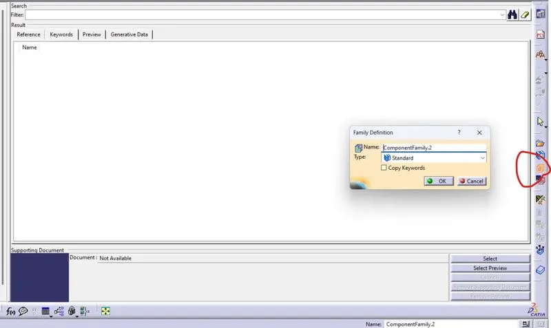
- Cllick on add family then Name it like COT_tube _catalogue and select CONDUIT as type and save it
After creation of catalogue
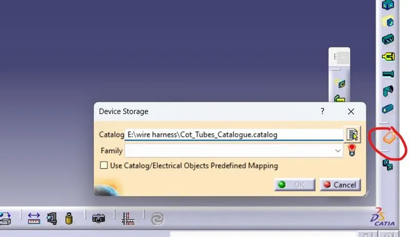
Finally click on store device and the created part file in to the catalogue and select the family
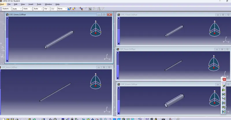
Below figure show how to family definition involved in creating catalogue
15mm COT
20mm COT
35mm COT
10mm COT
5mm COT
We can store the created part in to the catlogue using device storage as shown below