Wiring harness routing & packaging Rules Week 3 Challenge
Wiring harness routing & packaging Rules
Objective-
1- Download the following cad data & define it as Electrical support using the Electrical Part Design Workbench. Define all the necessary properties.
2- Download the following Back shell cad data & define it as an Electrical back shell using Electrical Part Design Workbench. Define all the necessary properties.
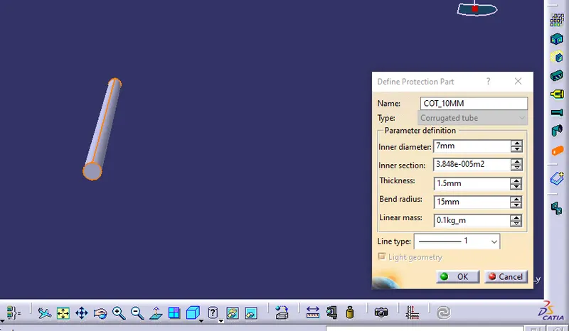
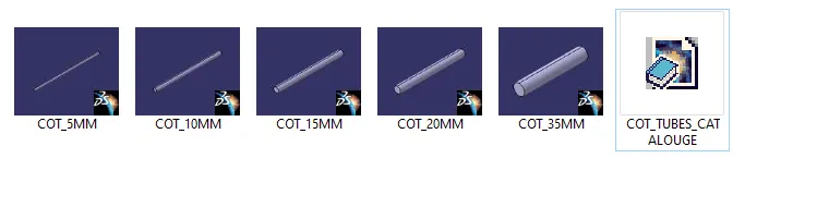
3- Create the Following Corrugated tubes & add them to the Catalogue under the “Slit COT” family.
|
Name |
ID (mm) |
OD (mm) |
Thickness (mm) |
|
15mm COT |
12 |
15 |
1.5 |
|
20mm COT |
17 |
20 |
1.5 |
|
35mm COT |
32 |
35 |
1.5 |
|
10mm COT |
7 |
10 |
1.5 |
|
5mm COT |
3 |
5 |
1 |
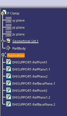
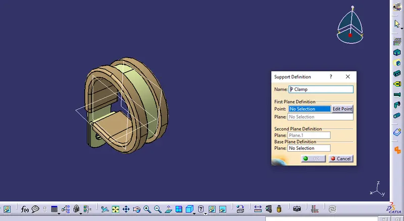
- P CLAMP:
- Open the cad file in Catia v5.
- open the mechanical part design workbench.
- define the planes and points.
- switch to the electrical part workbench
- define the part as support.
- define the two-entry point and two-exit points.
- BACK SHELL:
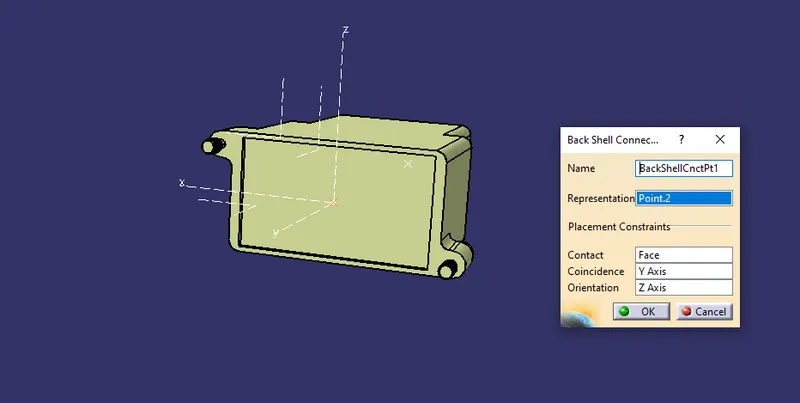
- Back shell connection point:
- To create such a Backshell connection point, follow the below steps:
- Switch to part design,
- Create a midpoint
- Create Axis System with respect to the point which we have created and define the axis direction as shown below
- Switch to 'Electric Part Design'
- Define the part as backshell.
- Define the backshell connection point.
-
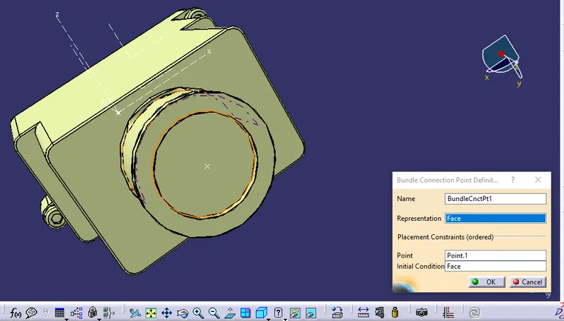
- Bundle connection point:
- The bundle connection point is used to specify the position and the direction of the bundle segment connected to the connector or the equipment.
- Switch to part design,
- Create a midpoint on the contact face which will be normal to wire bundle insertion.
- Switch to 'Electric Part Design'
- Since we had already defined the component as a Backshell.
- so, Define Bundle connection point
- CORRUGATED TUBES:
- create the new part file.
- switch to electrical part design
- define the protection part on the basis of given data.