Wiring harness routing & packaging Rules Week 3 Challenge
WIRING HARNESS ROUTING AND PACKAGING
AIM:
1. To define the given PCLAMP as a Electrical support using electrical part design workbench along with all the necessary properties of it.
2. To define the given mechanical Backshell as an electrical backshell by using electric part design workbench and all the necessary properties of it.
3. To define following corrugated tubes and add them in catalouge uner "Slit COT" Family
| Name | ID | OD | Thicknesss |
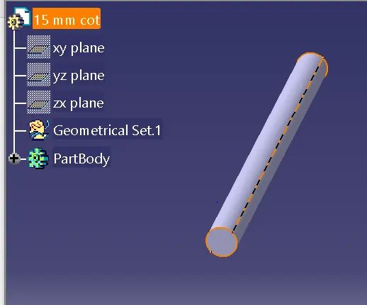
| 15mm COT | 12 | 15 | 1.5 |
| 20mm COT | 17 | 20 | 1.5 |
| 35mm COT | 32 | 35 | 1.5 |
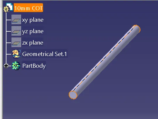
| 10mm COT | 7 | 10 | 1.5 |
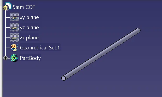
| 05mm COT | 5 | 5 | 1 |
Introduction:
P Clamp
P-clamps lock cables and hoses in place and help ensure that machinery, vehicles and equipment keep running. They bracket wires, cables or hoses together mechanically and are fastened securely to an anchor point – usually with a screw or a bolt.
There are two options to use, you can either place the clamps around the cable or hose and then mount it all or you can pre mount the clamps. And then close them around your cable.
Back shell
Backshells are plastic molded parts used at wire entry side of connectors either for protection or to improve asthetic/apperarance of harness. It will be attached to the back of connectors often designed to guide the wires and cables that are terminated at the connector. The backshells are often mated with strain relief components, environmental seals, the shielding
Corruugated tubes
It's on of the types of protective coverings are used to protect the wiring harness. The cylindrical first regions of the corrugated tube are positioned adjacent to connectors at the ends of the wire harness. This feature allows electrical wires of the harness to be uniformly distributed therein and prevents them from being twisted when the electrical wires are inserted into cavities of the connectors.
1.Definition of P clamp as Electrical Support
Steps:
| Get the 3D model of the P clamp |
| Define geometrical parameters |
| Define part as support |
| Define entry point and plane |
| Define base and exit plane |
Geometrical Parameters definiton:
The important parameters Entry point and plane, Base plane and Exit plane are required to define as electrical part.
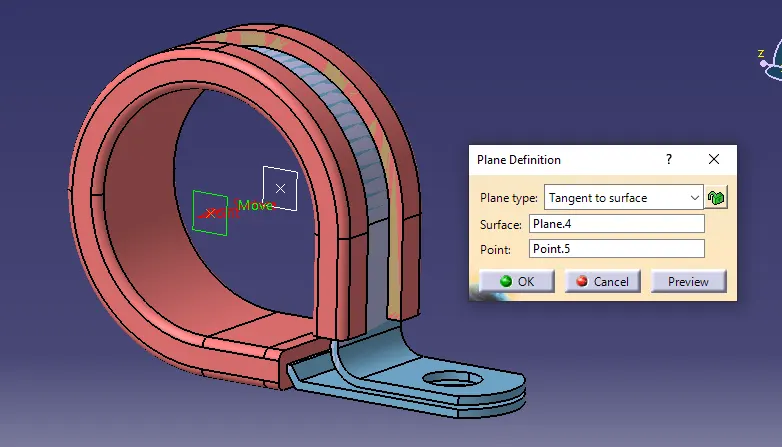
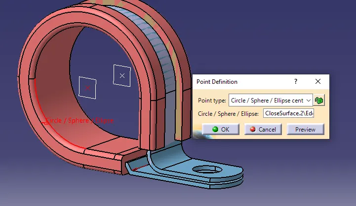
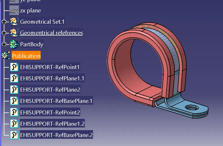
clip has two entry points and two exit points. the following image shows creation of planes at entry, exit and base of the clip using point and plane definition commands.
Part Defintion:
The given mechanical part will be converted or defined as an electrical support In the electrical design part workbench by using the geometrical parameters.
The following image shows about support definition of part,
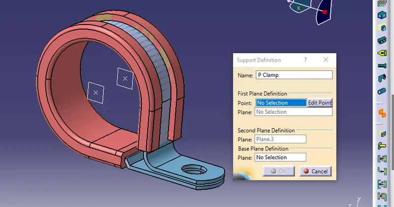
Here, two entry and exit points are given with respective palnes.
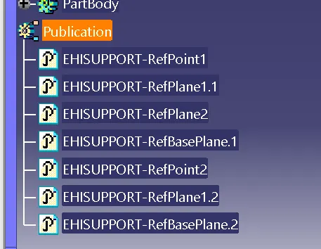
The above image shows all the properties of p clamp as defined as electrical support.
2. Back shell definition,
After completion of downloading the 3D model of the backsjell form the internet. Give the axis system in the same orientaion of the connector connection point.
Geomentrical parameters defenition,
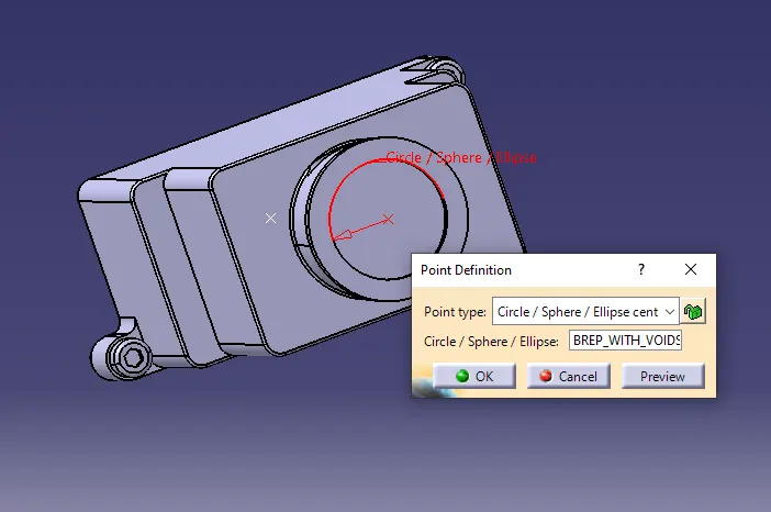
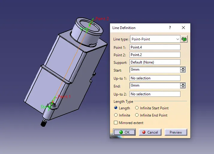
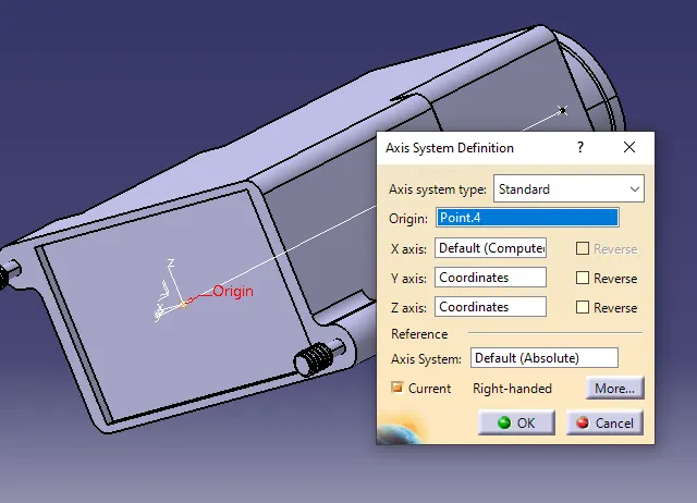
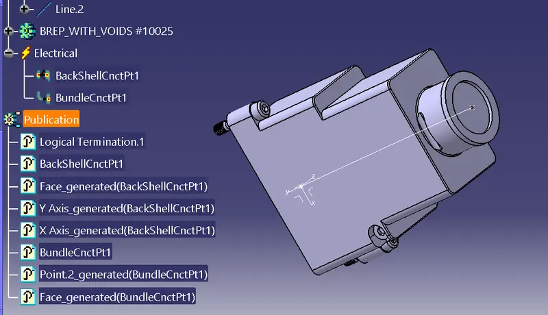
The above image shows about creation of point, centre line and axis of the product.
Switch to electrical part design workbench. select the define backshell command and select the component. In the extra length option the required extra length can be provided.
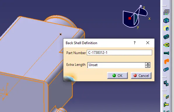
Definition of bundle entry connection point from connector in backshell.
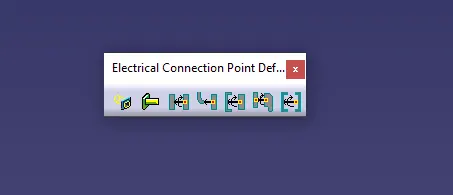
this is the toolbar in electrical part design to define connecting points.
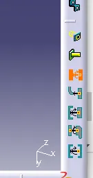
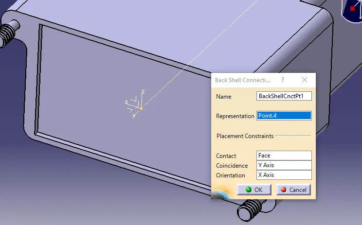
Here, the centre point will be selected as representation,
normal face is the contact face,
coincidence is the Y axis,
and x axis is the Orientation.
Bundle Connection point
This is the point where bundle segment or wire point end when get routed to a connector. This point is known as Bundle Connection Point. At the time of defining bundle connection point, the number of terminals and a face is also provided as an input data.
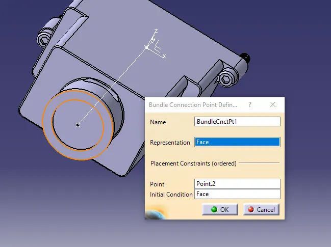
3. Corrugated tubes creation:
| Create covering 3D part |
| Create catalogue for covering |
| Add new part in catalogue |
| Apply covering on hardness bundles from catalouge |
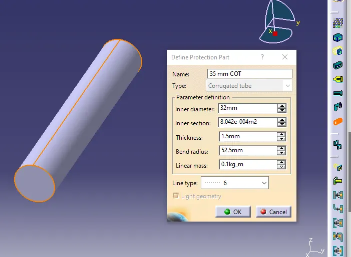
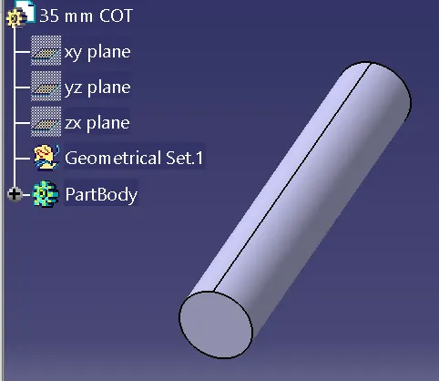
35mm COT,
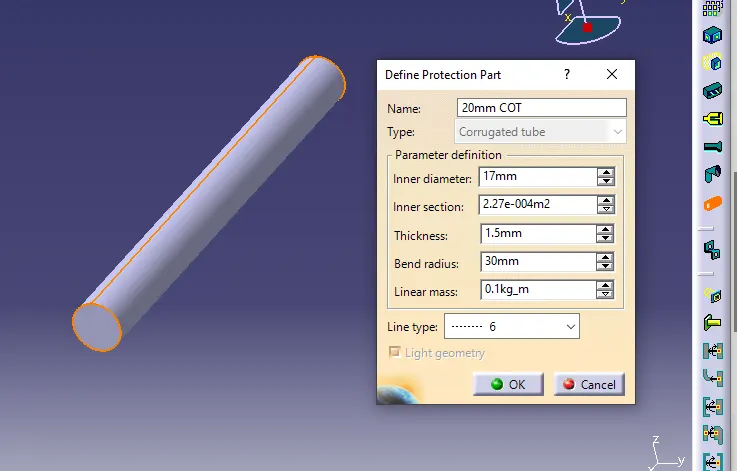
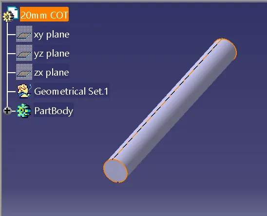
20mm COT,
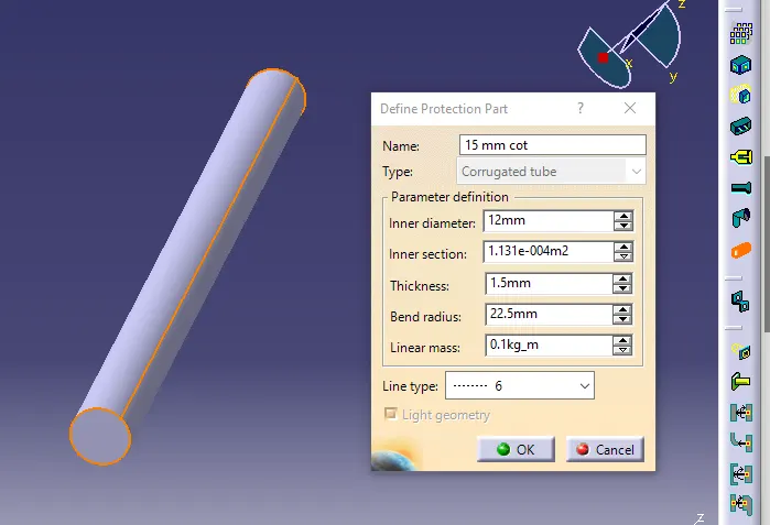
15mm COT,
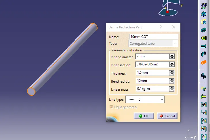
10mm COT,
5mm COT,
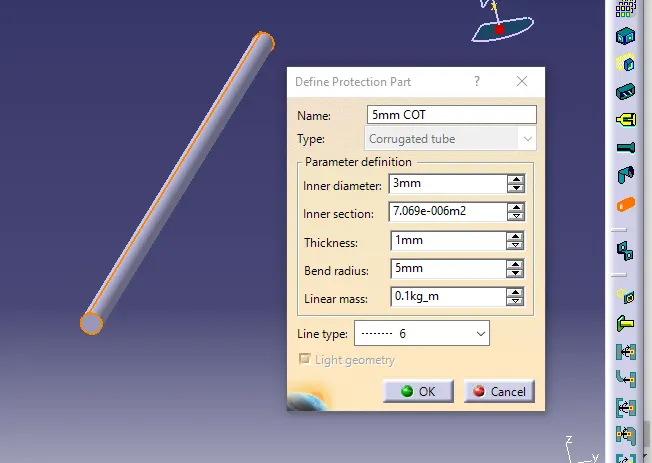
As per the inputs, the diameter and thickness value were used.
calculation of Bending Radius = Thickness * Outer Diameter
e.g. Bending radius For 35mm COT = 1.5 * 32mm
= 52.5mm.
Catalouge:
catalouge is develooped to add or store n number of created parts which are going to be used frequently.
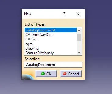
creation of catalog document
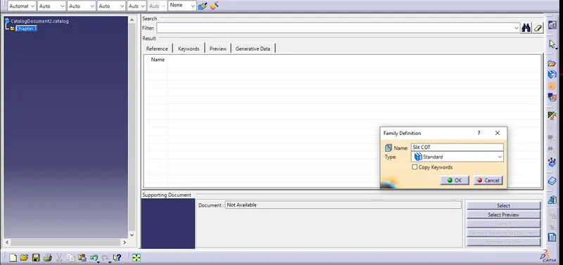
Addition of family in catalog.
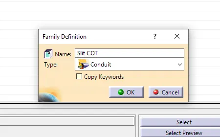
Define family.
store Device: All the created currugated tubes are stored and saved in the "SitCot" family.
Results:
P Clamp,
Backshell,
Corrugated Tubes,
Conclusion
1. Thus the p clamp has defined along with all the necessary parameters are defined.
2. The backshell has defined as Electrical Support along wth the necessary properties.
3. As per the given inputs, All the required corrugatedtubes are created and all the parts are stored in the family of ''Slit_cot" family of catalog succesfully.