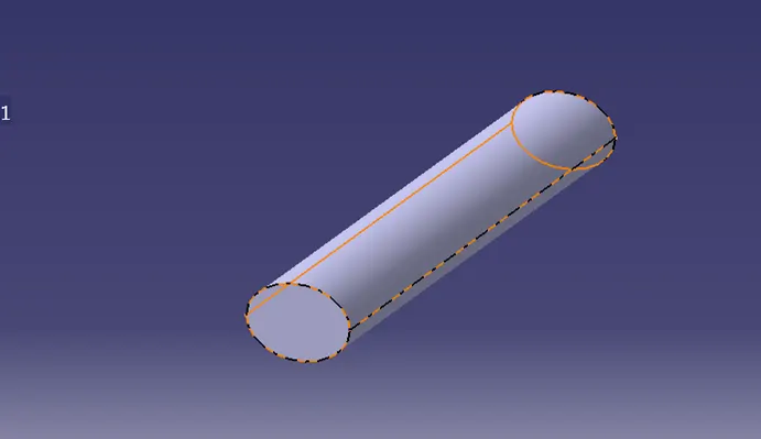
Wiring harness routing & packaging Rules Week 3 Challenge
Q1. Download the following cad data & define it as Electrical support using the Electrical Part Design Workbench. Define all necessary properties.
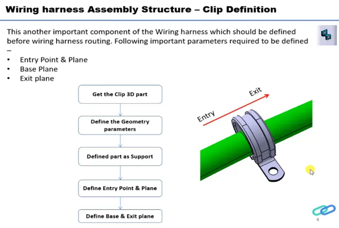
Process:
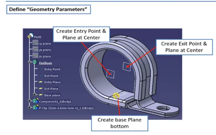
- Create two points, one as an entry and another as an Exit point.
- Create planes at two points and another at the base.
- Switch to Electric part design
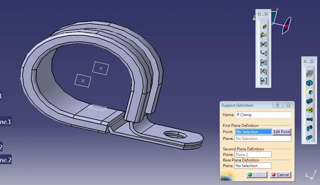
- Click on support definition - select part - select entry point - select entry plane, exit, and base plane.
- Again Click on the support definition - select part - select exit point - select exit plane and base plane as the second plane is automatically taken.
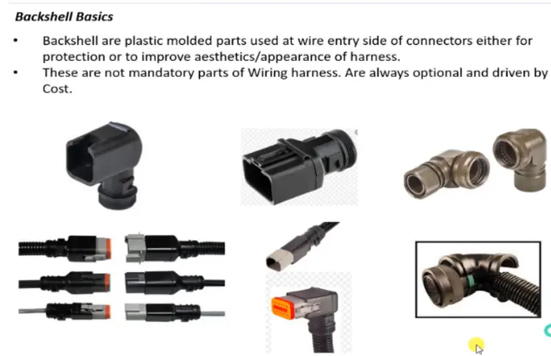
Q2. Download the following Back shell cad data & define it as an Electrical back shell using the Electrical Part Design Workbench. Define all necessary properties.
Tyco 1738312-1 https://www.te.com/usa-en/product-1738312-1.html
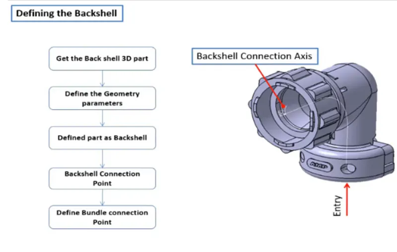
Process:
- Create Back shell entry points.
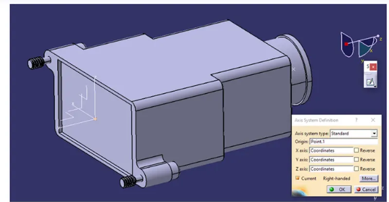
- Create an axis system for back shell entry.
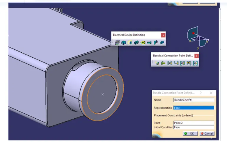
- Create a bundle connection point.
- Switch to Electrical part design.
- Define part electrically as a back shell.
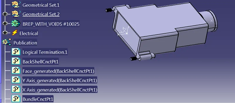
- Then define the Backshell connection point.
- Define bundle connection points.
Q3. Create Following Corrugated tubes & Add them in Catalogue under “Slit COT” family.
|
Name |
ID (mm) |
OD (mm) |
Thickness (mm) |
|
15mm COT |
12 |
15 |
1.5 |
|
20mm COT |
17 |
20 |
1.5 |
|
35mm COT |
32 |
35 |
1.5 |
|
10mm COT |
7 |
10 |
1.5 |
|
5mm COT |
3 |
5 |
1 |
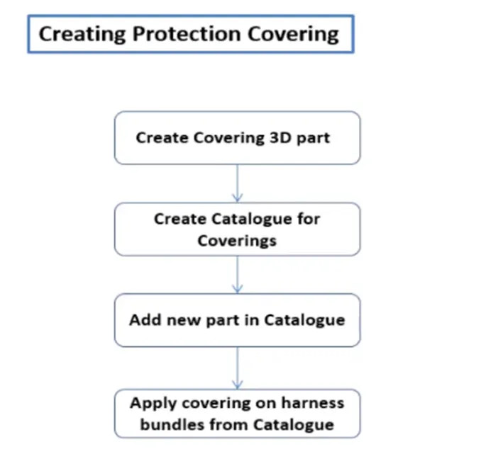
- We define the cot tubes in the electrical part workbench.
- The inner dia & thickness are given as inputs.
- A catalog was created for the cot tubes.
- All the cot tubes were saved in the catalog.