Week 8 - Challenge 6 - Core & Cavity Design
Aim-
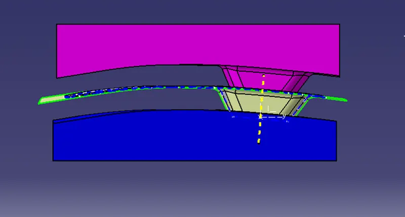
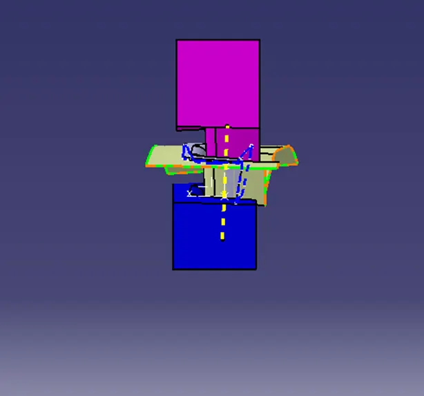
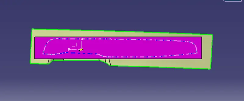
Create Core and cavity blocks for the switch bezel designed in the earlier challenge.
TOOLING AXIS-
The tooling axis of the product tells us the direction of movement where the part is being produced effectively.
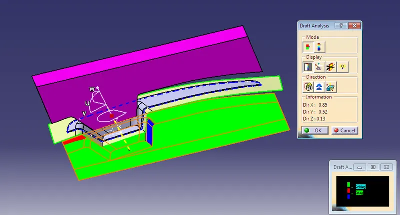
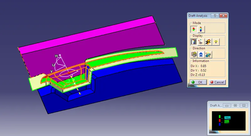
- Considering the ejection from the cavity of the mold after manufacturing the interior trim (switch bezel) must have a nominal 3-degree draft angle.
- Hence the tooling direction is created by considering the above factor and bisecting method is used.
- The base surface of class – A was extracted and a point at the center was created and an axis system was inserted to the point with the current feature disabled.
- Then, a project intersection along the YZ plane was created and the two inclined lines were drawn inside the positioned sketch.
- Then bisecting lines with the two inclined lines were drawn.
- Now the same procedure is done along the XZ plane but on one side we don’t have inclined lines so the center point is used to extrude a line along the z-direction and gave a measurement of 5 degrees (Tentatively).
- With these two lines from sketches 1 and 2, the bisecting line is created and published as Tooling Axis (tooling direction).
DRAFT ANALYSIS:-
SOLID PART IMAGES