Week 9 - Attachment Feature Creation (Ribs & Screw Boss) - Challenge 1
Part Not saved properly
As per discussion with T.S.E., I have submitted the report.
Aim-
Create a rib for the Drill Handle considering the design rules
Make the thickness of the component to be 3 mm
INTRODUCTION:
CLASS-A SURFACE:
A surface made by the designer is given as an input to the plastic modeler to work on. It has an aesthetic surface and the outermost surface.
CLASS-B SURFACE:
A surface below a certain thickness from the class-A surface is a class-B surface. This is the surface that contains engineering aspects of a model.
CLASS C SURFACE:
A surface that joins class-A and class-B surfaces is a class-C surface.
TOOLING AXIS-
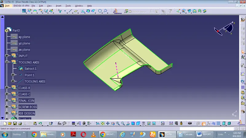
- It is defined as the direction in which the mold/core and cavity open. Selection of the direction of the tooling axis depends on the ease at which components can be easily ejected.
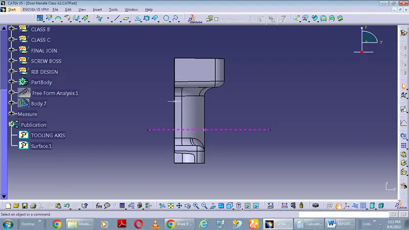
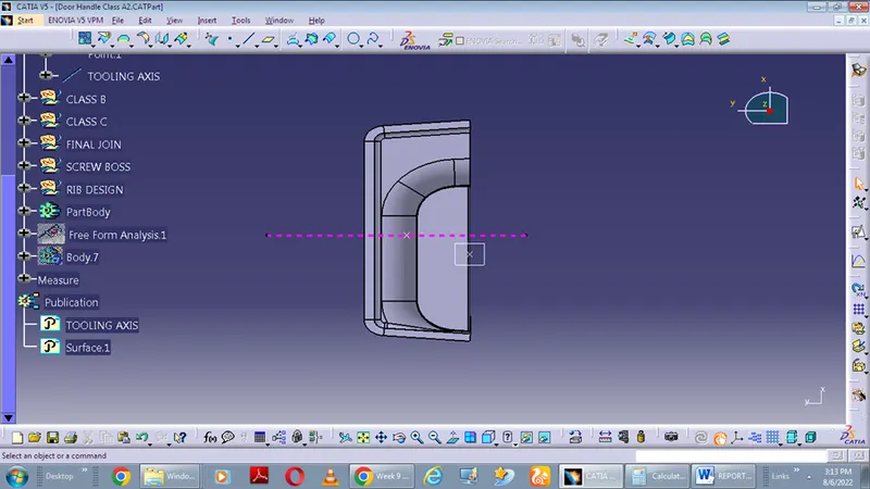
- By analyzing the component the most easily electable direction is somewhere close to the Z direction,(might be inclined to it) so we have made a sketch on the YZ plane of the Axis System) to create a bisecting line considering the 2 faces which might be difficult to be tooled.
Draft Analysis
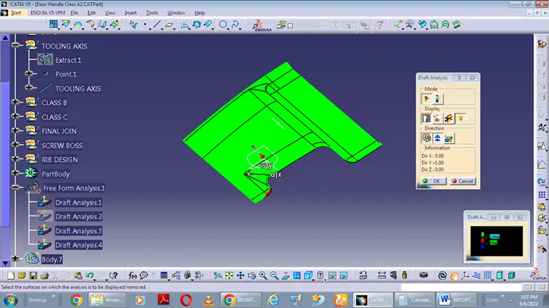
Draft analysis is a method used in design to check whether the component created in CAD is manufactured based on the draft condition applied. The main reason behind the draft analysis is the part manufactured should be easily removed from the mold. It also gives an idea of the draft angle from the tooling direction. Here we are giving a tooling direction in order to eject the component easily from the tool. The ideal draft angle given to automotive industries for plastic components is 3 degrees.
CREATING THE RIB
Ribs are thin wall protrusions that extend perpendicularly from a wall or plane. They are usually found in clusters offering support to a plane that would have otherwise been too thick, but can also be stand-alone support for a single wall. They are commonly used to provide additional support and strength to a part. Thickness and location are essential to rib design.
First, the base surface where the rib has to be created is extracted using the Extract command. A positioned sketch is created and the profile for the rib is drawn.
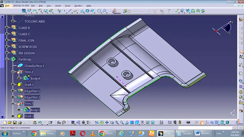
CREATING A SCREW BOSS
Screw Boss features are commonly found in injection molding designs. They are used to aid in the assembly of molded parts by providing a channel for a screw. Their primary use is to strengthen holes or slots in the surface present in the part model.
Design rules considered while creating a screw boss
- Thickness
- Draft
- Optional radii
- Boss Gussets
- Type of ejection
The construction process for creating the screw boss is explained below:
For thickness, the design rules are as follows,
Thickness, w=0.6*T
=0.6*3
=1.8 mm
Therefore, the thickness of the boss can be 1.8 mm per side.
In this case, we have considered the size of the screw boss as M06.
Part images