Week 8 - Challenge 1 - Base Bracket Design
ANS-
REPORT
Aim-
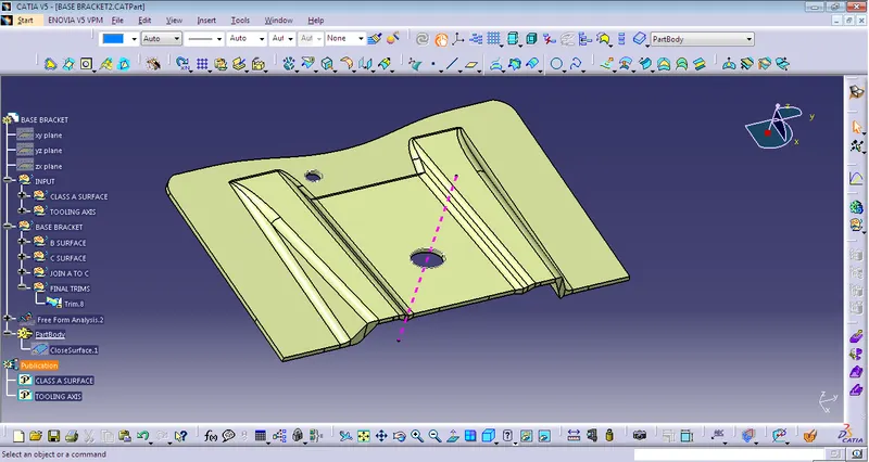
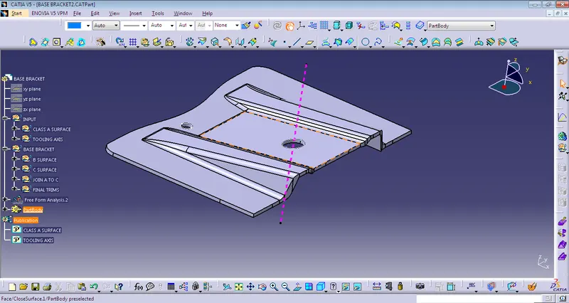
Create a Base Bracket Plastic component through the given Class-A surface. To begin with, the tooling axis for the given Class-A Surface should be created meeting the requirements of the draft angle and at the end perform the Draft analysis on the model.
TOOLING AXIS-
The tooling axis of the product tells us the direction of movement where the part is being produced effectively.
STEP-01
Connectivity of Class-A surface checking the connectivity of the surface can be done by creating boundaries or by simply using the join option such that any openings can be easily visualized.
STEP-02
- Analyze visually for the best possible tooling axis.
- The dummy tooling axis will be directly created using the point-direction command.
- Check possibilities (clearances) in all the directions of the axis and find out what the problem creation parts of the component or model are.
- The clearance check along all the axis directions will be done by creating an intersection along an axis on a plane with the model and constructing two lines in contact with the walls, the line bisecting the two lines and passing through the point will be the tooling axis.
- Creating intersections and Tooling axis for checking along Y-Axis
- Using the intersection, lines will be created along the inclined walls. These lines are used for the creation of the tooling axis by a bisecting method where the two lines and points will be selected as inputs.
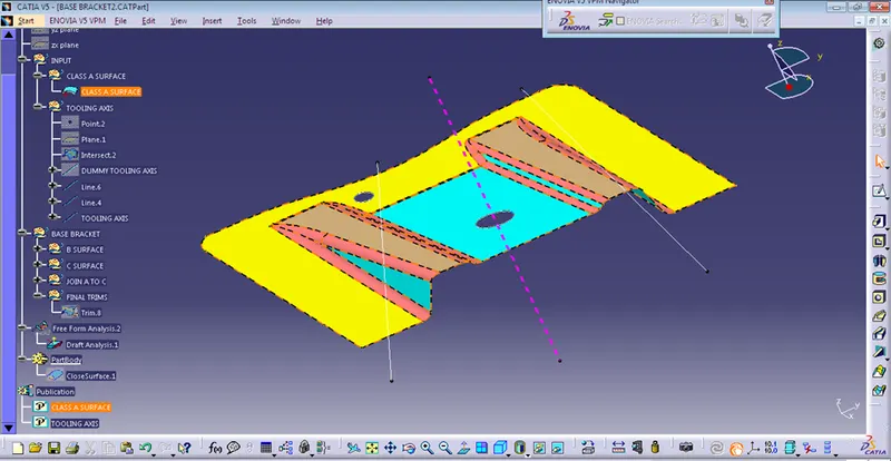
Draft Analysis:
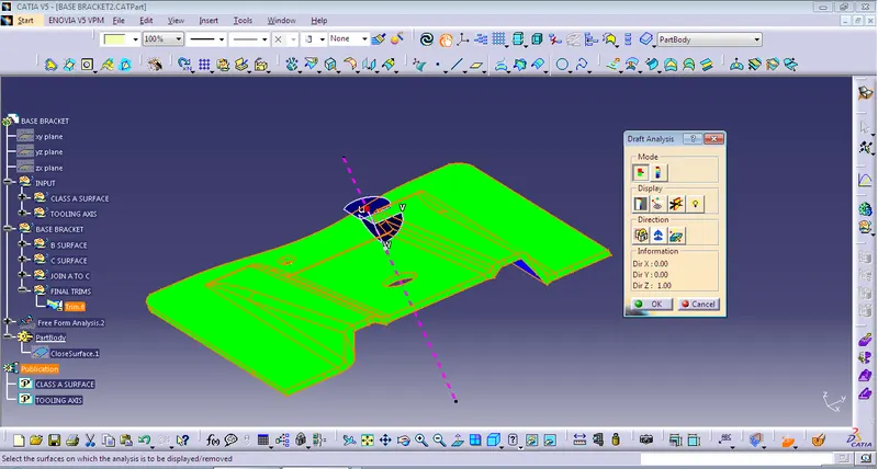
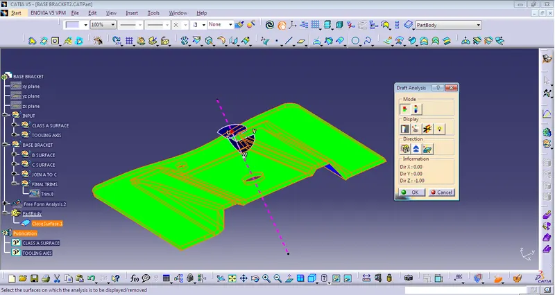
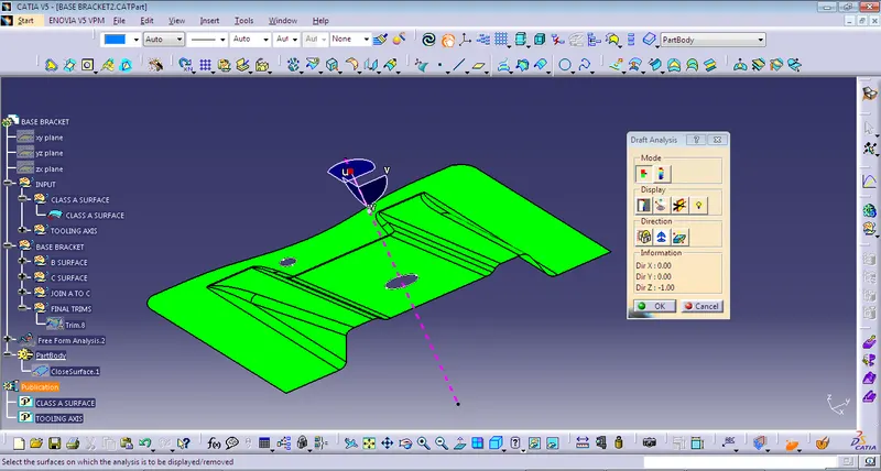
- Draft analysis is done after determining the tooling axis, draft analysis is used to check whether the minimum draft (3 degrees) is maintained or not.
- Compass is used to define the draft direction.
# Class A draft analysis
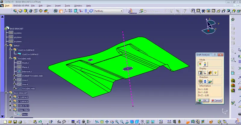
# Close surface draft analysis

SOME IMAGES OF THE PROJECT