Wiring harness design in CATIA V5 - 3D modeling Week 7 Challenge
Aim
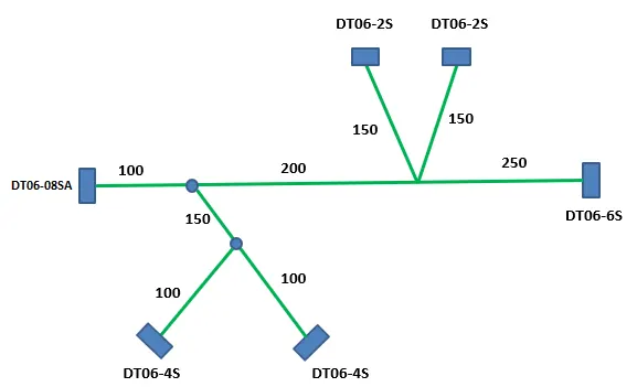
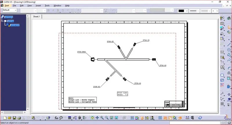
To Flatten the harness assembly and place the flattened view on drawing sheet. By bundles with protective coverings has different visuals on drawing view.
Procedure
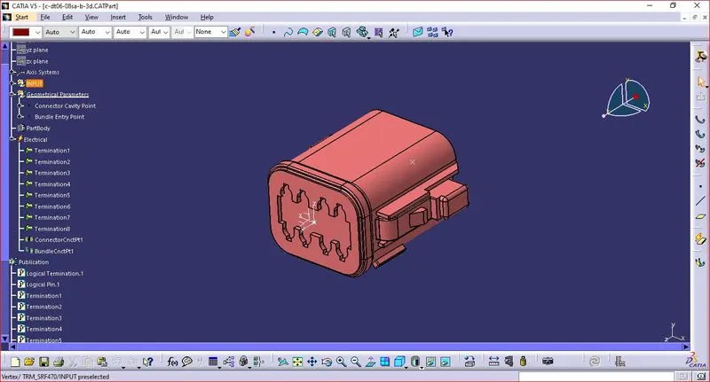
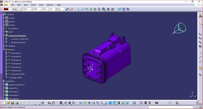
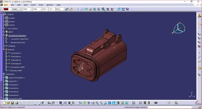
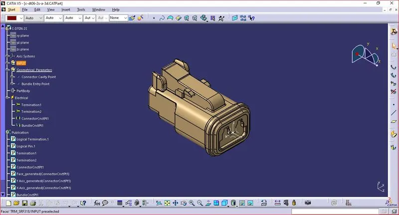
Step 1: Define the Mechanical Connectors Electrically.
- Creation of connector connection point and Connector Connection Axis
- Make a midpoint on the contact face for wire bundle insertion.
- Create an axis system referencing the newly generated point and specifying the axis direction.
- The Y-Axis should be oriented towards the connector's front face.
- The X-Axis should be oriented towards the clip's locking mechanism.
- The Z-axis should be pointing across the connector from left to right.
- Creation of Bundle Connection Point.
- Define the part as a connector
- Define connector connection point.
- Define Bundle connection point.
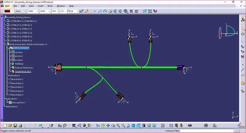
Step 2: Arranging the Connectors & Creating Multi-Branching to the connectors as per the design.
Branches diameters are 10mm and 5mm
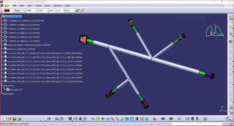
Step 3 : Creation of Protective covering.
Create the protective covering with Cot tubes of 10mm and 15mm
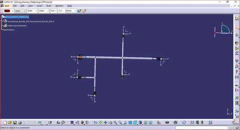
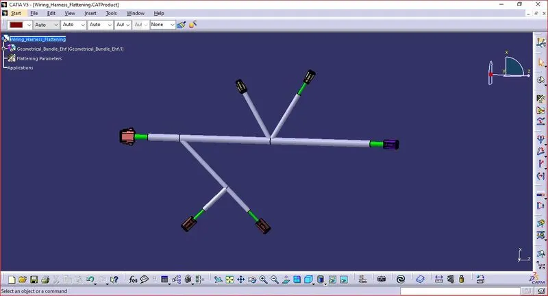
Step 3 : Harness Flattening
- Define the "Flattening Parameters" in harness flattening Workbench.
- Extract the Harness assembly to the Harness Flattening Workbench.
- The patrs are assembled in a proper way that they are easily visible.
Commands for Modifications,
- Straighten : To straighten the Bundle
- Rotate : To rotate the bundles.
- Bend : To bend the Bundles. Similar to rotate, but radius is applied to the bundles.
- Quick rool : To roll the bundles with nearest point reference.
- Arrange Junction- equal angle : To provide same angle from Junction point.
- Scale : Scalling for bundles to adjust drawing view. (Fake scaling)
- Auto Update Flatten link / Remove Flatten Link / Manually update
- Synchronize
Step 3 : Harness Drawing
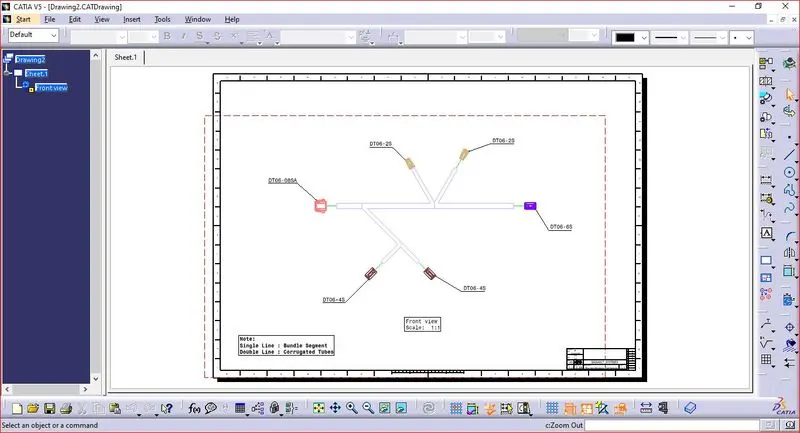
Conclusion
Thus the Wiring Harness Assembly is created in Drawing sheet Workbench by Flattening the harness assembly using Catia V5.