Wiring harness design in CATIA V5 - 3D modeling Week 7 Challenge
AIM:
- To flatten the wire harness assembly completed in week 4 assignment and place the flattened view on a drawing sheet.
OBJECTIVE:
- To flatten the wire harness assembly completed in week 4 assignment.
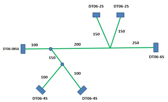
- To orient the wire bundle as shown in the layout.
- To place the flattened view on a drawing sheet.
- To ensure bundles with protective coverings has different visuals on drawing view.
Download connector 3D data from www.te.com
- DT06-4S
- DT06-6S
- DT06-2S
- DT06-08SA
Routing Procedure:-
DT06-2S:-
- Giving the necessary parameters to define it as connector.
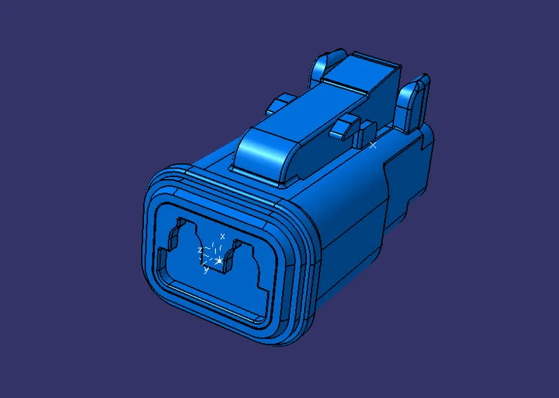
- Define it as electrical connector with 8 terminations.
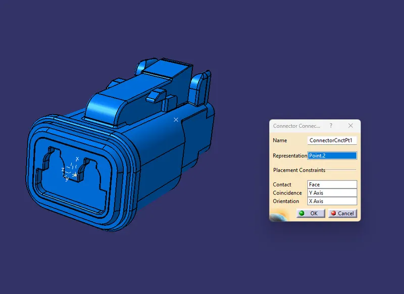
- Define the connector connection point at axis side to mate with another part.
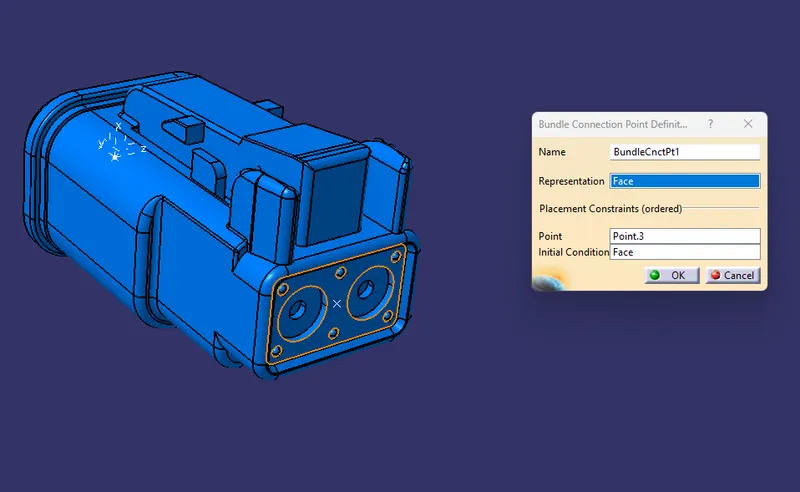
- Defining bundle connection point for wire entry.
- Saving the part into catlouge
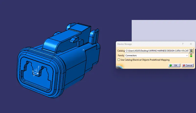
DT06-08SA:
- Giving the necessary parameters to define it as connector.
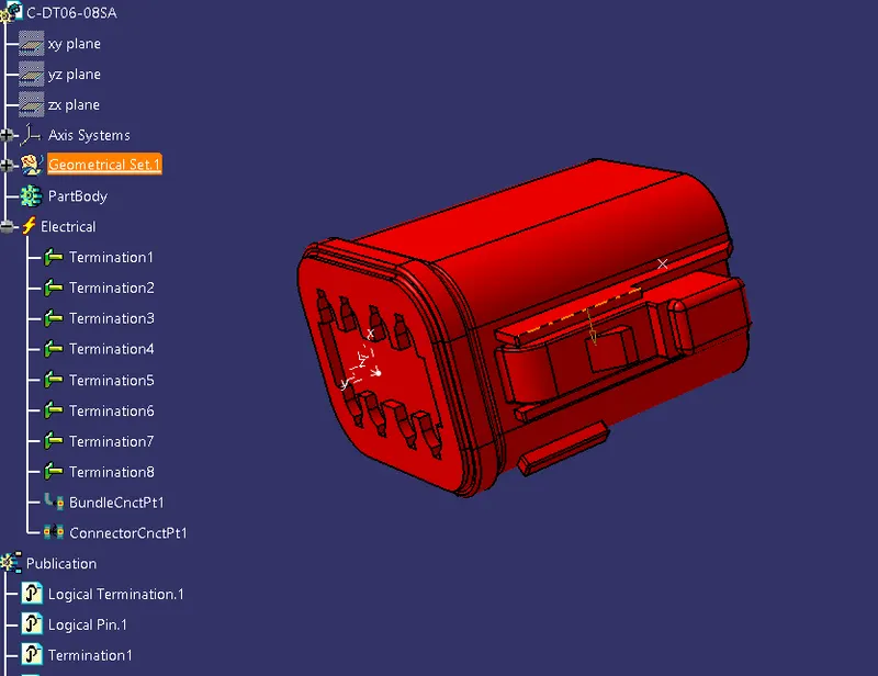
- Define it as electrical connector with 8 terminations.
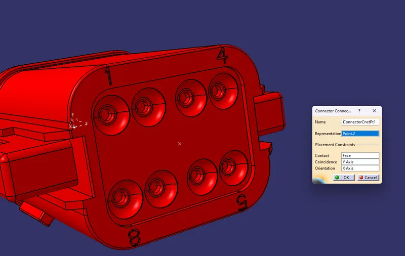
- Define the connector connection point at axis side to mate with another part.
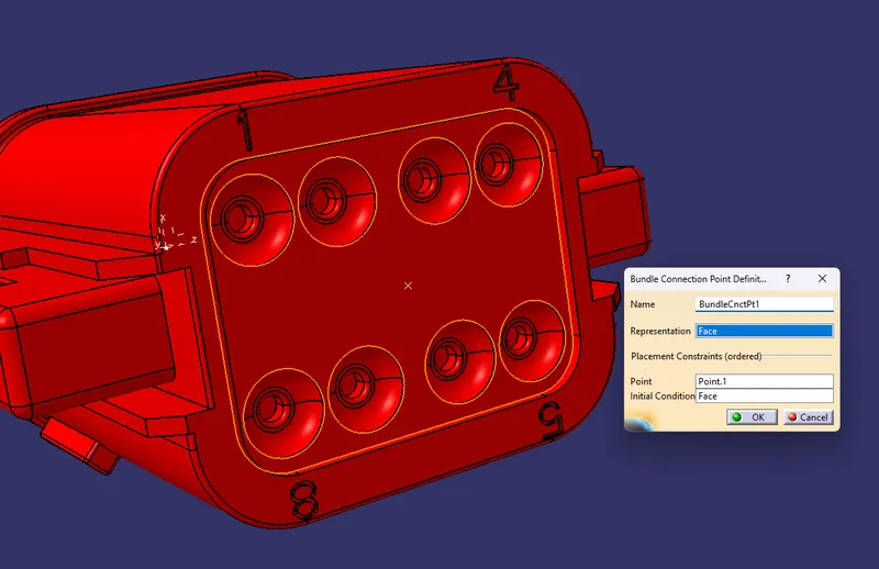
- Defining bundle connection point for wire entry.
- Saving the part into catlouge
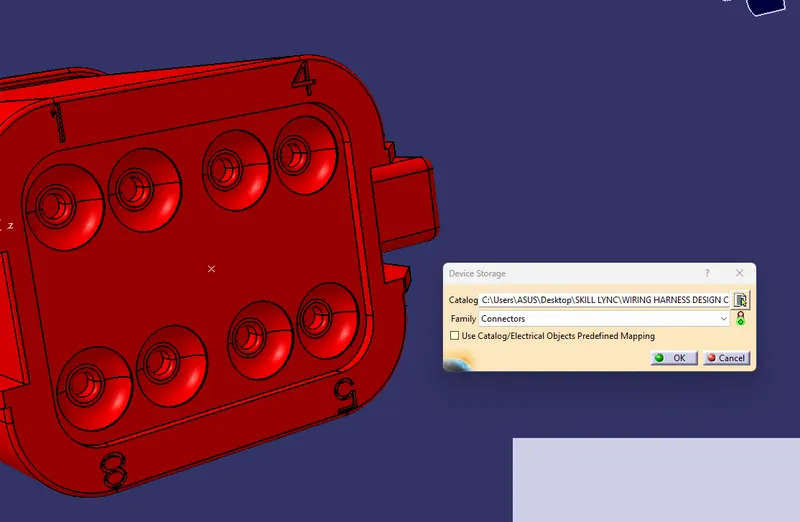
DT06-4S:-
- Giving the necessary parameters to define it as connector.
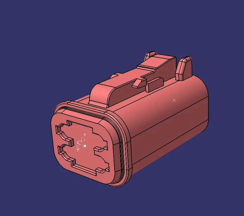
- Define it as electrical connector with 8 terminations.
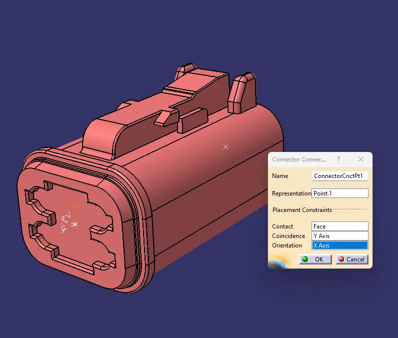
- Define the connector connection point at axis side to mate with another part.
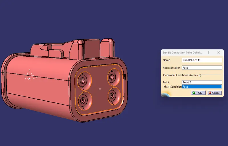
- Defining bundle connection point for wire entry.
- Saving the part into catlouge
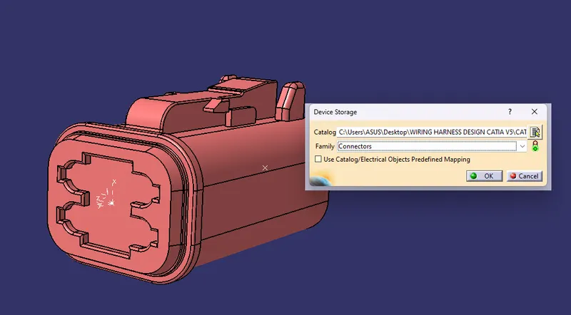
DT06-6S:-
- Giving the necessary parameters to define it as connector.
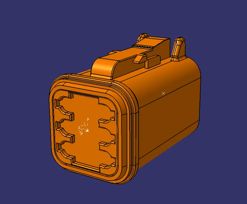
- Define it as electrical connector with 8 terminations.
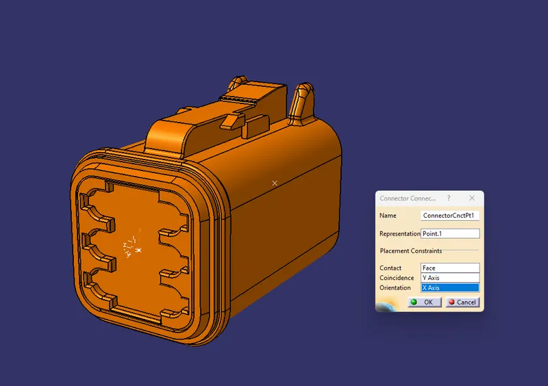
- Define the connector connection point at axis side to mate with another part.
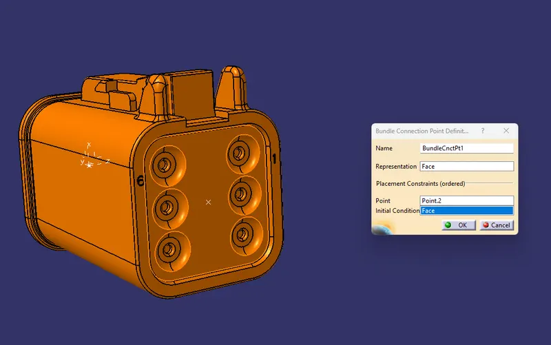
- Defining bundle connection point for wire entry.
- Saving the part into catlouge
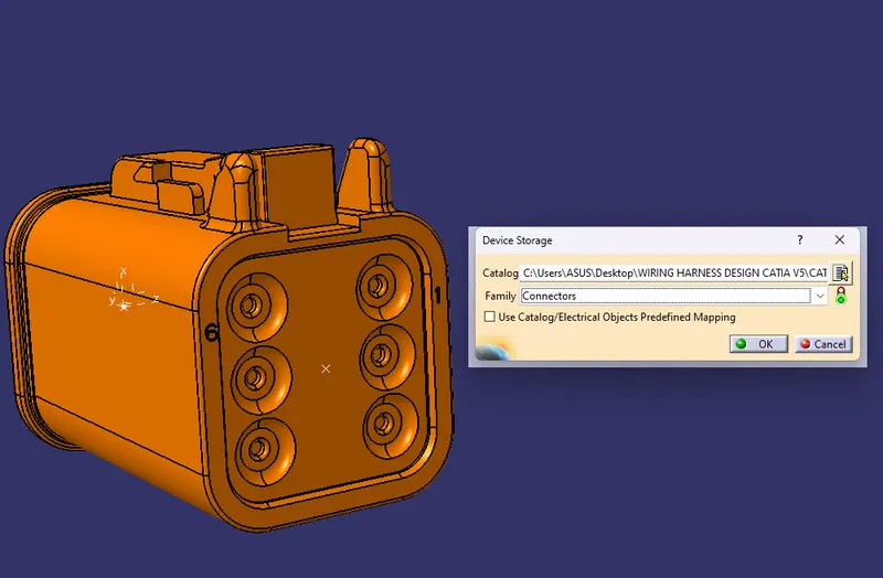
So like wise we need to define all the connector as electricaly.
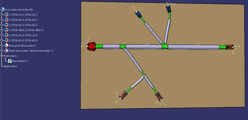
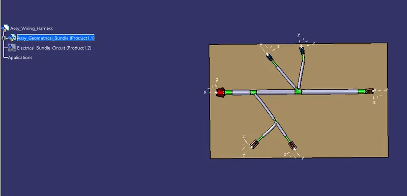
Now Create the Electric wire harness context assembly and Geometric bundle as a subassembly containing all the electric parameters as shown below,
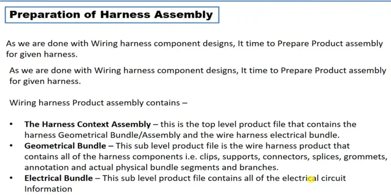
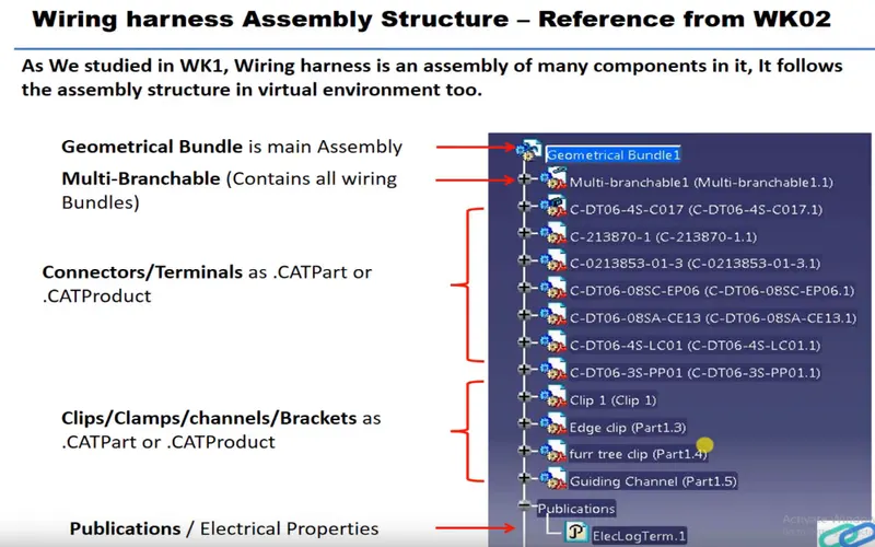
Add the all connectors which are electricaly defined to the Geomteric bundle assembly.
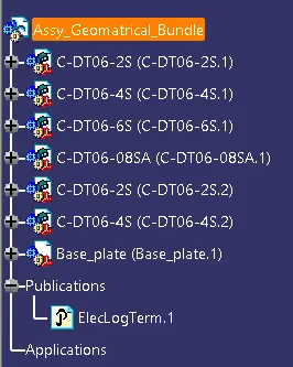
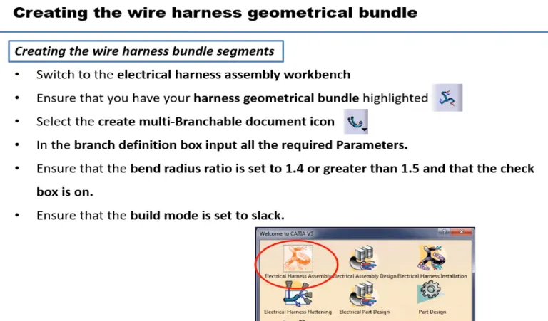
Then define this Geomteric bundle assembly as electricaly, for that we need to switch to Electric harness assembly workbench.

select Geometric Bundle then click on Geomteric bundle assembly (In specification Tree)
Now, to position all the connector as given in input file,
Create enviroment on which the bundle assembly will be placed.
Draw the sketch as given dimension in input just for referance purpose.
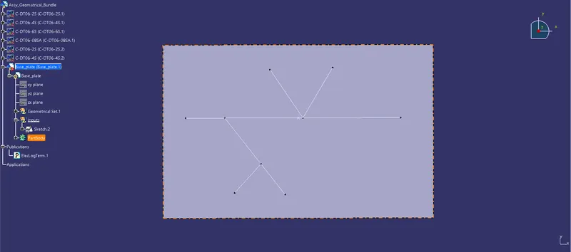
Switch to Mechanical assembly workbench, Position the connectors by using Manipulation, snap, smart move and compass commands.
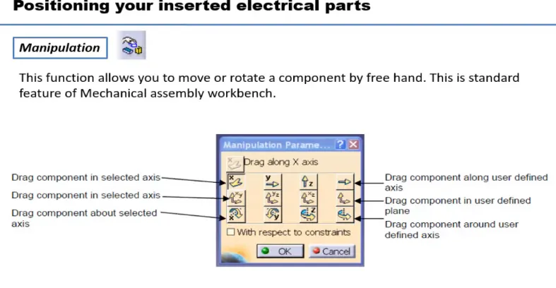
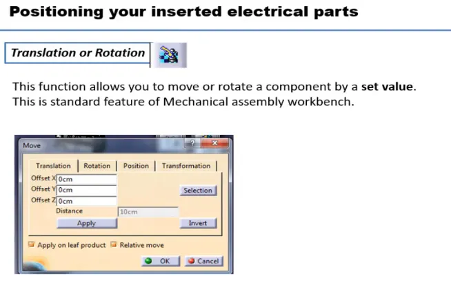
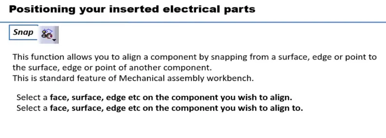
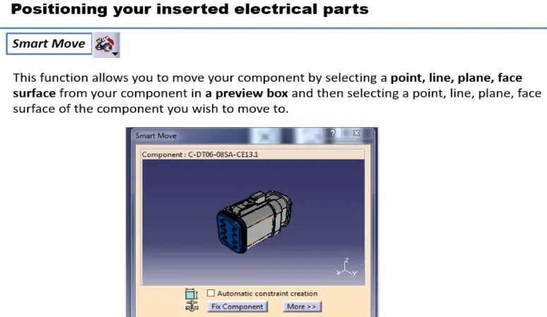

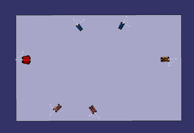
Now switch to Electric harness assembly workbench
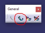
select multi branchable documents
Now to route the harness, after selecting multi branchable documents workbech changed to wire harness installation.
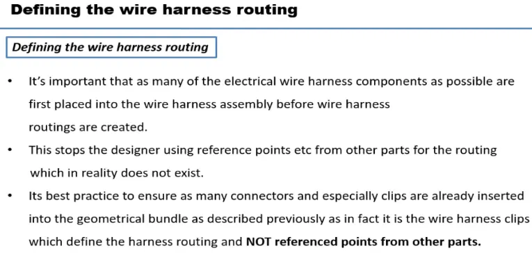
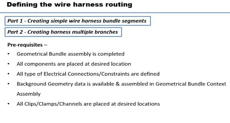
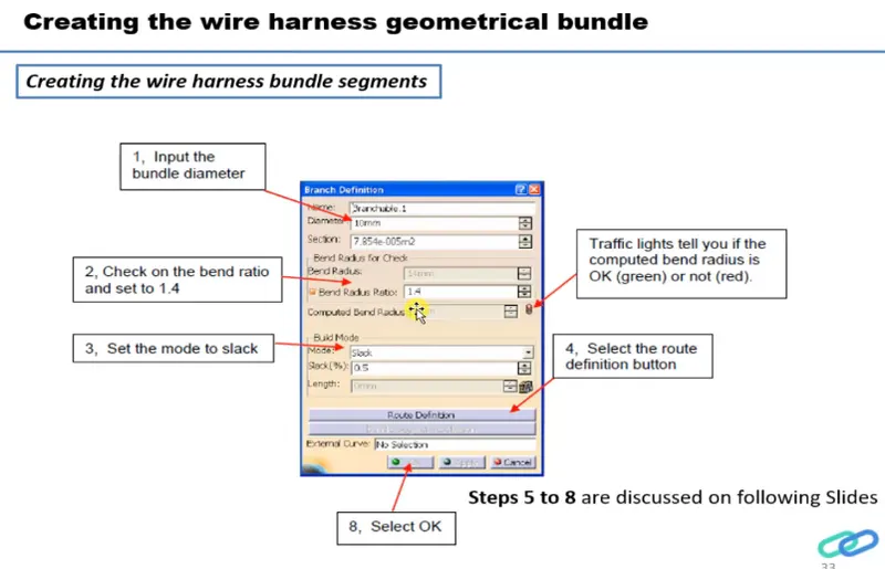
Click on Branch defination
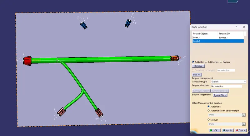
Then click on route defination
select connectors in between we want to create branch.
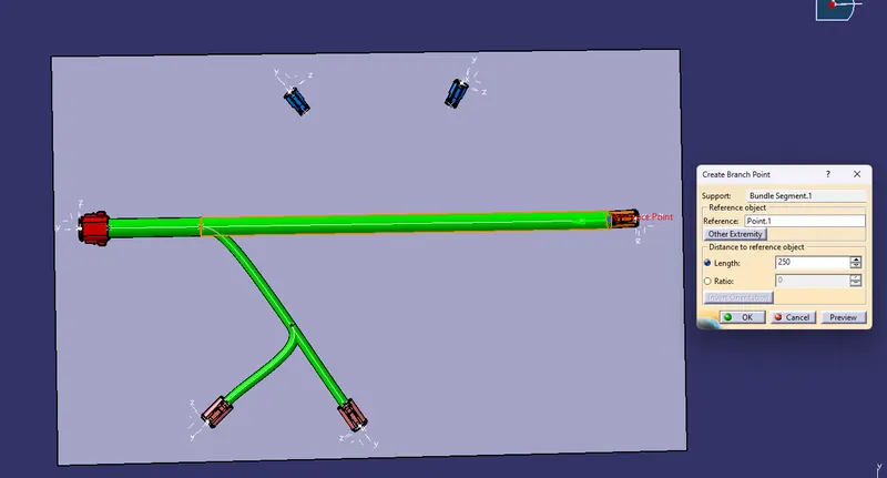
TO add branch point
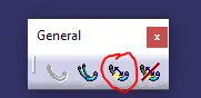
select the branch then give ratio or dimension for the point
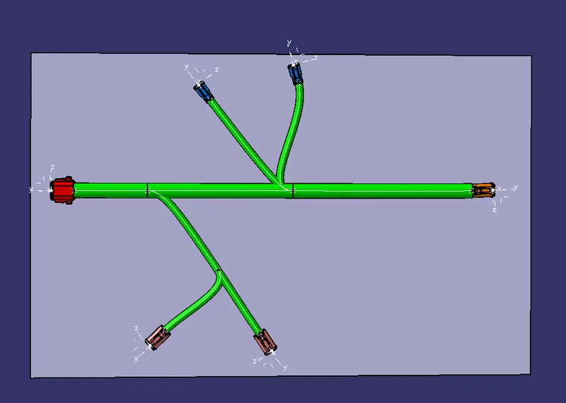
Final wire harness routing
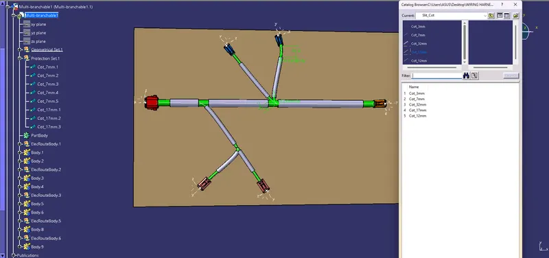
Now to create protective covering on all branches
switch to electrical harness assembly
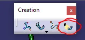
select protective covering then select branch - select catalog - select approprite slit cot tubes - give extrimity at start and end - ok
SOLUTION METHODOLOGY:
Step - 1:
- Create a product file and navigate to the Electrical Harness Flattening for wire harness flattening option and save it in the same location where the wire harness or routing assembly is stored.
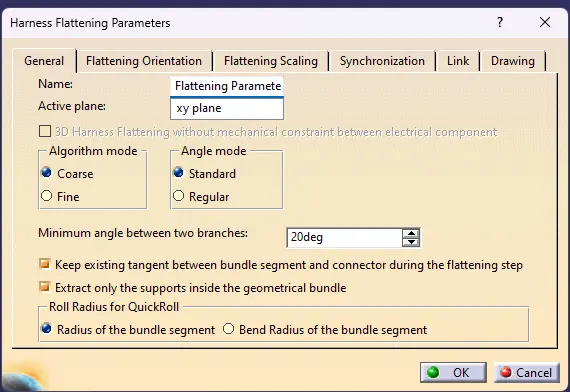
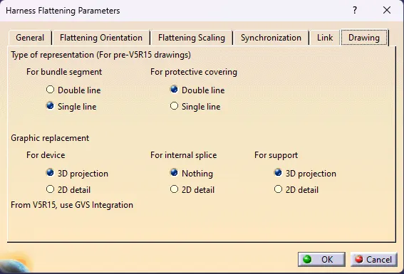
- Define the 'Harness flattening parameters' in order to flatten the required wire harness assembly.
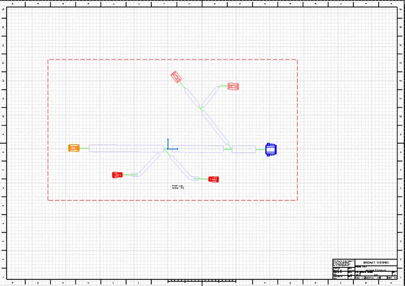
- While defining the harness flattening parameters in the drawing menu single line is selected for bundle segment and double line is selected for protective coverings in order to differentiate between the wire bundle and cot tubes in drafting.
Step - 2:
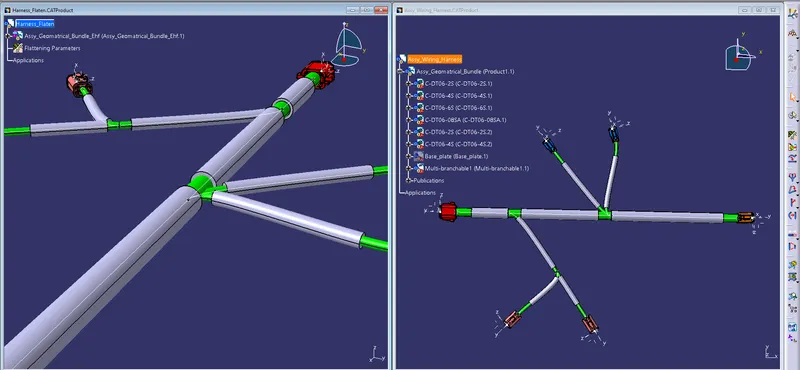
- Select the 'Extract' option from the Electrical Harness flattening workbench and select the Geometric bundle product in the wire harness assembly product file.
- Then wire harness assembly is imported to the Wire flattening product file with 'EHF' extension added to the geometric bundle assembly name.
Step - 3:
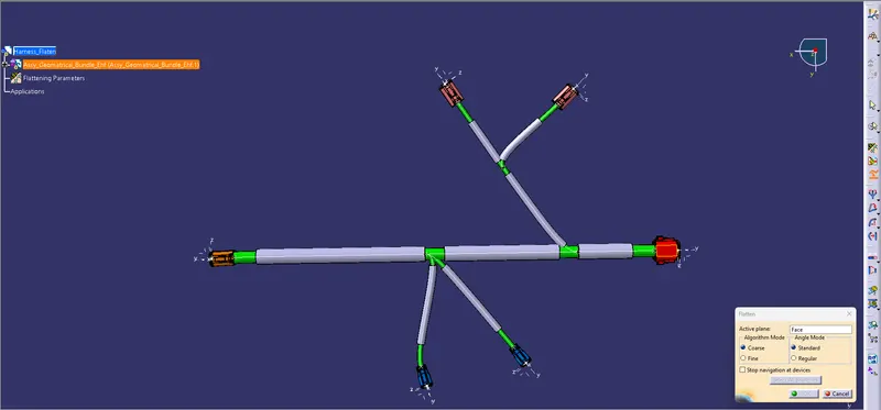
- Select the 'Flatten' option to flatten the wire harness assembly.
- Then select the active plane, then select any one branch and then select the 'select all branches'.
- If there is no discontinuity in the bundle segment then all the branches will be selected and by pressing 'ok' the wire harness assembly will be flattened.
Step - 4:
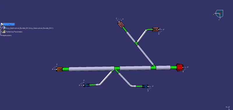
- Use 'Rotate' and other commands to rotate the branches and bring them in proper orientation as per the given layout.
Step - 5:
- Save the product file using 'Save management' option so that all the related product files and part files are stored in single directory.
FOR DRAFTING:
Step - 1:
- Create a new drawing file and save the file in the same location.
Step - 2:
- Insert the title block template and fill up the required details.
Step - 3:
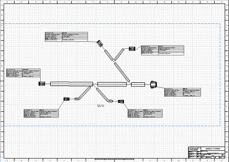
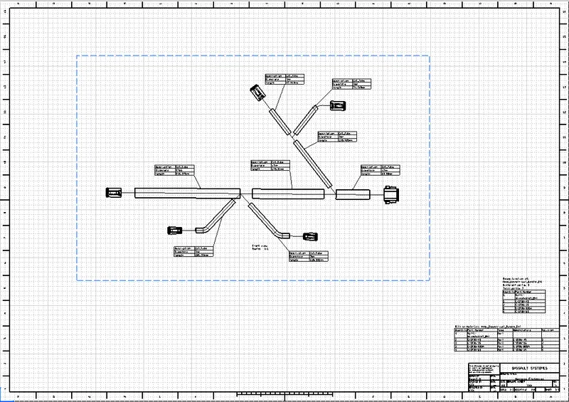
- Add the front view of the harness assembly by selecting any one of the flat faces of the connector and orient the view as per the requirement.
Step - 4:
- Go to the properties of the view and select the '3D Wireframe' on and ' Is always visible' option in order to see properly the Wire bundle, connectors and the protection coverings.
Step - 5:
- Show and name all the parts used in the wire harness assembly in form of a table.
CONCLUSION:
- From the above assignment we learnt how to flatten a given wire harness assembly and how to place the flattened view on a drawing sheet and show all its components.