Wiring harness design in CATIA V5 - 3D modeling Week 7 Challenge
Ans 1
Objectives
- Define the mechanical parts electrically
- Prepare bundle flattening
- 2D drawing of the bundle with connector representation and different color coding
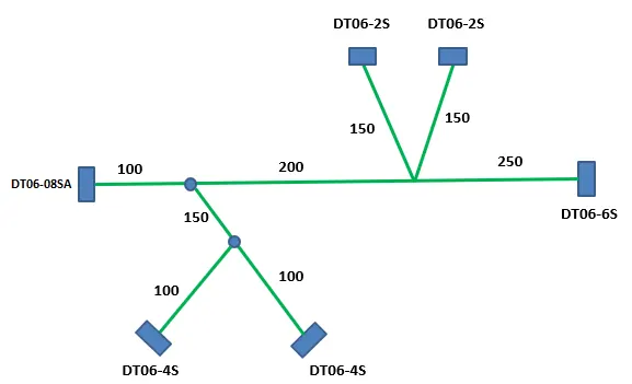
The layout to follow in this project.
Connector
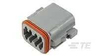
It is an electro-mechanical device used to join electric terminations and creates electric circuits.
Deutsch DT06 – 08SA
https://www.te.com/usa-en/product-DT06-08SA.html
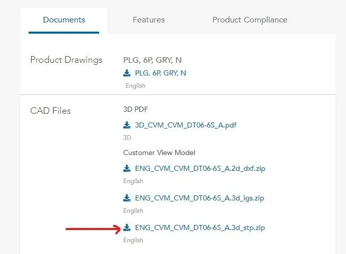
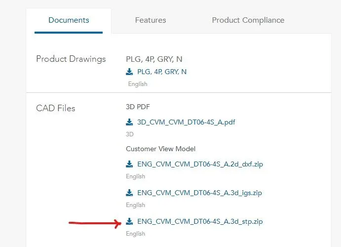
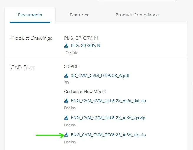
By using the above link we download the required part for our work
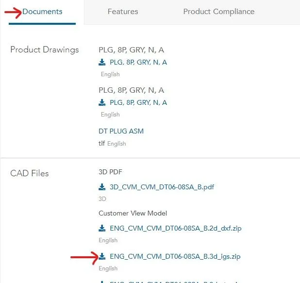
using the documents tab to download the cad file.
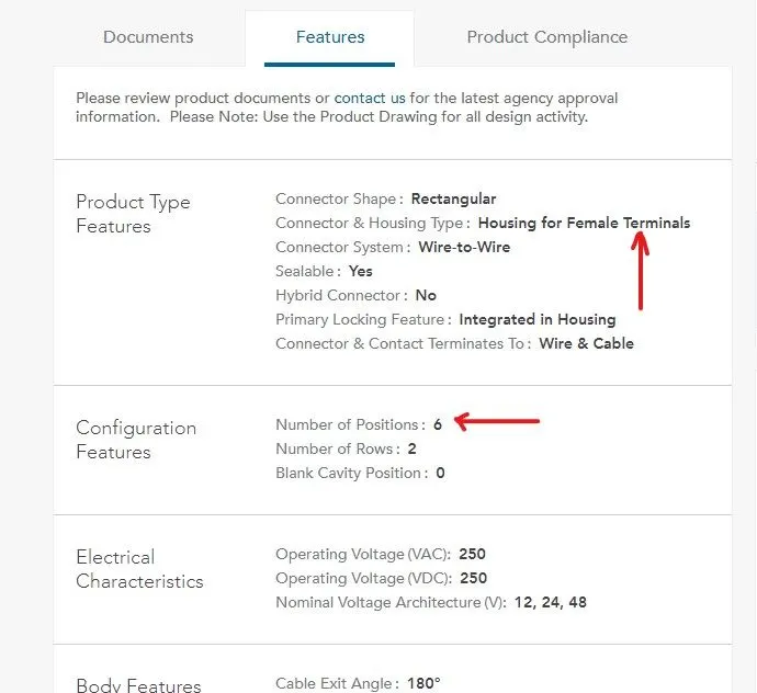
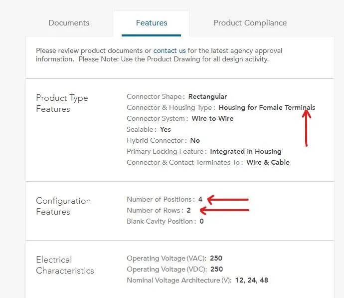
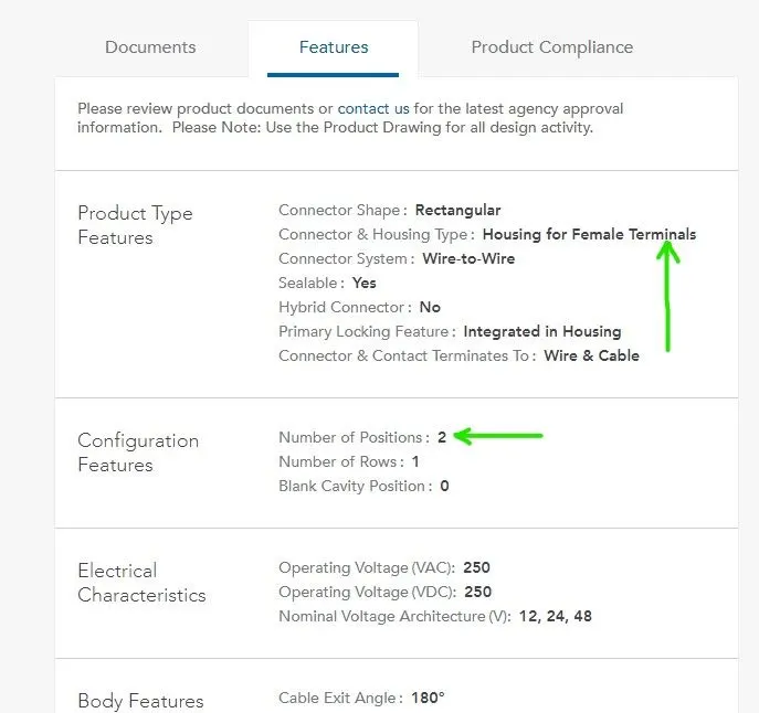
we can also see the properties of the connector before using it in our assembly by using the features option.
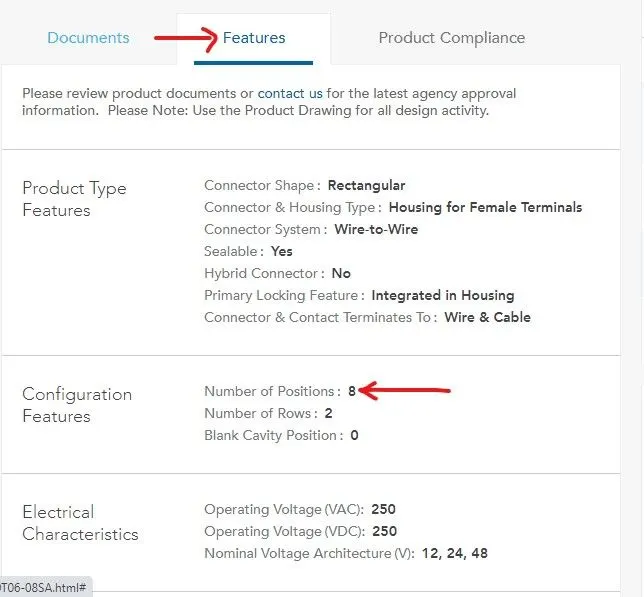
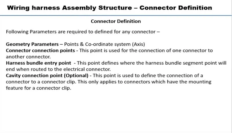
After downloading the required cad file we now move forward with the creation of the various parameters for our connector. For the creation of various parameters, we require the following point in the parts.
Bundle Connection Point
It is used to connect the wiring harness to the connector
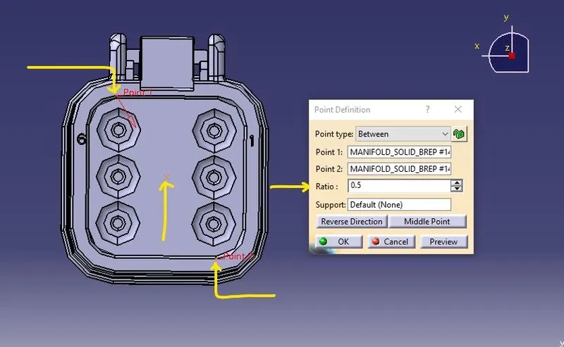
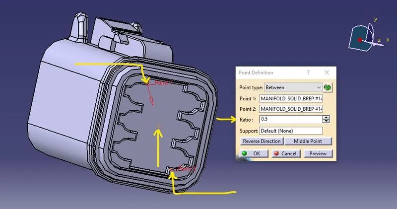
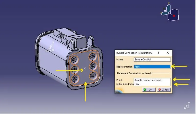
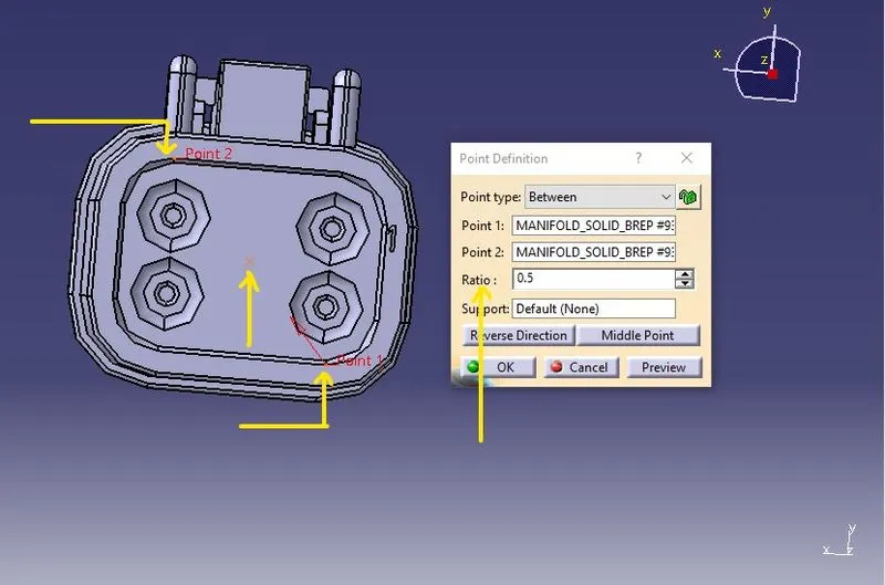
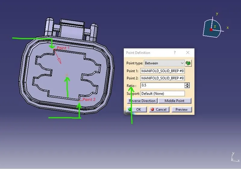
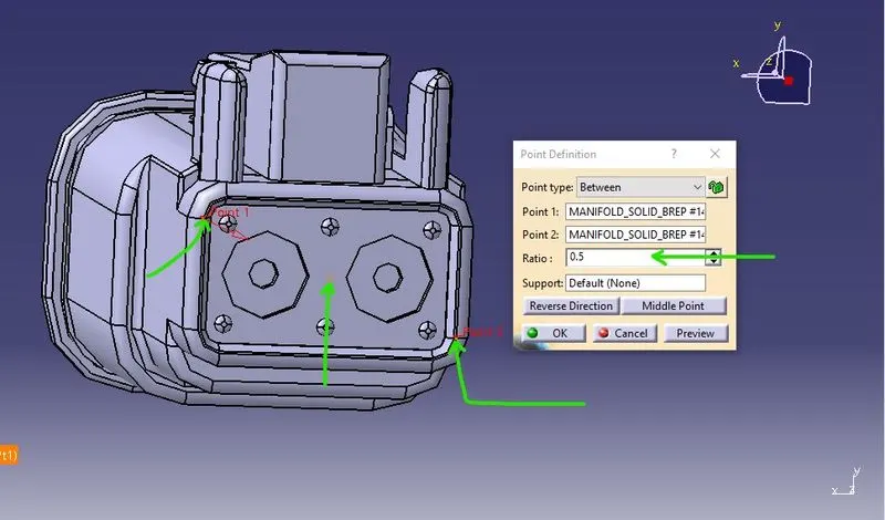
for the creation of the bundle connection point, we create the point at the midpoint of the termination side of the connector.
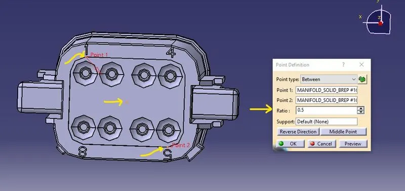
using the between type of point definition to create the point at the midpoint on the face select two points and give the ratio as 0.5 to create the required bundle connection point.
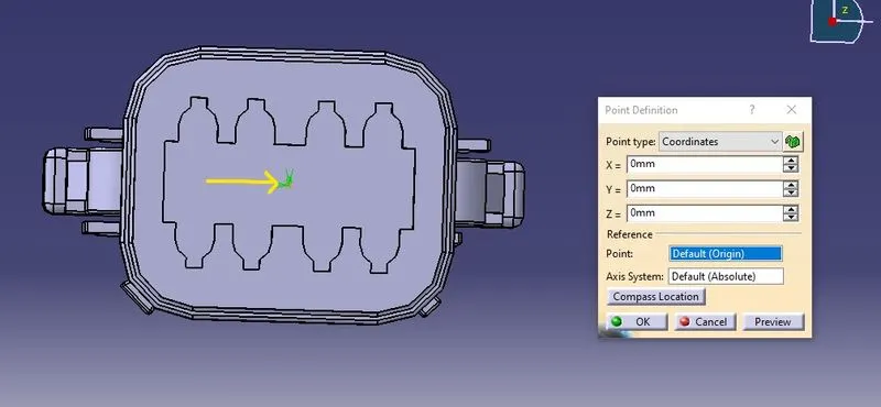
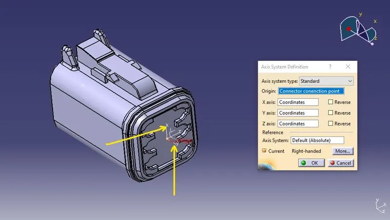
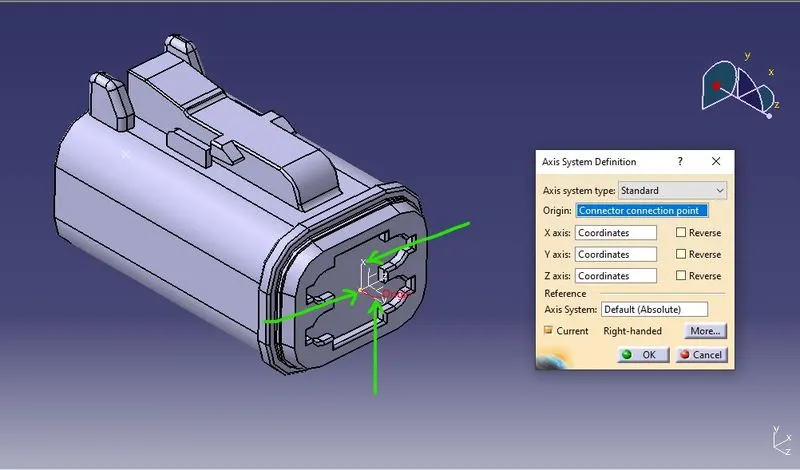
Connector Connection Point
It is used to connect the other device or connector to the main connector
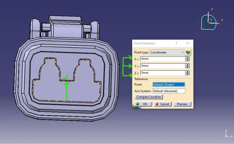
using the same process to create the point at the midpoint at the other face of the connector which is directly opposite to the bundle face.
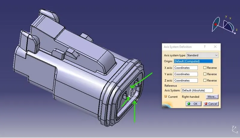
Axis
we must create the axis for the proper facilitation or for the proper seating of other parts with the connector.
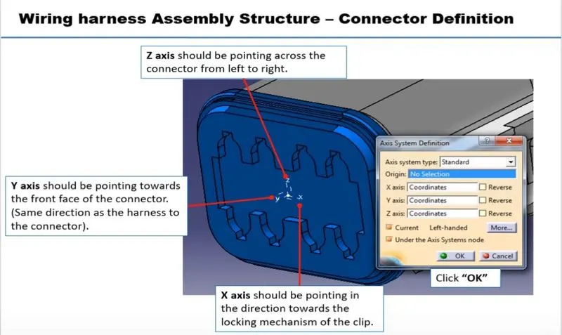
though these are not industry standards we need to be consistent with both mating parts in order to get proper assembly
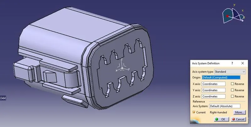
Cavity Connection Point
It is used to provide the connection between the mounting system of connector clips with the connector. It is the same as the Connector connection point we also need to create an axis here similar to the connector axis but is an optional point we created it only when we required the mounting part.
After Creating the various parameter required in the connector we now need to convert the mechanical part into the electrical component for this we are going to use the electrical part design workbench.
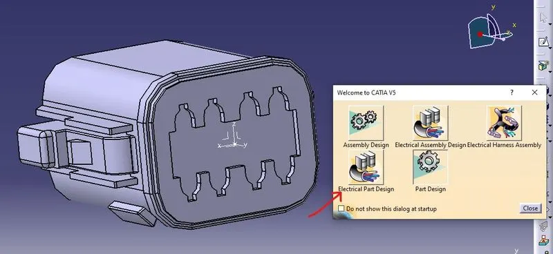
To convert the required part into the electrical component we use the define connector tool option
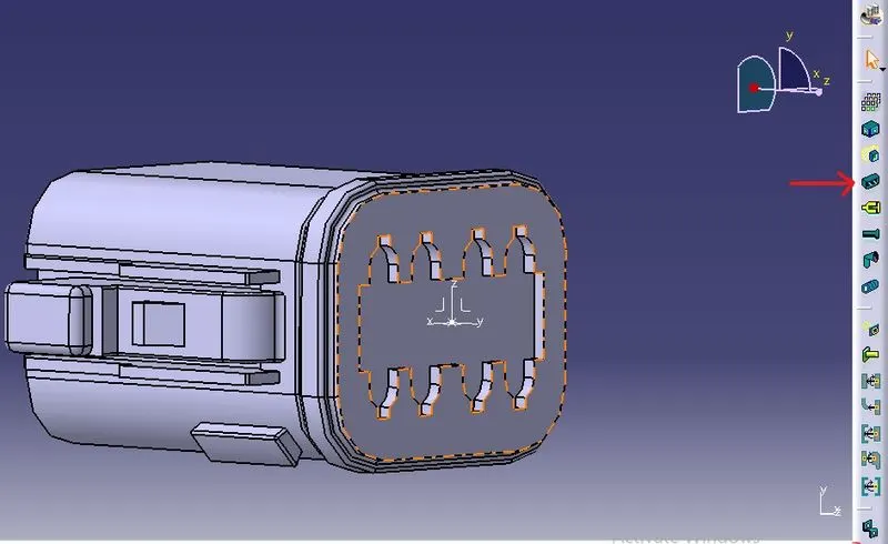
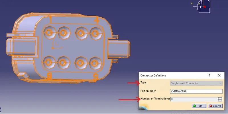
By simply choosing the connector type and the number of terminations we can easily define the part as an electrical connector.
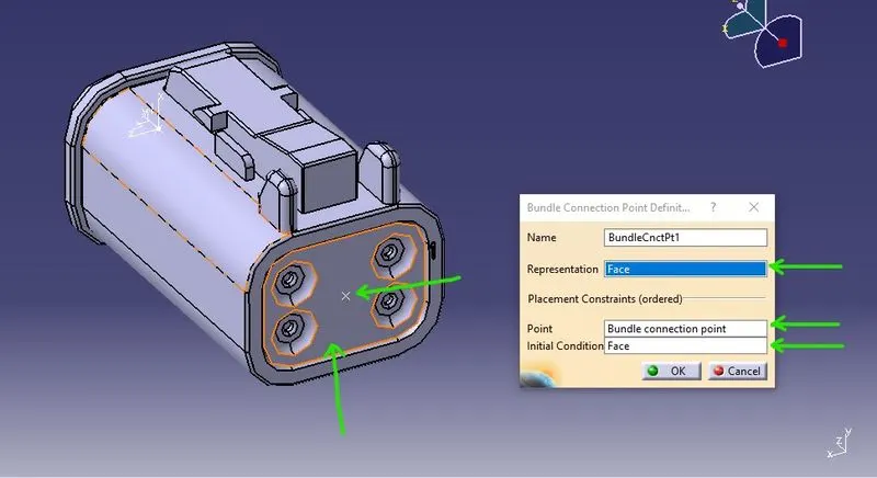
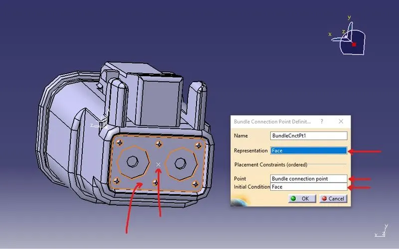
We now need to define the various point we created in the part workbench in the electrical definitions for that we use the bundle connection point to define the Bundle connection
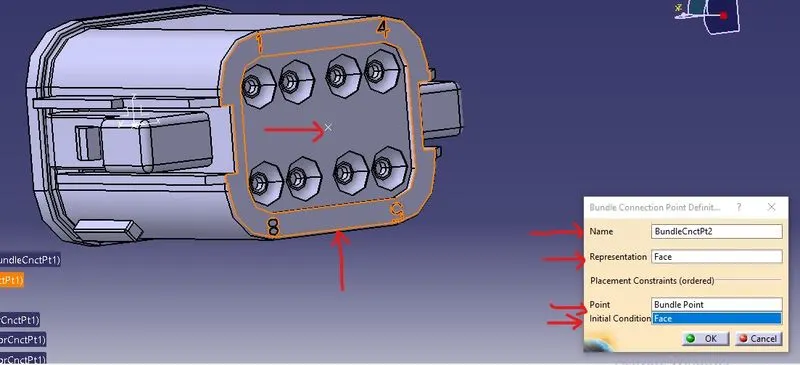
In the representation, we select the face which is normal to the bundle entry in the point we use the bundle point, and again in the initial connection we select the face which is normal to the bundle entry.
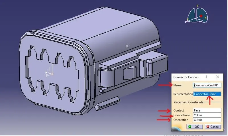
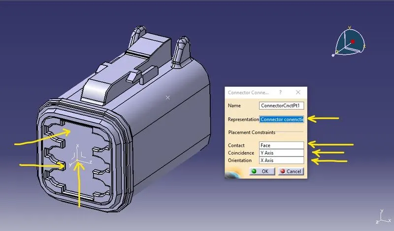
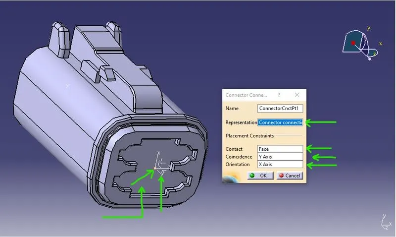
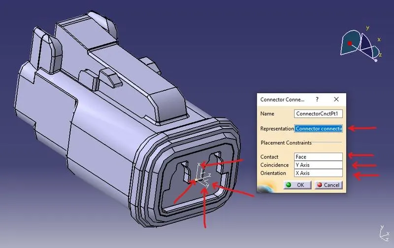
We now need to define the various point we created in the part workbench in the electrical definitions for that we use the connector connection point to define the connector connection
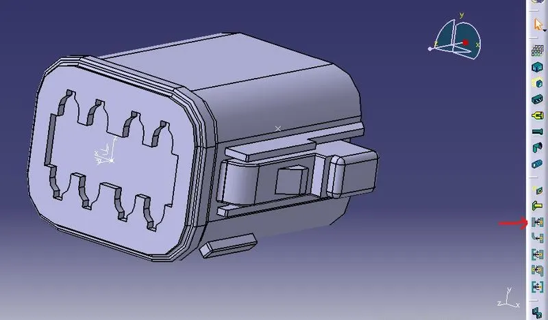
for that, we choose the representation as our already created connection point in the contact we choose which will go to be in contact with other mating parts we choose the coincidence axis as the Y axis where our parts move in and out for the assembly or in case of disjoining the parts and in the end we choose the orientation axis x-axis.
Similarly, we can use the same steps again for the other required parts.
DT06-6S
https://www.te.com/usa-en/product-DT06-6S.html
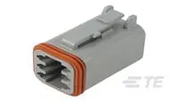
DT06-4S
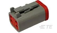
https://www.te.com/usa-en/product-DT06-4S.html
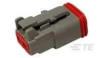
DT06-2S
https://www.te.com/usa-en/product-DT06-2S.html
after defining the connectors electrically we now move forward to assemble this connector in the wiring harness using the electrical wiring harness assembly.
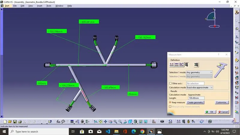
now we have a required electrical harness assembly which we need to flatten as per the objectives
For flattening the wiring harness assembly, we use an electrical harness flattening workbench.
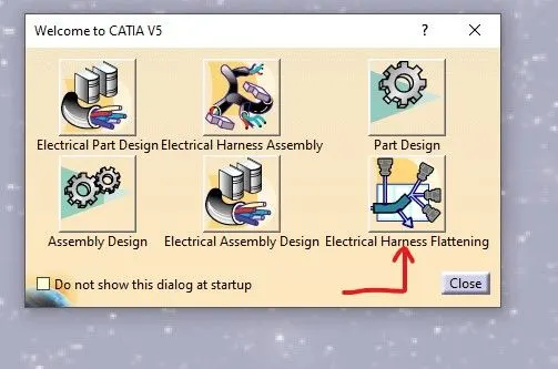
before flattening our electrical assembly we now require to set some parameters using the harness flattening parameters tool
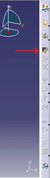
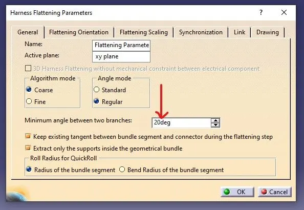
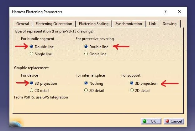
after setting up the flattening parameters for the assembly a file appears on the product tree which shows that we set up the parameters for the flattening assembly
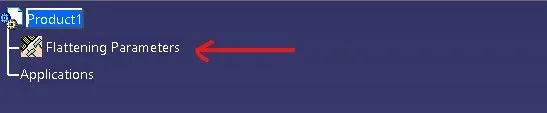
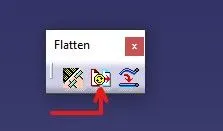
now for extracting the electrical assembly file into the flattening assembly, we use the extract tool present in flatten toolbar.
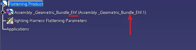
after extracting the required file. It is converted into the electrical harness flattening file which comes along with the short form EHF in the filename
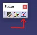
now to flatten the extracted file we use the flattened tool present in the flatten toolbar.
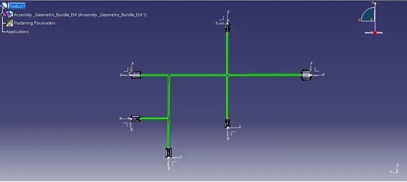
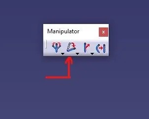
to arrange this flattened file as per our conditions we use the rotate tool present in the manipulator toolbar.
Final Flattened file.
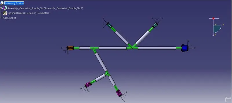
after the final flattening of the required file, we now move forward with the drafting of this file.
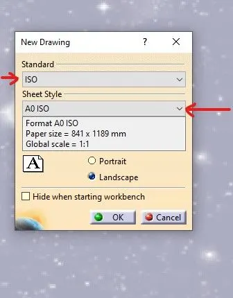
for drafting the flattened file we select standard ISO and sheet size as per our requirement
for extracting the required file we use the views option present in the view toolbar to extract our file in the drawing workbench.
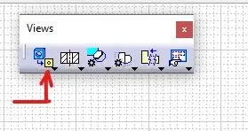
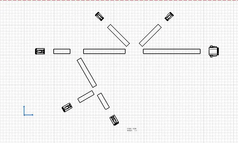
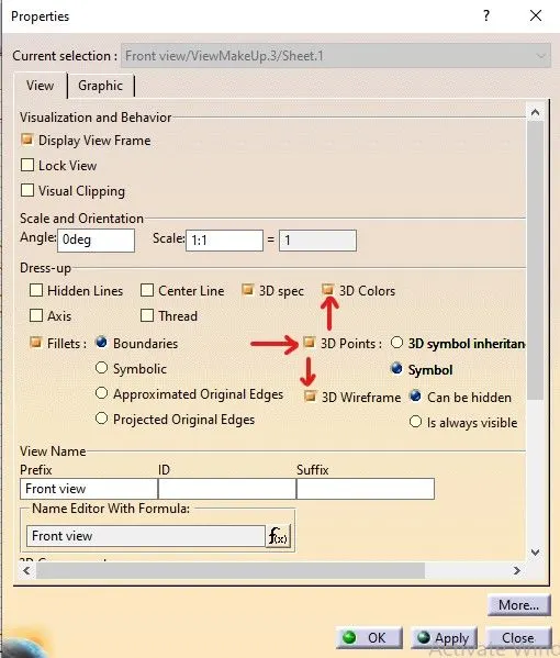
to get our view properly we now require to change the property so that the drafting drawing comes as per our requirement so that it is easy to understand. For that we require to activate some options which are present in the property and as shown by the red arrows to activate those options in the following picture.
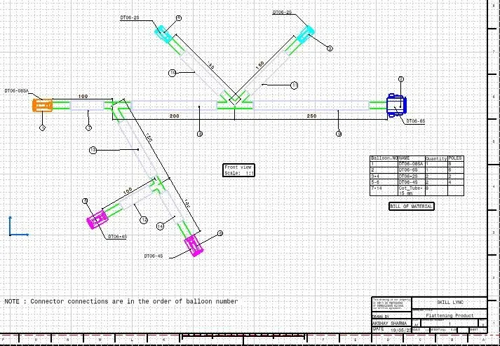
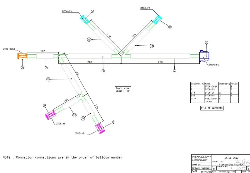
to differentiate between the wiring harness and the corrugated tube we use the green color for the wiring harness and the grey color for the corrugated tubes.
conclusion
hence we successfully completed our project along with the required objectives as per mention above in the question.