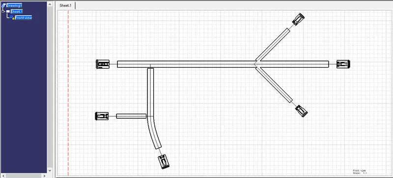
Wiring harness design in CATIA V5 - 3D modeling Week 7 Challenge
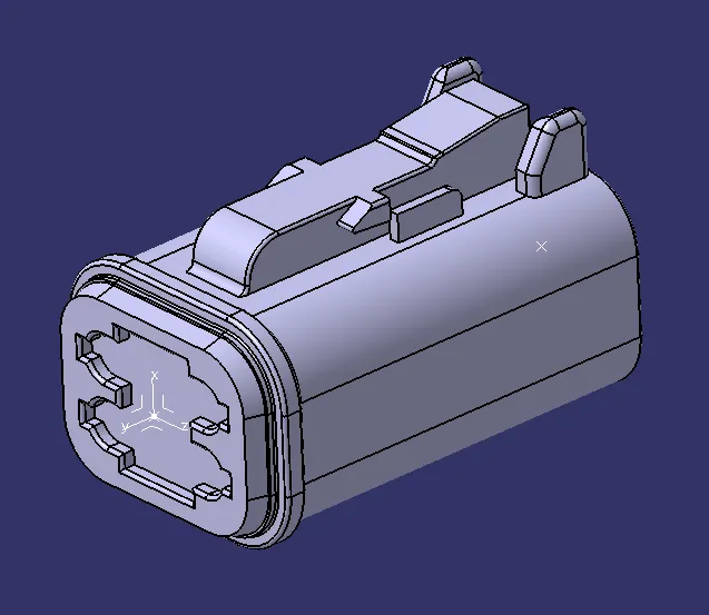
1.DT06-4S
- The 3D model is downloaded from the given link and saved as a Catpart file.
- The bundle entry Point is created at the rear part of the connector.
- The connector Point is created at the mating side of the connector.
- The connector axis is created with respect to Connector Point.
- The component is defined as the connector using "Define Connector" tab in the "Electrical Part Workbench". The number of terminals is defined.
- The bundle connection point is defined using "Bundle Connection Point Definition" tab in the "Electrical Part Workbench". The parameters are defined appropriately.
- The connector connection point is defined using "Connector Connection Point Definition" tab in the "Electrical Part Workbench". The parameters are defined appropriately
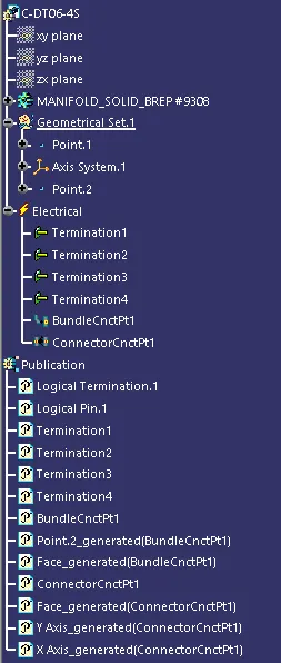
TREE STRUCTURE
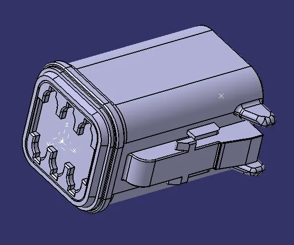
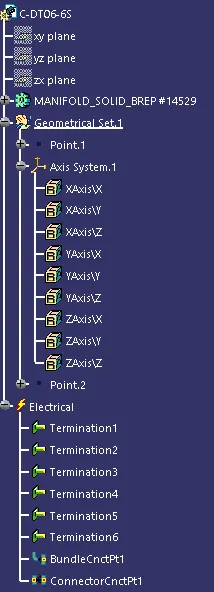
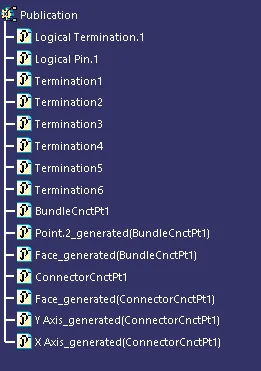
2.DT06-6S
- The 3D model is downloaded from the given link and saved as a Catpart file.
- The bundle entry Point is created at the rear part of the connector.
- The connector Point is created at the mating side of the connector.
- The connector axis is created with respect to Connector Point.
- The component is defined as the connector using "Define Connector" tab in the "Electrical Part Workbench". The number of terminals is defined.
- The bundle connection point is defined using "Bundle Connection Point Definition" tab in the "Electrical Part Workbench". The parameters are defined appropriately.
- The connector connection point is defined using "Connector Connection Point Definition" tab in the "Electrical Part Workbench". The parameters are defined appropriately
TREE STRUCTURE
3.DT06-2S
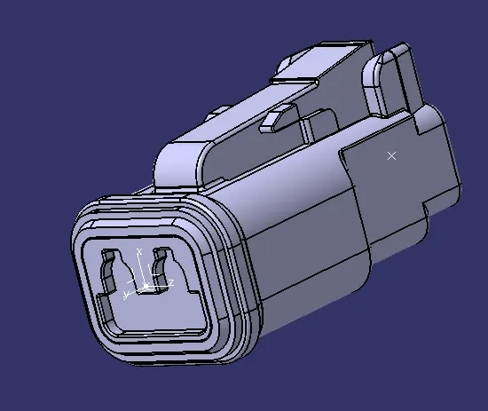
- The 3D model is downloaded from the given link and saved as a Catpart file.
- The bundle entry Point is created at the rear part of the connector.
- The connector Point is created at the mating side of the connector.
- The connector axis is created with respect to Connector Point.
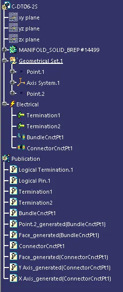
- The component is defined as the connector using "Define Connector" tab in the "Electrical Part Workbench". The number of terminals is defined.
- The bundle connection point is defined using "Bundle Connection Point Definition" tab in the "Electrical Part Workbench". The parameters are defined appropriately.
- The connector connection point is defined using "Connector Connection Point Definition" tab in the "Electrical Part Workbench". The parameters are defined appropriately
TREE STRUCTURE
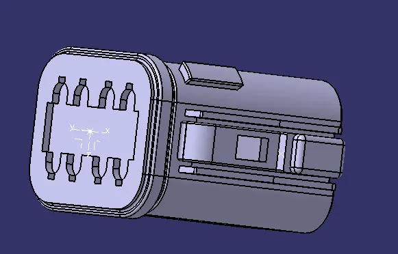
4.DT06-08SA
- The 3D model is downloaded from the given link and saved as a Catpart file.
- The bundle entry Point is created at the rear part of the connector.
- The connector Point is created at the mating side of the connector.
- The connector axis is created with respect to Connector Point.
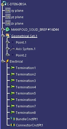
- The component is defined as the connector using "Define Connector" tab in the "Electrical Part Workbench". The number of terminals is defined.
- The bundle connection point is defined using "Bundle Connection Point Definition" tab in the "Electrical Part Workbench". The parameters are defined appropriately.
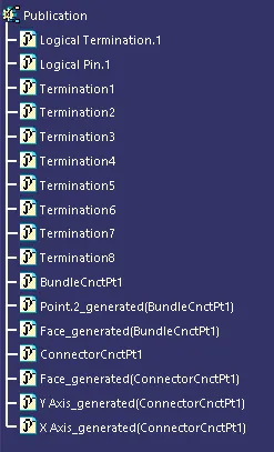
- The connector connection point is defined using "Connector Connection Point Definition" tab in the "Electrical Part Workbench". The parameters are defined appropriately
TREE STRUCTURE
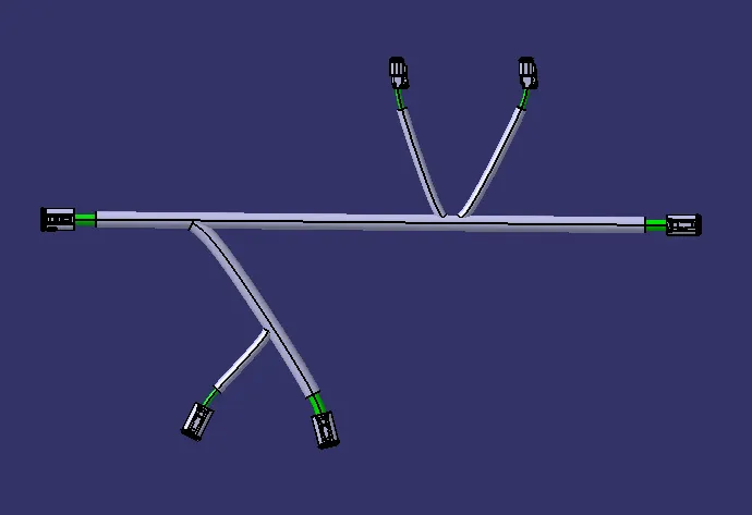
Assy_Wiring_harness
TREE STRUCTURE
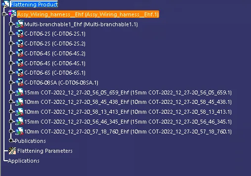
Electrical Harness Flattening:
- Now select File> New> Product> Electrical harness flattening and save
- Now in order to use the enable the other options first we need to decide the "Harness flattening parameters" and define them
- Now select option "Extract" and arrange the windows vertically and select the geometrial bundle so that the component will be inserted
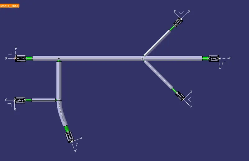
- Now select the flatten option choose the plane and select the brances and click ok
- After clicking ok _Ehf(electrical harness flattening) is applied to the geometrical bundle name
- Now we can manipulate the bundle by using rotate, roll, straighten, bend and arrange junction options according to our requirement
TREE STRUCTURE
DRAWING:
- Now click File> New>Drawing and slecet format and click ok.
- Save and now select front view and go to the flattening and selct the top plane of the connector and the drawing file is created now arrange it with the required angle and select any where on the drawing
- Now right click and go to proporties and go to view and select the following properties like 3D wireframe and apply and click ok
- So now we have created the drawing file