Wiring harness design in CATIA V5 - 3D modeling Week 7 Challenge
Task: Flattening The Assembly and Create 2D Layout
Objective:
- To flatten the wire harness assembly completed in week 4 assignment.
- To orient the wire bundle as shown in the layout.
- To place the flattened view on a drawing sheet.
- To ensure bundles with protective coverings has different visuals on drawing view.
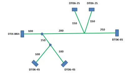
Construction Of Model:
Step 1:
- Create a product file and navigate to the Electrical Harness Flattening for wire harness flattening option and save it in the same location where the wire harness or routing assembly is stored.
- Define the 'Harness flattening parameters' in order to flatten the required wire harness assembly.
- While defining the harness flattening parameters in the drawing menu single line is selected for bundle segment and double line is selected for protective coverings in order to differentiate between the wire bundle and cot tubes in drafting.
Step 2:
- Select the 'Extract' option from the Electrical Harness flattening workbench and select the Geometric bundle product in the wire harness assembly product file.
- Then wire harness assembly is imported to the Wire flattening product file with 'EHF' extension added to the geometric bundle assembly name.
Step 3:
- Select the 'Flatten' option to flatten the wire harness assembly.
- Then select the active plane, then select any one branch and then select the 'select all branches'.
- If there is no discontinuity in the bundle segment then all the branches will be selected and by pressing 'ok' the wire harness assembly will be flattened.
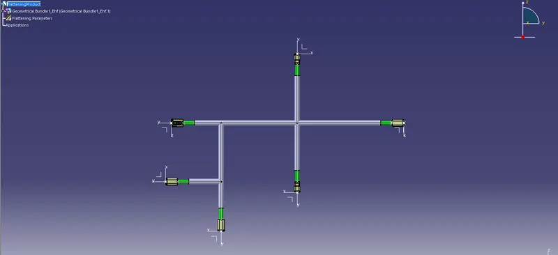
Step 4:
Use 'Rotate' and other commands to rotate the branches and bring them in proper orientation as per the given layout.
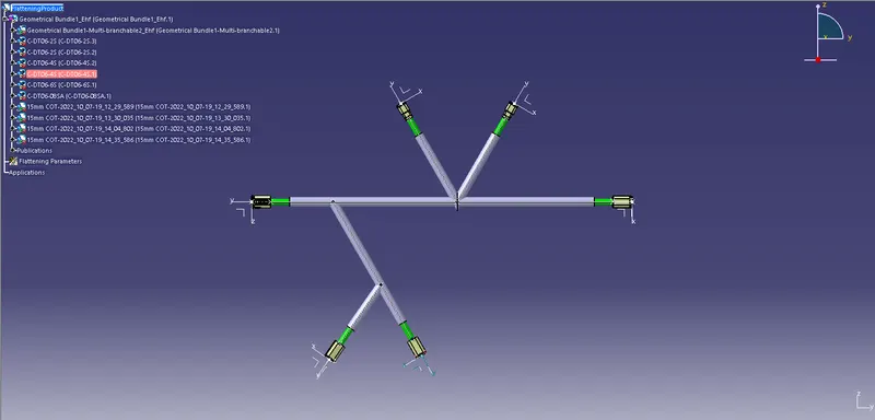
Step 5:
Creating the 2D drawing of the Flattened Assembly also Mention Title Blocks and the Bill of Material in the Drawing Sheet.
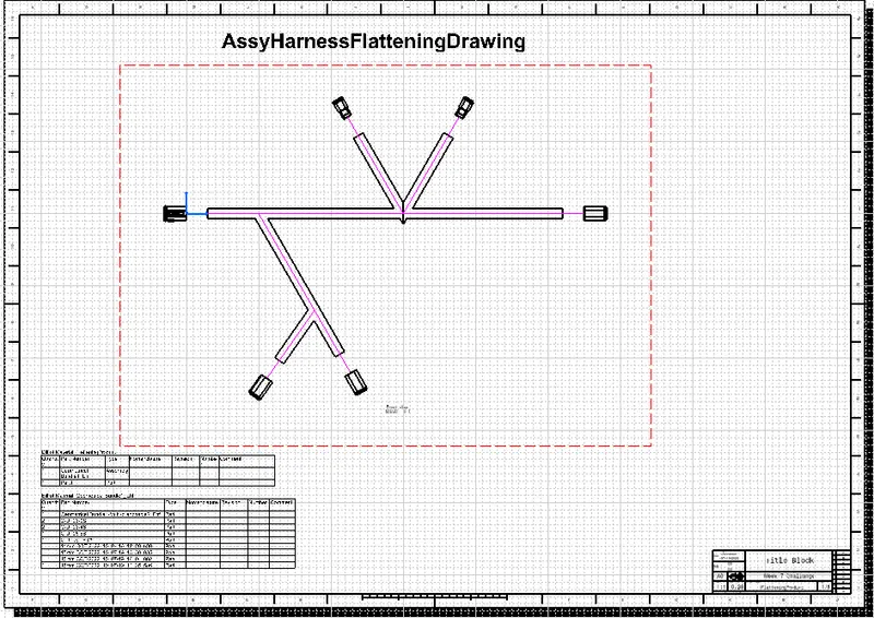
Conclusion:
Thus, 2D Drawing of the Flattened Assembly is Created and it is Ready to Release for Proto Development.