Wiring harness design in CATIA V5 - 3D modeling Week 7 Challenge
DT06-2S
First imported models from given link. open mechanical part design.
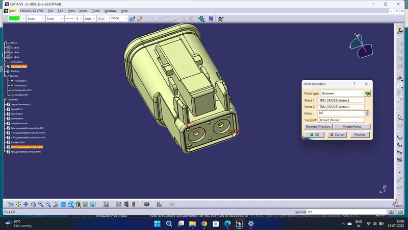
Defined the middle point with help of the mid-point. On the connector side and bundle side.
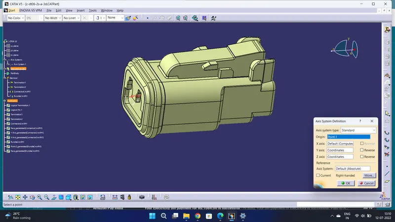
Given axis system to connector side.
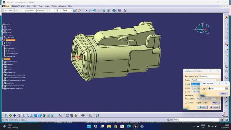
Rotated x-axis 90 degrees for y-axis coincidence.
Now changing the workbench electrical part design.
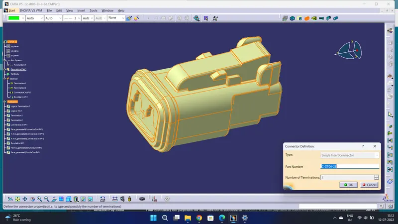
Defined as a connector with 2 terminations.
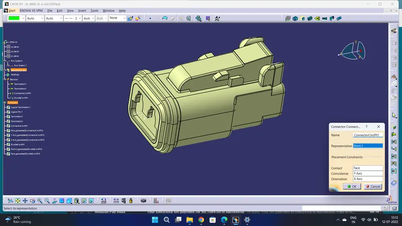
Then Defined the connector side as the connector connection point.
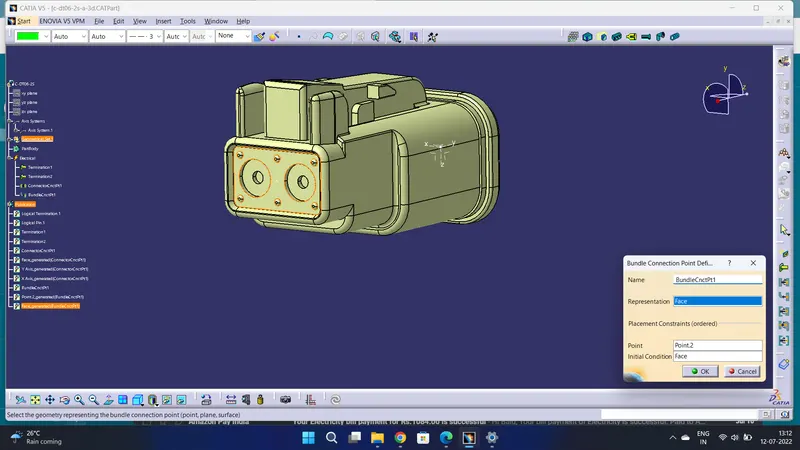
Defined bundle connection side as a bundle connection point.
DT06-4S
First imported models from given link. open mechanical part design.
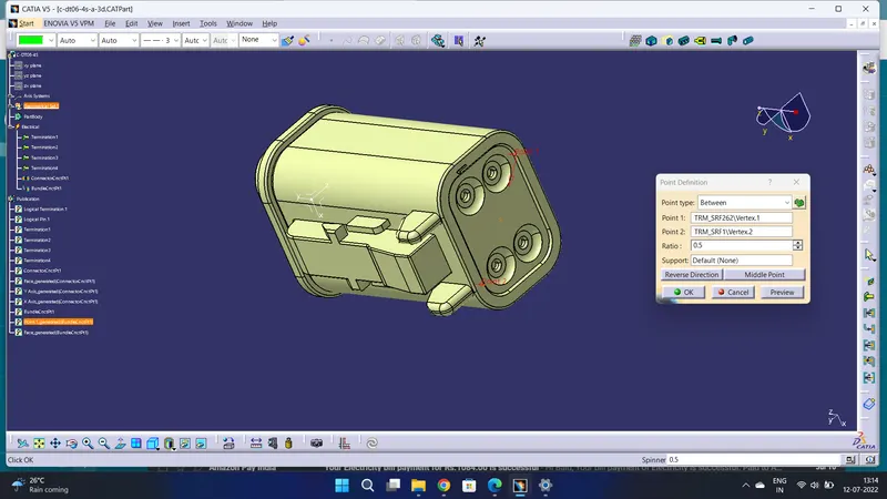
Defined the middle point with help of the mid-point. On the connector side and bundle side.
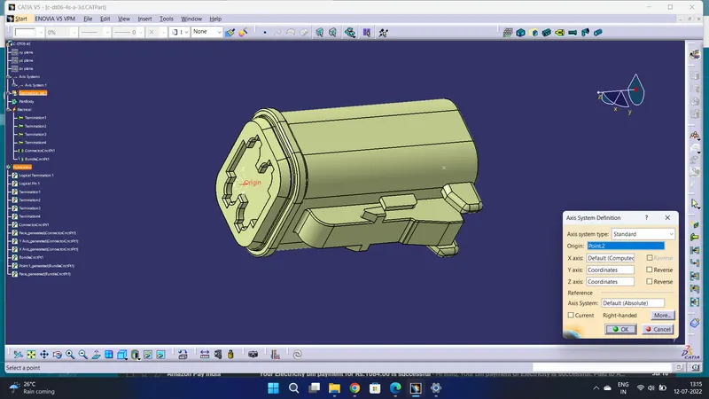
Given axis system to connector side.
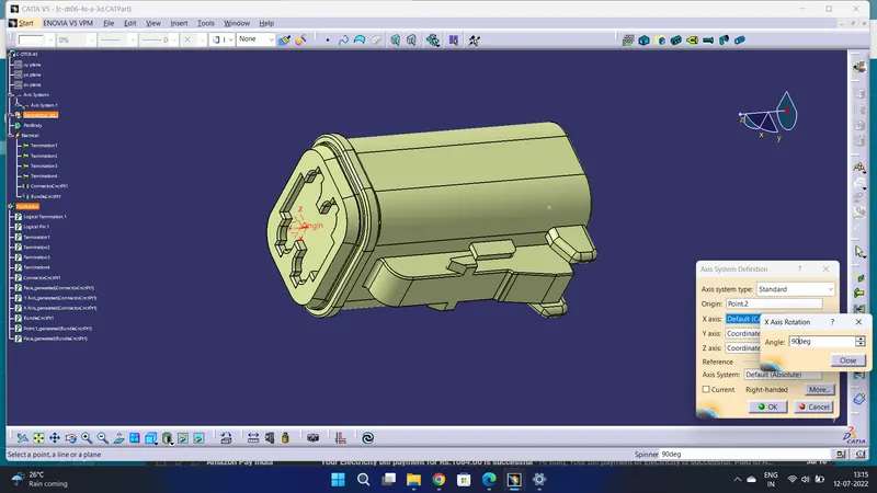
Rotated x-axis 90 degrees for y-axis coincidence.
Now changing the workbench electrical part design.
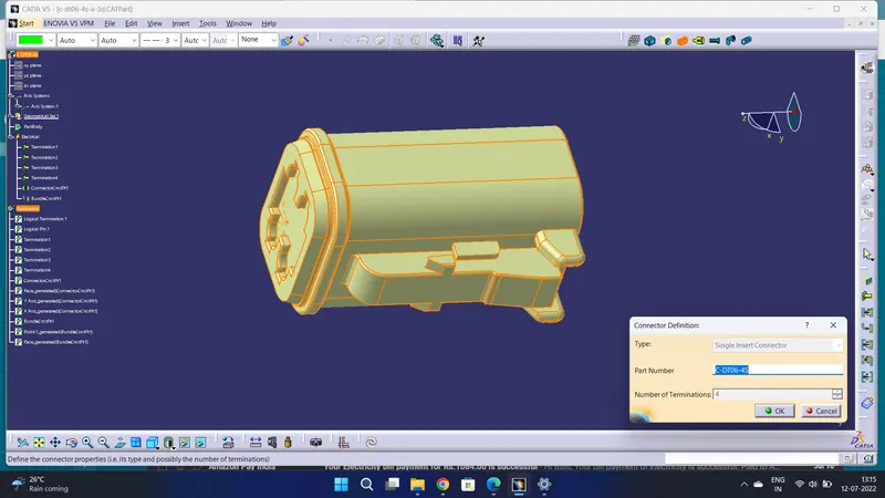
Defined as a connector with 4 terminations.
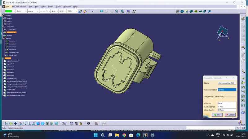
Then Defined the connector side as the connector connection point.
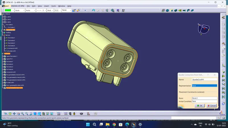
Defined bundle connection side as a bundle connection point.
DT06-6S
First imported models from given link. open mechanical part design.
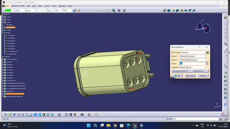
Defined the middle point with help of the mid point. On the connector side and bundle side.
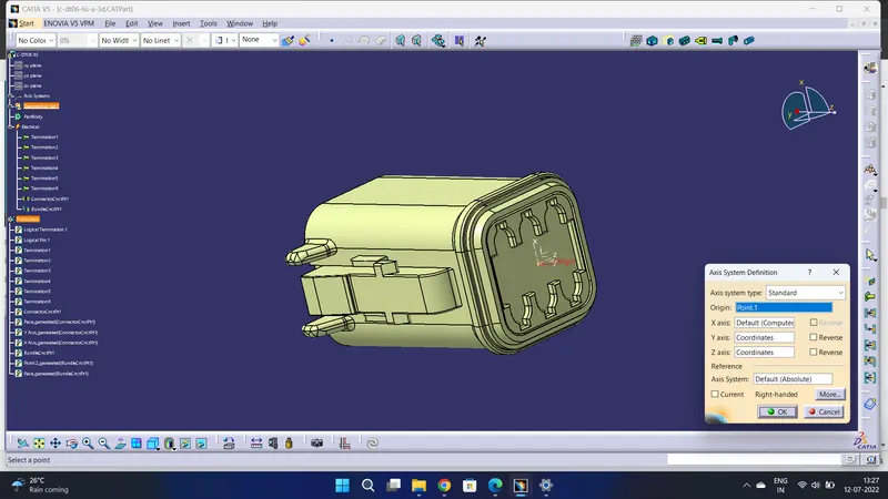
Given axis system to connector side.
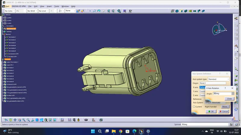
Rotated x-axis 90 degrees for y-axis coincidence.
Now changing the workbench electrical part design.
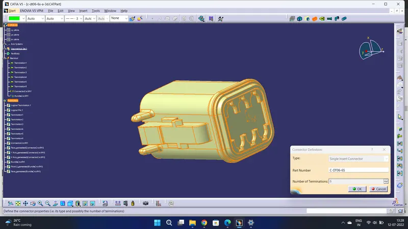
Defined as a connector with 6 terminations.
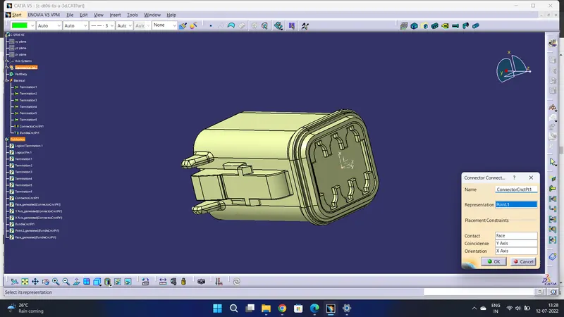
Then Defined the connector side as the connector connection point.
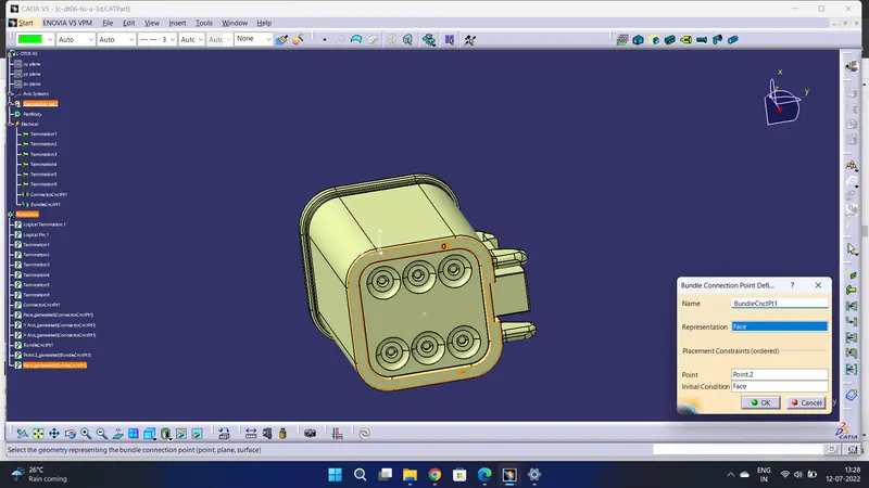
Defined bundle connection side as a bundle connection point.
DT06-08SA
First imported models from given link. open mechanical part design.
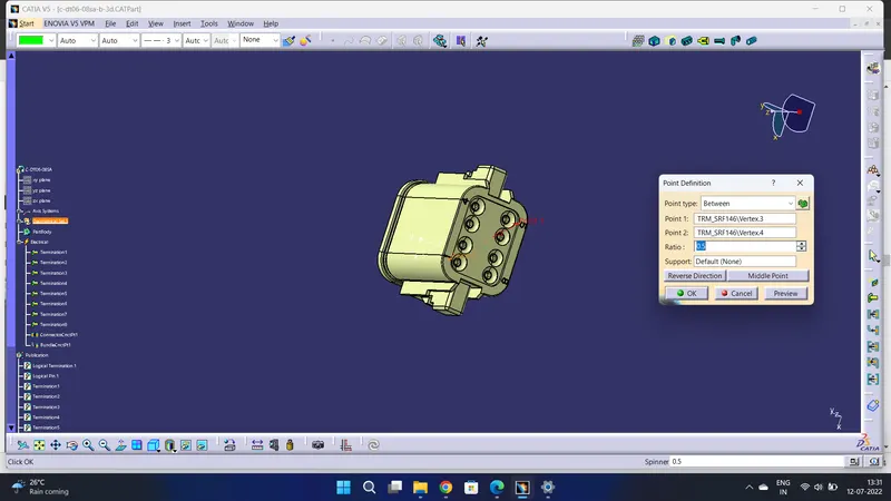
Defined the middle point with help of the mid-point. On the connector side and bundle side.
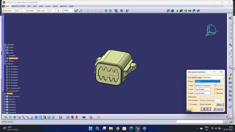
Given axis system to connector side.
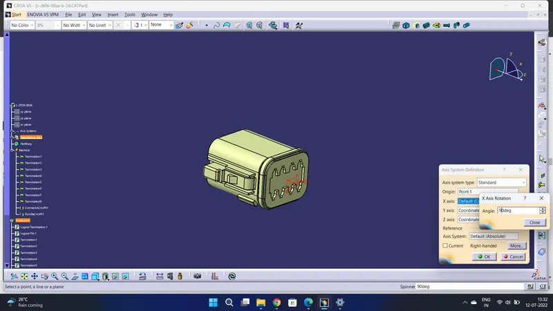
Rotated x-axis 90 degrees for y-axis coincidence.
Now changing the workbench electrical part design.
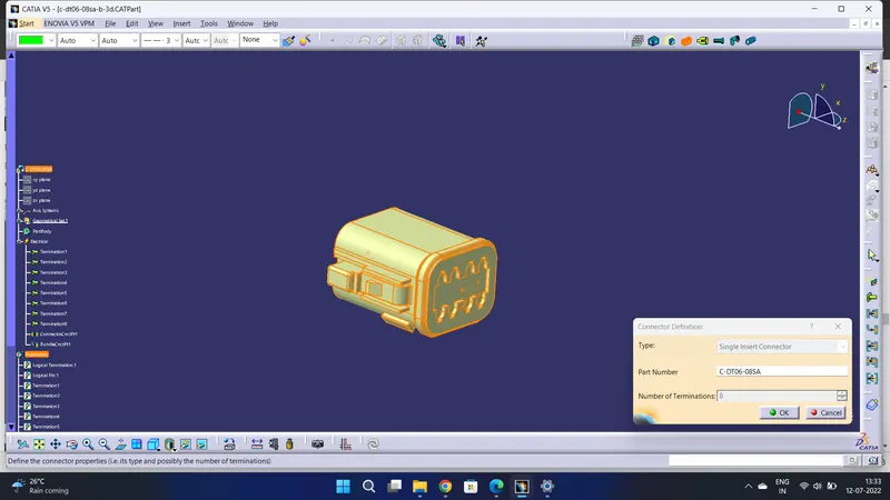
Defined as a connector with 8 terminations.
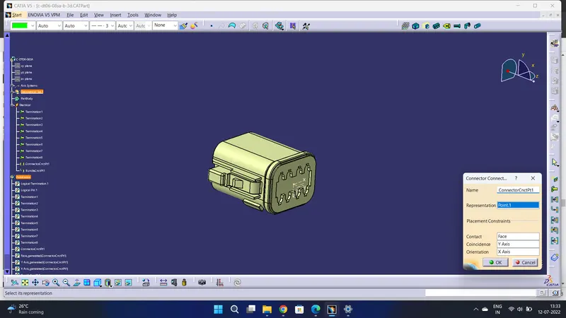
Then Defined the connector side as the connector connection point.
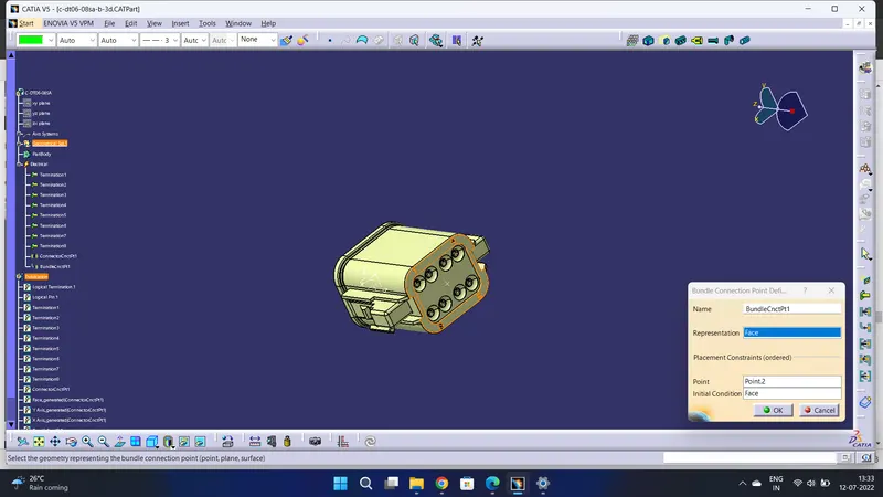
Defined bundle connection side as a bundle connection point.
Product
Open a new product file and imported all the defined models into it.
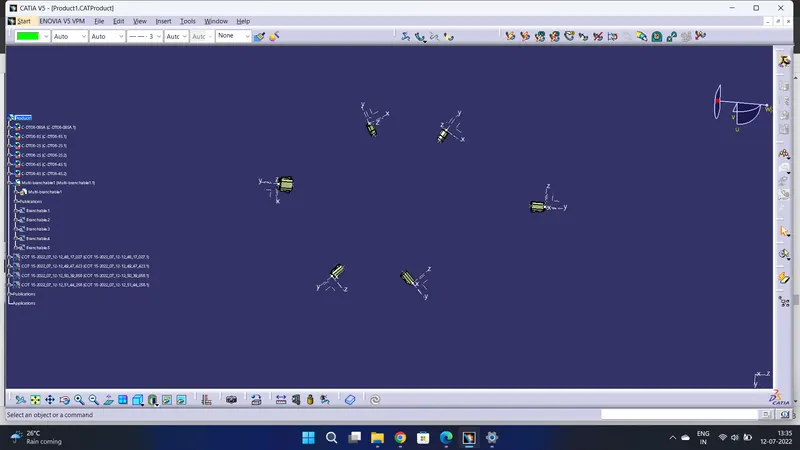
Manipulated all the models into the required positions.
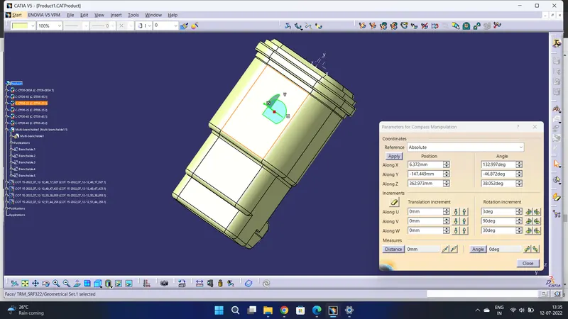
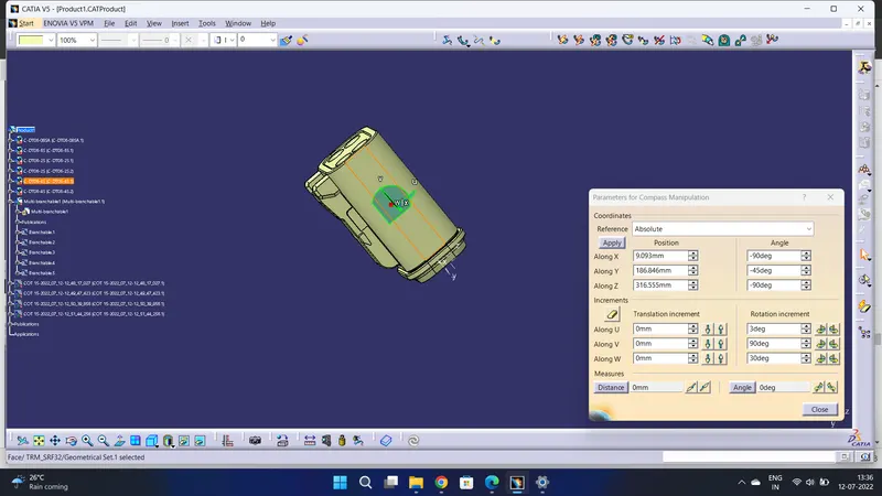
Rotated all the connectors as required.
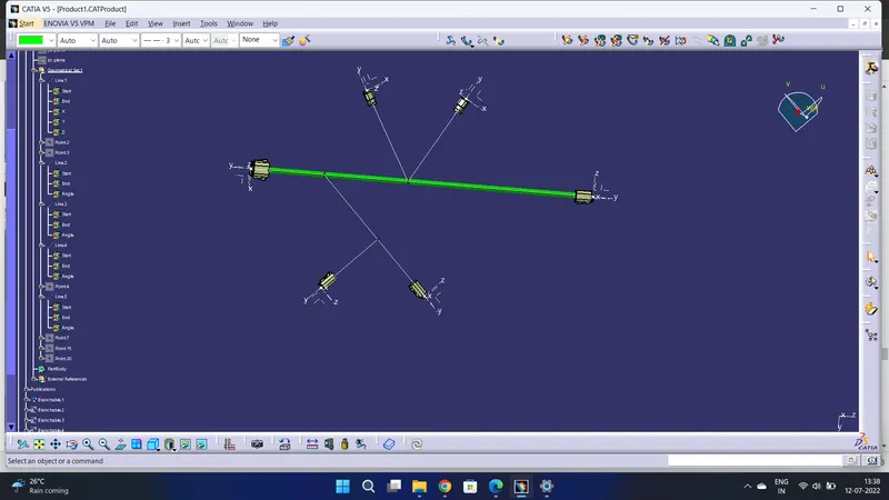
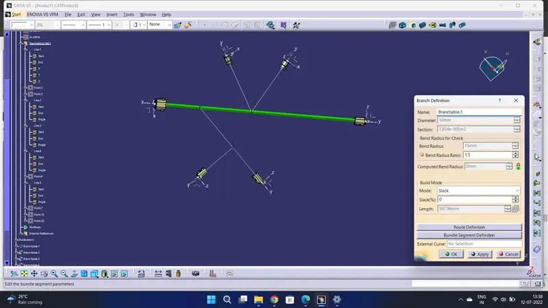
Made the main branch Bundle to bundle.
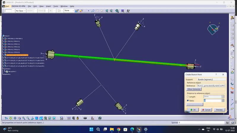
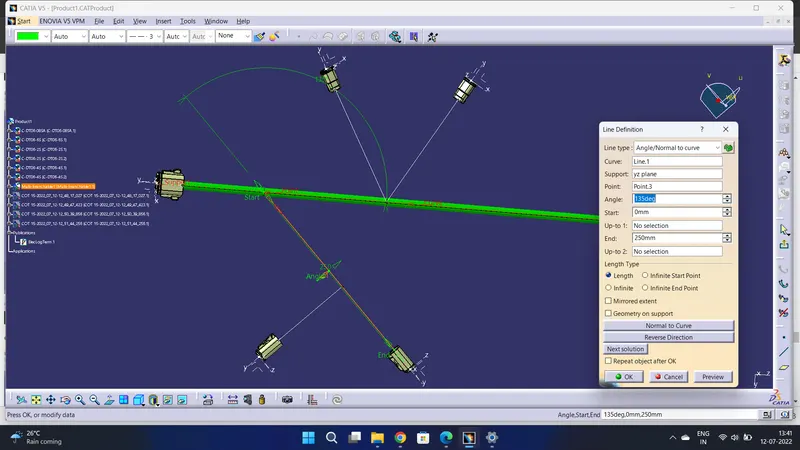
Create a Branch point with a distance of 100mm. with that point made a line with help of a point to direction.
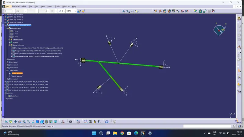
created branch with help of line.
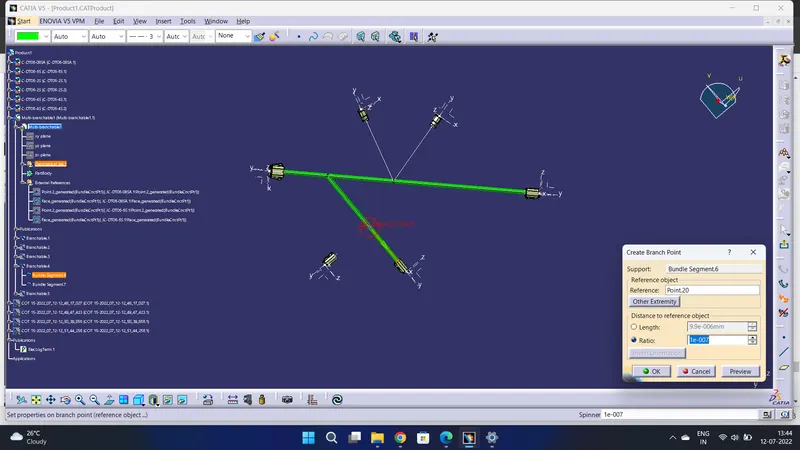
Now created Branch point distance of 100mm for sub branch.

A created line from the branch point with a direction of the connector y-axis.
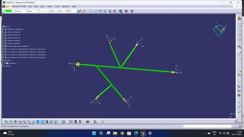
all the branches are created with lines.
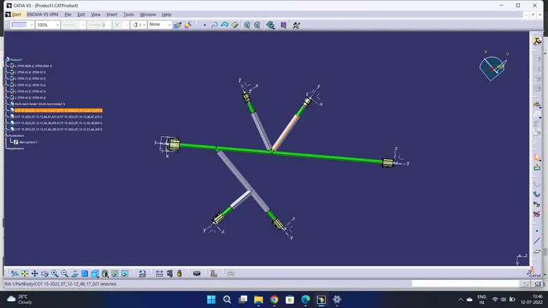
Made Cot for all sub-branches by maintaining a 30mm distance from the connector side.
Then Opened a new product file in Electrical wiring Harness Flattening.
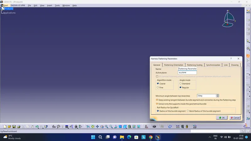
Harness Flattening parameters Changes made as required.
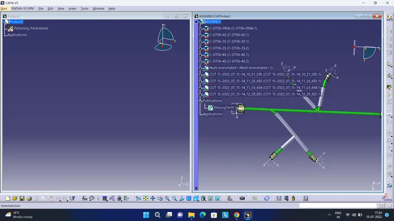
Now imported file by using extract.
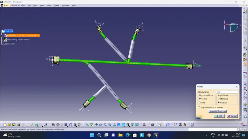
Now done Flatten By selecting the connector face as an active plane and selecting all branches.
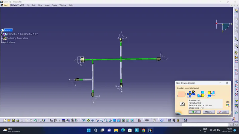
For Converting to drawing file opened new drawing file.
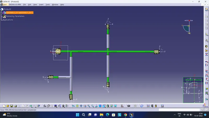
The connector face is selected as the front view.
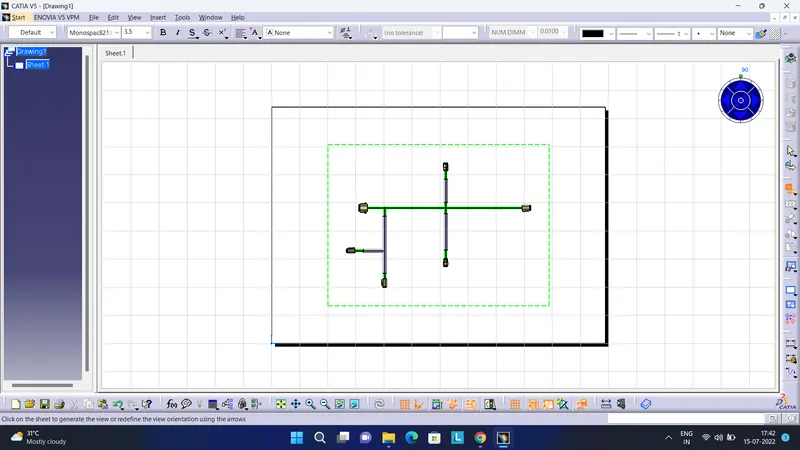
Imported the product to the drawing file.
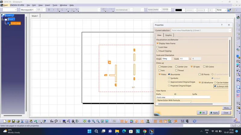
Made changes in properties for branches visualization.
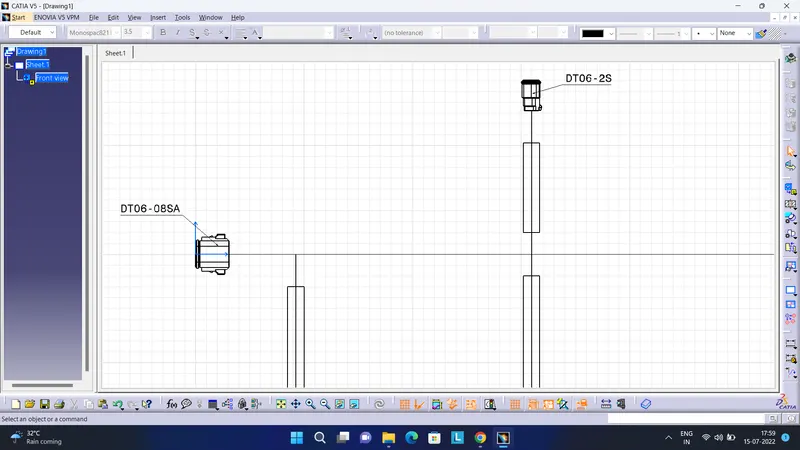
Given identification numbers to all the connectors.
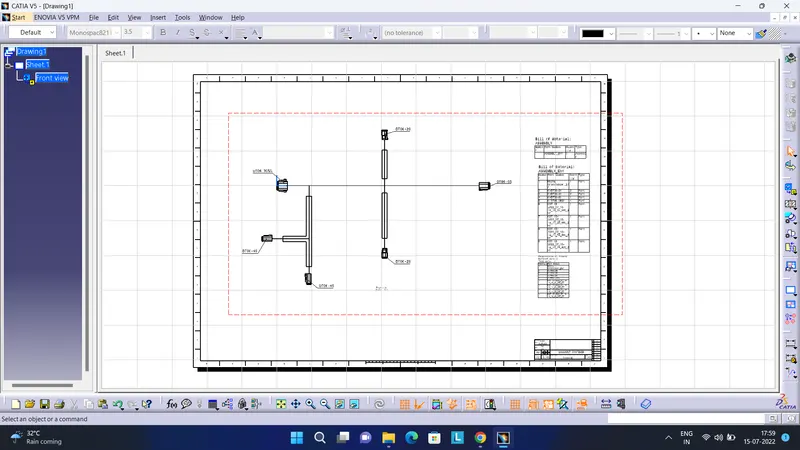
Then I made a bill of material and title block.