Wiring harness design in CATIA V5 - 3D modeling Week 5 & 6 Challenge
Wiring harness design and Routing
Wire harnesses are a mixture of wires that are bundled together to form a wire harness. Wire harnesses range in complexity from a few individual wires going point to point to hundreds of individual wires, multi conductor cables and welded wires all forming a complex wire harness used to transmit power and all types of data. Wire harness designs are highly customizable, as harnesses are typically designed to suit specific applications. They may need to be concealed behind walls, fit within electrical boxes, or conform to other space constraints. Precise measurements of the environment, power demand, and lengths must be taken during design to prevent costly mistakes and ensure proper safety and functionality of the final product.
A wiring harness routing structure includes a wiring harness routing member configured to be attached to a vehicle body and a protector that accommodates and holds a wiring harness. The protector has a recess shape in which the protector is opened in one direction in a sectional view. At least one of the wiring harness routing members and the protector includes a fixing mechanism that fixes the protector to the wiring harness routing member. The protector and the wiring harness routing member are configured to be integrated via the fixing mechanism.
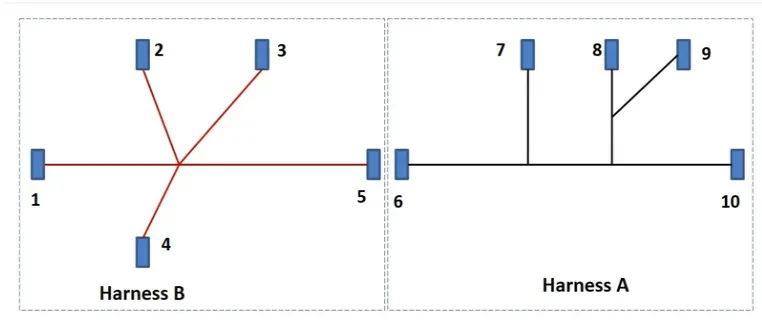
Given Harness Input
Flow chart to create Harness Design
- Download the neutral data file (step file / igs file) of the connectors from the given source (TE connectivity website) and open it in the CATIA part workbench.
- Identify the faces of the connector connection point, bundle connection point and the mechanically locking sides of the connectors.
- Create the geometries like center points of the connector connection point and bundle connection point by selecting appropriate edges and create an axis on the connector connection point by placing the Y axis towards the connector connection point (mating point) direction and the X axis pointing towards the side of the locking mechanism. The same axis direction should be followed for the compatible mating part.
- Now switch to the electrical part design workbench and define the model as an electrical connector part by using the define connector command.
- Define the connector connection point by giving the representation as the back connector connection point, selecting the face of contact, coincidence direction as Y axis and orientation direction as X axis.
- By using the define bundle connection point command select the face of the bundle entry side and the bundle center point to define the bundle connection point of the connector.
- Now the connector part file is converted into the electrical part file with all electrical properties.
- Follow the same steps for converting all connectors into electrical.
Create new product file for wiring harness assembly, adding the relevant components to each product file and convert the geometrical bundle assembly file into an electrical bundle
- First create the main product file for the wiring harness assembly and then create the new product files for geometrical bundle assembly and electrical bundle circuit.
- Open the geometrical bundle assembly in a new window and switch to the mechanical assembly workbench and add all the relevant connectors required for the harness assembly routing.
- Position the connectors to the desired location by using various commands available in the mechanical assembly workbench.
- Switch to the electrical harness assembly workbench and activate the geometrical bundle command and select the geometrical bundle assembly file from the tree structure then it will convert the geometrical bundle assembly file into an electrical assembly file.
Applying routing to the wiring harness assembly
- By using the multi-branchable document command available in the electrical harness assembly workbench and adjust the options available likes, connector diameter, bend radius ratio, build mode, and with the help of routing objects options define the routing by adding the desired connectors and adjust the tangency if required to get the proper bundle connection between connectors.
- It is always recommended to use multi-branch routing during the wiring harness assembly.
- We can add branches or split the existing branches by double-clicking the multi-branch-able command then it will automatically switch into the wiring harness installation workbench from there we can add a branch point on the existing bundle to the required position.
- Again go to the multi branch-able document command and select the appropriate connectors and bundles to create sub-branches in the assembly.
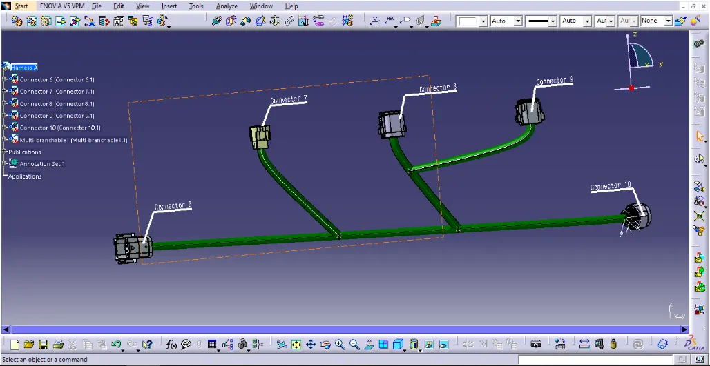
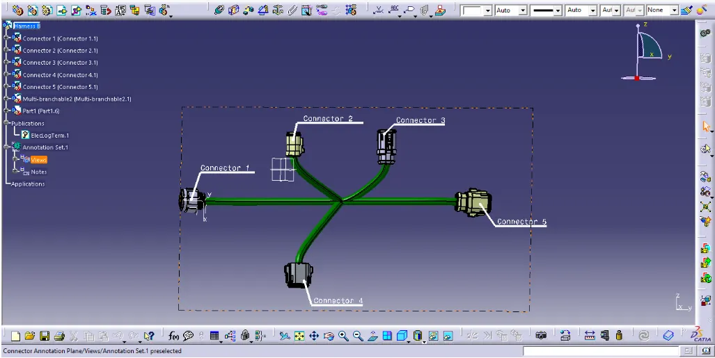
- Follow the same steps for creating product files of A & B.
Harness A
Harness B
1) Check for the bundle continuity in the wiring harness assembly
- Under the edit command select the search icon (binocular symbol) a pop-up window will appear to select the advanced option and arrange the options available by selecting, workbench as electrical, type as bundle segment and attribute as fully connected.
- A pop-up window will appear, while selecting it as false and selecting the search button it will show all the discontinued bundles in the assembly. If we select it as true, it will show a fully interconnected bundle throughout the assembly.
- By taking the result we can adjust the routing and make it fully connected bundle set.
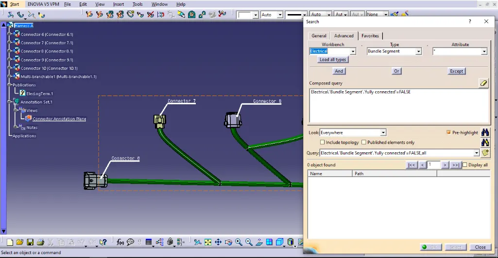
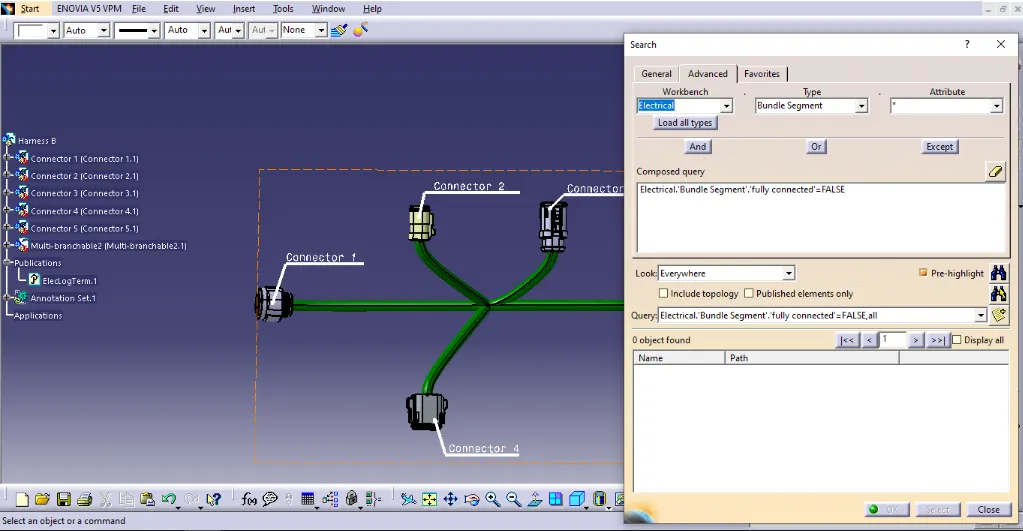
All harness are connected properly with each other.
2) Adding the annotations to the wiring harness assembly
- For adding annotations to the assembly we have to switch into the mechanical assembly workbench and first define the plane by selecting view from reference command and in the pop-up window select the type as projection view.
- Then give the notes or functional command to the assembly by using various options available such as flag note with header, flag, etc.
- We can add multiple reference notes on the same object using the same or different planes.
- Also we can use single planes for different planes to add notes for all the elements in the assembly.
3) Check for bundle warnings and resolve the error
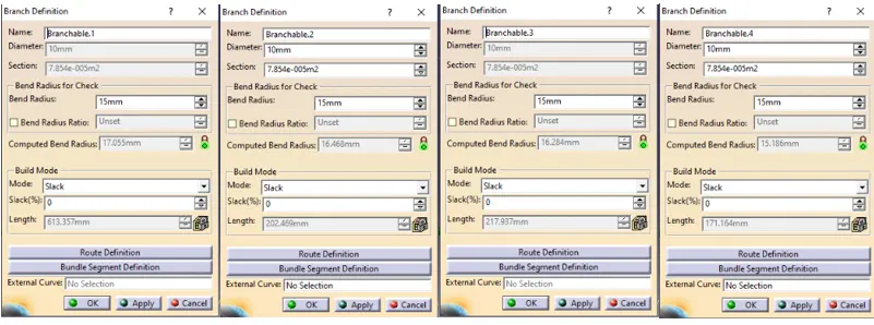
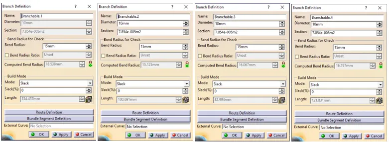
- Bundle warnings are mainly due to the inappropriate bend radius given to the bundle this can be solved by adjusting the position of connectors, adjusting the bundle break point for sub-branches, reversing the tangency of the bundle, adding extra slag, etc.
- It is recommended to maintain the tentative bend radius always less than that of the computed bend radius of bundles.
No error is shown.
For Harness A
For Harness B
Connecting the two sets of wiring harness assembly
- Create a new product file and add the two sets of wiring harness assemblies A & B.
- Check for the position and mating face of connectors if any modification needs to be done can be carried out by opening the required assembly in the new windows and returning to the product file.
- Switch to the electrical assembly design workbench and by using the connect electrical device command select the appropriate mating compatible parts of the connector. Thus both assemblies joined together and form a single assembly.
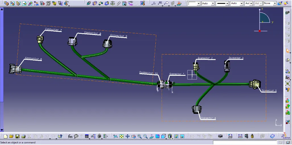
4) Create CAT part of harness assembly and convert it into a neutral data file (. igs format.)
- Neutral CAD file formats are universal files that can be interoperable between different CAD software. Neutral file formats were developed to make it easier to exchange files with someone that is using different CAD software.
- In the CATIA V5 cad tool we can convert the CAT part by switching to the mechanical assembly workbench by selecting CAT part from product under tools command.
- This can be converted into a neutral file (igs) by selecting igs format in the save as command.