Wiring harness design in CATIA V5 - 3D modeling Week 5 & 6 Challenge
Wiring harness design in CATIA V5
Aim:
Route two electrical harnesses per the given layout and interconnect them as a single harness assembly
check for bundle continuity, and bundle warnings, and then provide annotations for the final harness assembly.
Objective:
The objective of this project is to first route the two Harness A and Harness B as per the given harness layout.
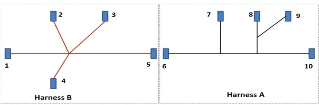
Figure 1: Shows the layout of two Harness A and Harness B
- The electrical connectors are represented by numbers in the above figure. There are 8 different types of connectors at 10 different locations.
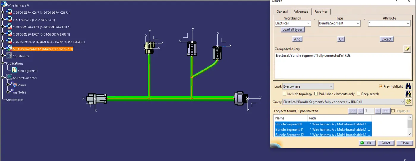
- Bundle continuity has to be checked for the two created harnesses.
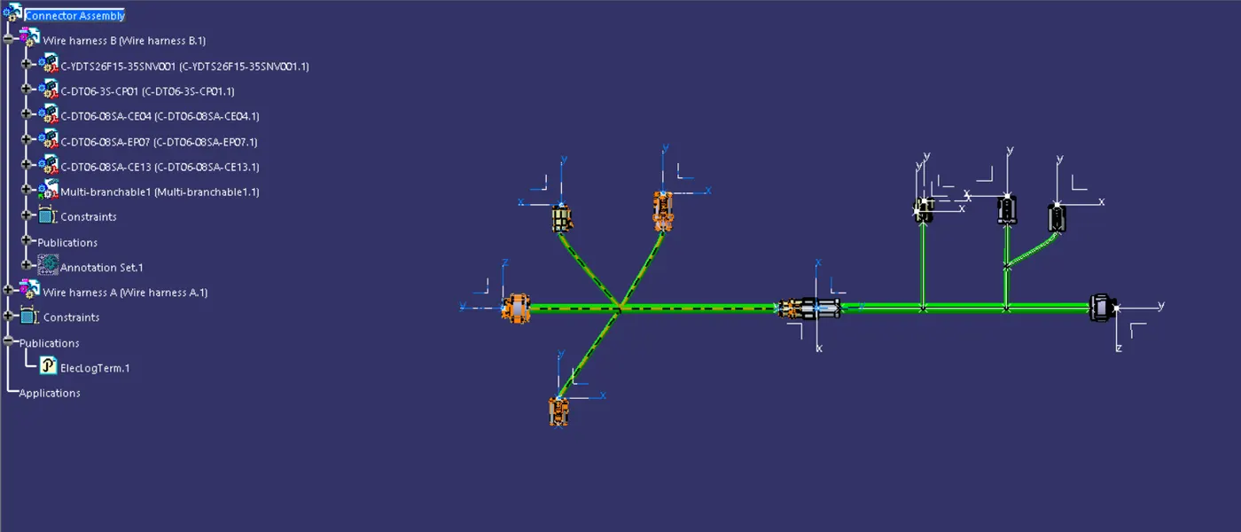
- After the two Harnesses are created, the next objective is to have them interconnected electrically.
- Check for bundle warnings in Harness A and Harness B.
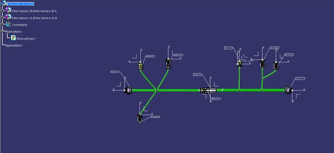
- Add annotations to all the connectors in Harness A and Harness B.
Content:
The following steps are to be done to complete this project.
Step-1:
Define all the electrical connectors geometrically and electrically so that they can be used in the wiring harness.
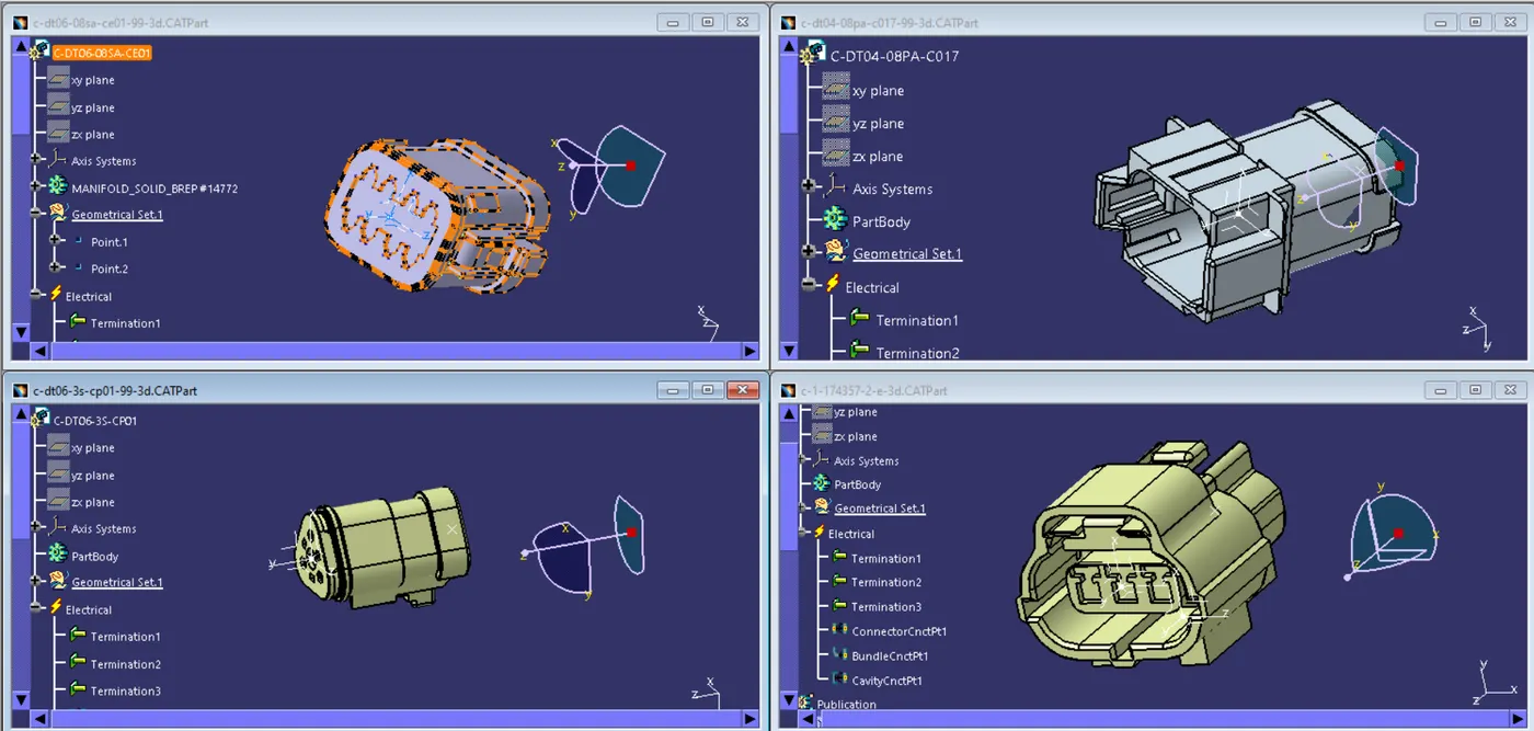
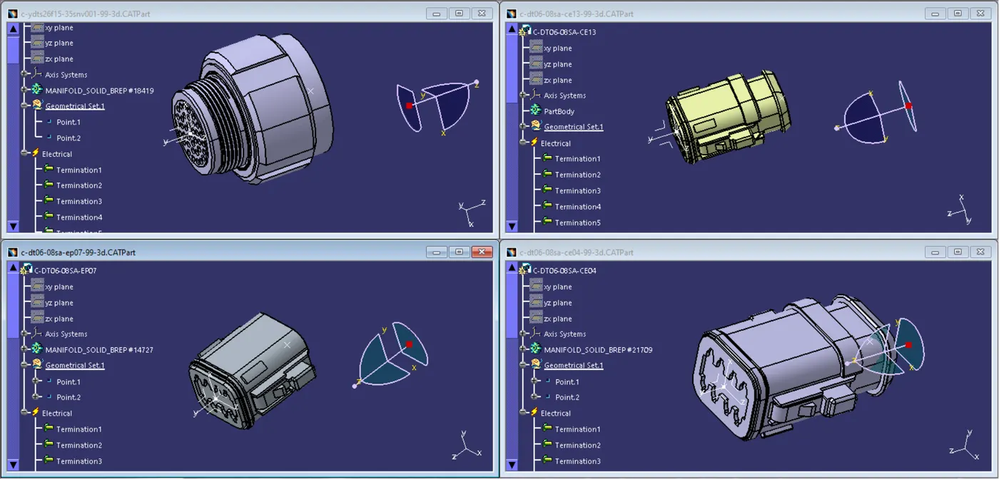
HARNESS A:
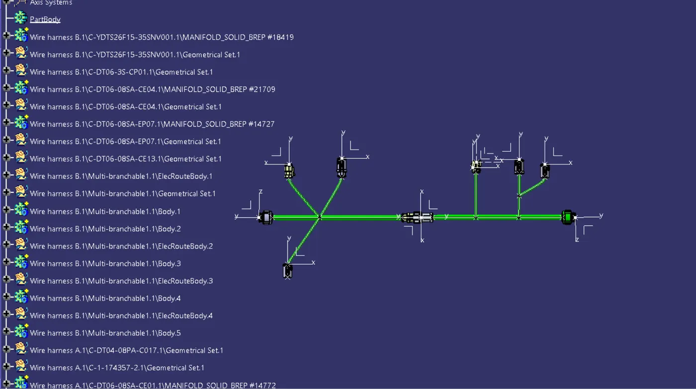
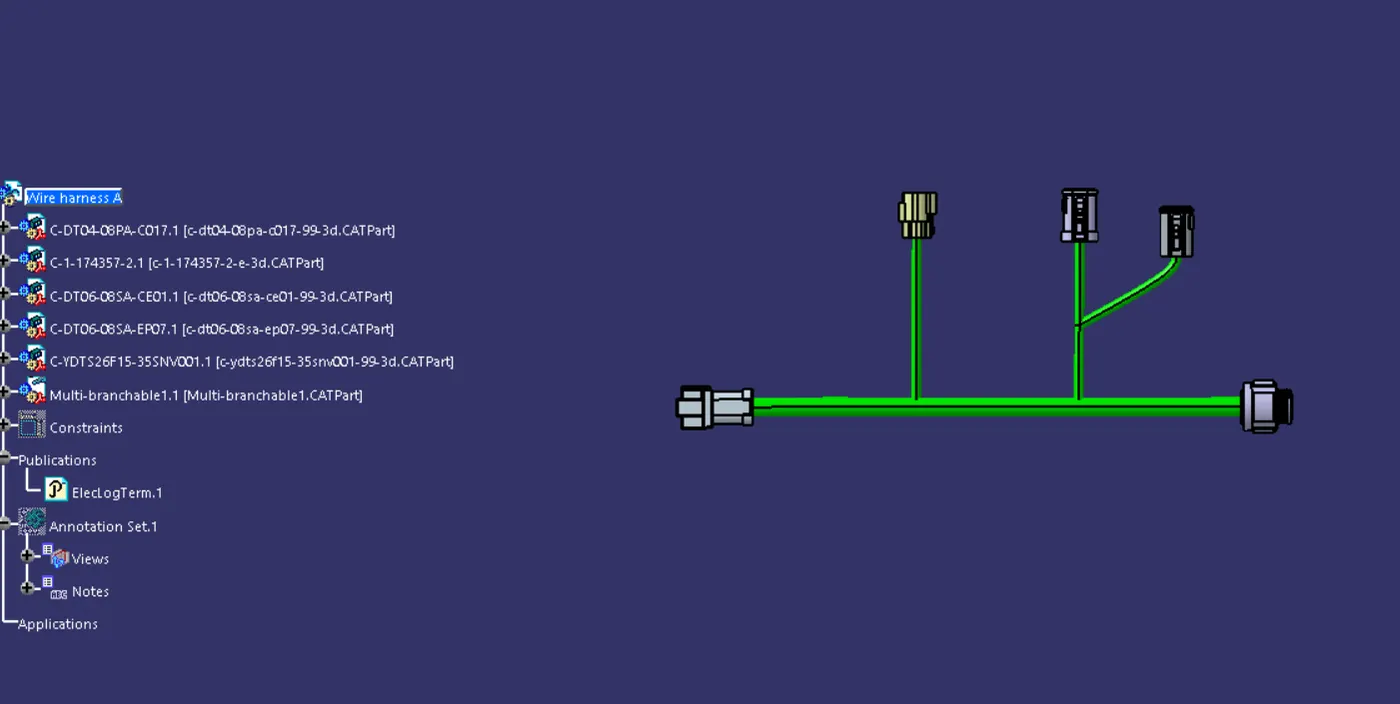
After all the connectors are defined, the workbench was switched to Electrical Harness Assembly where Geometrical Bundle was activated. All the connectors were routed using the Multi-Branchable Document command.
HARNESS B:
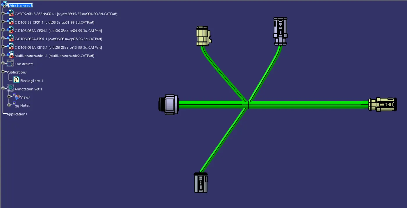
After all the connectors are defined, the workbench was switched to Electrical Harness Assembly where Geometrical Bundle was activated. All the connectors were routed using the Multi-Branchable Document command.
HARNESS ASSEMBLY
CONNECTIVITY CHECK:
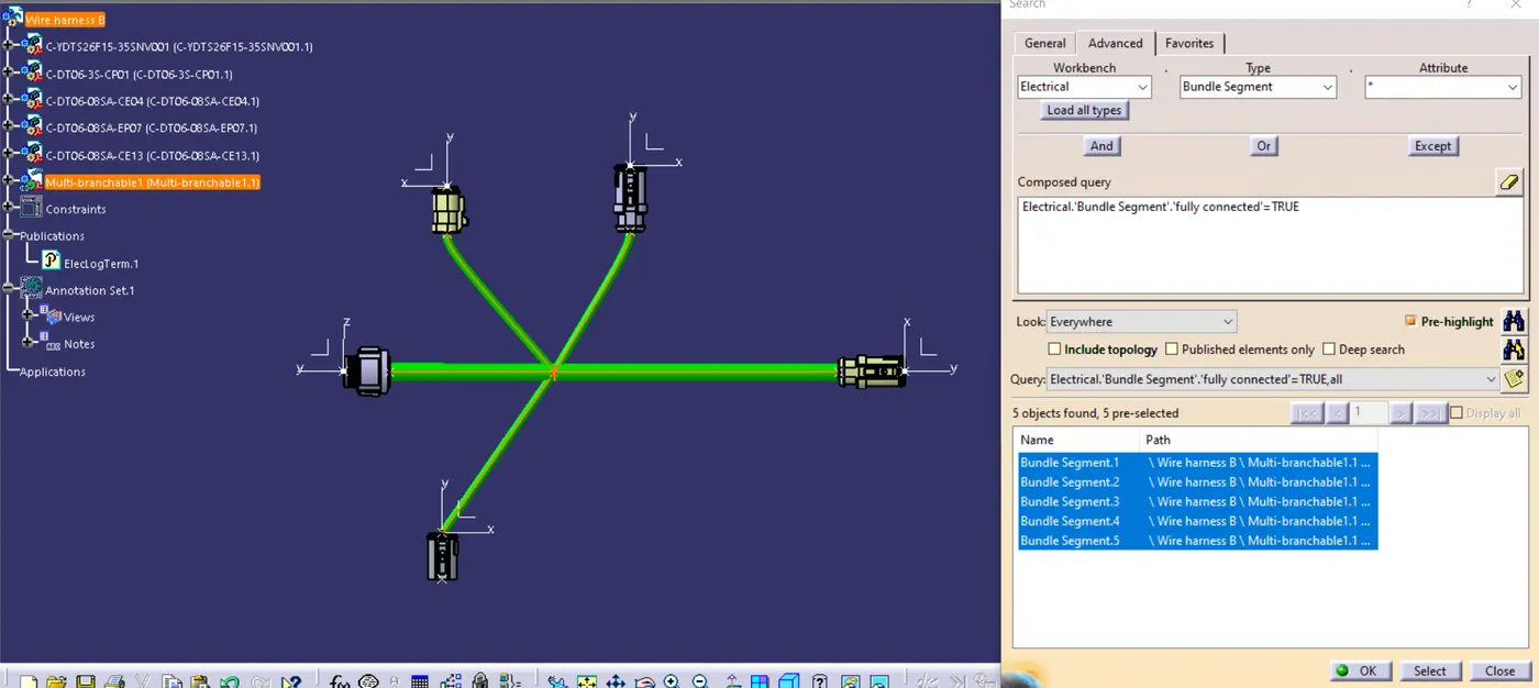
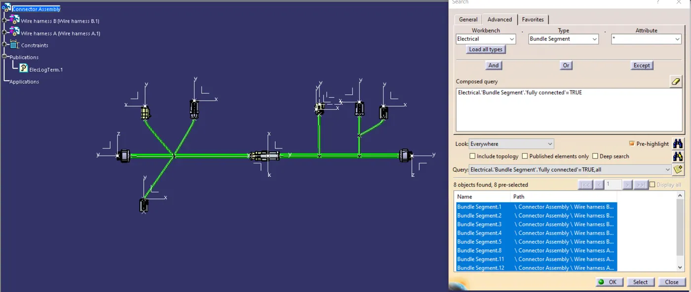
ANNOTATIONS:
Converted as a part body and save as IGS Format: