Radar Mast & Final Assembly of Yacht
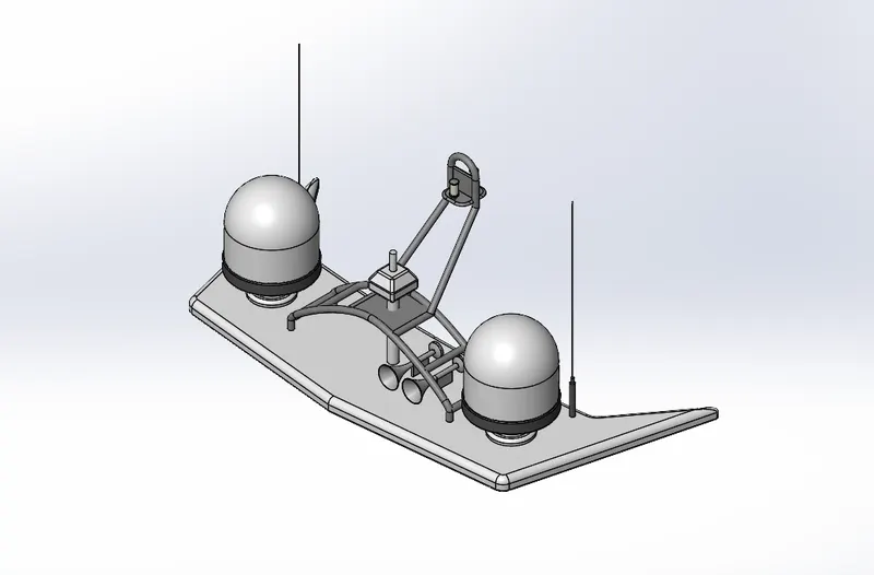
Radar Mast:
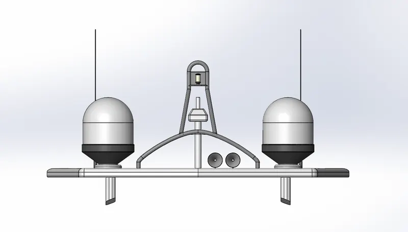
Radar Mast_Front view:
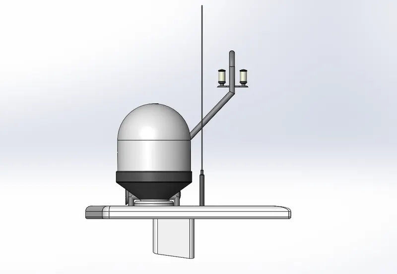
Radar Mast_Side view:
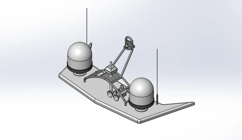
Radar Mast_Isometric view:
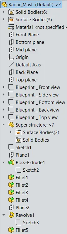
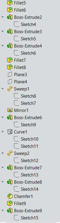
Design Tree_Radar Mast
Yatch Assembly:
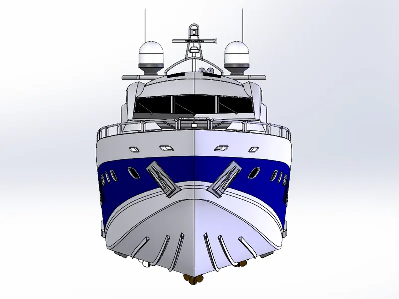
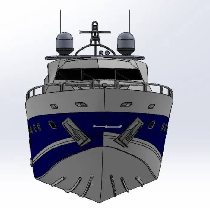
Yatch Assembly_Front view
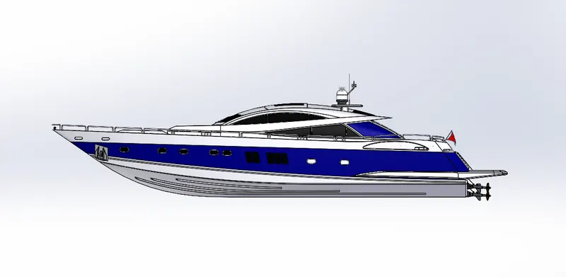
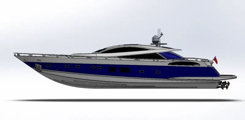
Yatch Assembly_Side view
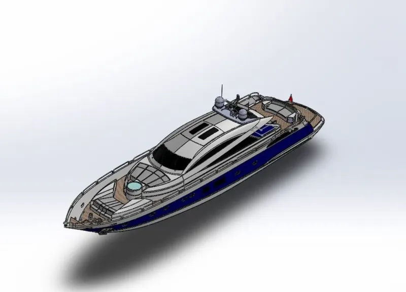
Yatch Assembly_Isometric view
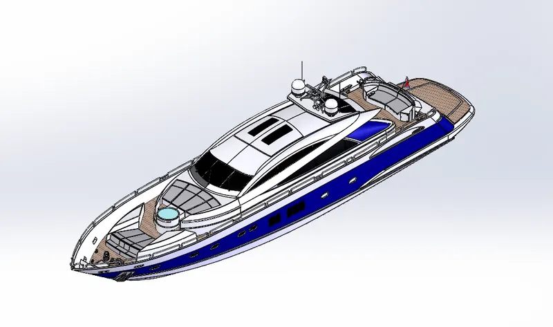
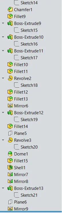
Design Tree _ Yatch Assembly
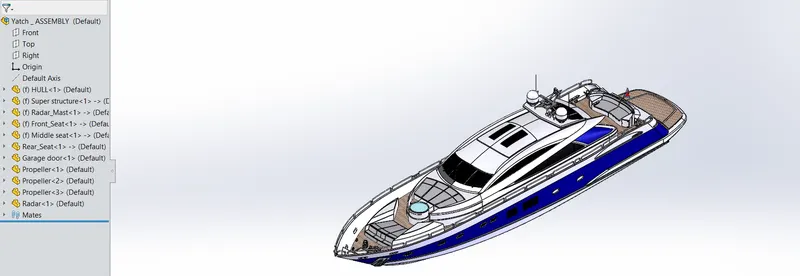
Radar Mast & Final Assembly of Yacht Report
Report on Yacht Modelling
Objective
To model a Yacht by using solidwork and assemble all the components.
Introduction
A yacht is a sailing or motor boat used for pleasure, navigation, or competition. There is no standard definition, so the term is appliedto ships that have a cabin with facilities suitable for overnight use. Unlike a boat, such a pleasure craft is likely to be at least 33 feet (10m) in length and have been found to have good aesthetic qualities.
Racing yachts are designed with an emphasis on performance over comfort. Charter yachts are run as a for-profit business.
Design methodology / approach
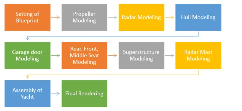
Description
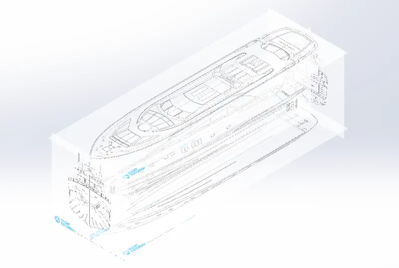
1. Setting of Blueprint
In this step all the image i.e. front view, side view, top view, bottom view and back view are set properly.
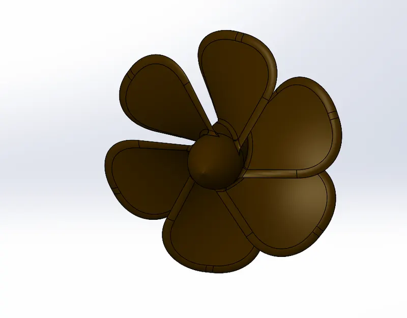
2. Propeller Modeling:
A propeller is a device with a rotating hub and radiating blades that are set at a pitch to form a helical spiral, that, when rotated,exerts linear thrust upon a working fluid, such as water or air.
While modelling propeller a revolve, extrude cut, Loft, circular pattern and fillet features are used.
3. Radar Modelling:
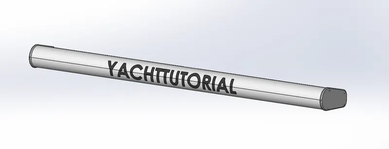
Radar (Radio Detection and Ranging) is a detection system that uses radio waves to determine the distance (range), angle, orvelocity of objects. It can be used to detect aircraft, ships, spacecraft, guided missiles, motor vehicles, weather formations, and terrain.
Extrude, extrude cut, Mirror, Split line and fillet commands where used while modelling the radar.
4. Hull Modelling:
A hull is the watertight body of a ship, boat, or flying boat. The hull may open at the top, or it may be fully or partially covered with adeck.
A top the deck may be a deckhouse and other superstructures, such as a funnel, derrick, or mast. The line where the hull meetsthe water surface is called the waterline.
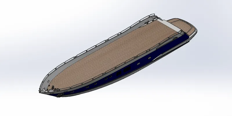
Outer body of Hull is modelled by using solidwork surface tool. Project curve feature is also used.
Few surface tools where also used like Lofted surface, Boundary surface, Extruded Surface, Trim Surface.
Other tools like swept boss and extrude cut are used.
While modelling of hull I learnt how to assign reference plane on different edge and point. Also, I learnt how to use sweep command.In modelling of hull part one there are different command used such as extrude cut ap to surface for making of window, the body ismodelled by using projected curve and surface tools.
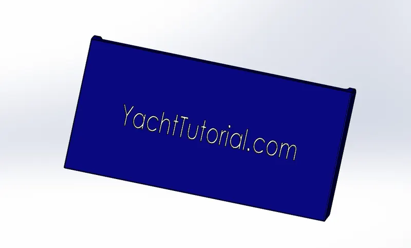
5.Garage door modelling:
Garage door are easy to model by using extrude boss and extrude cut.
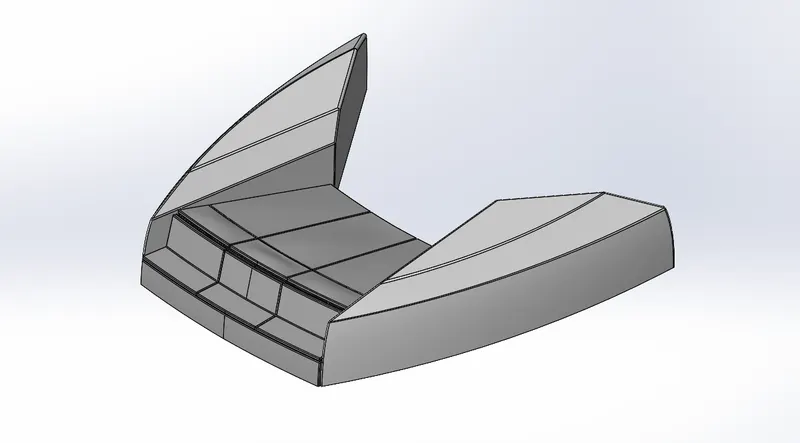
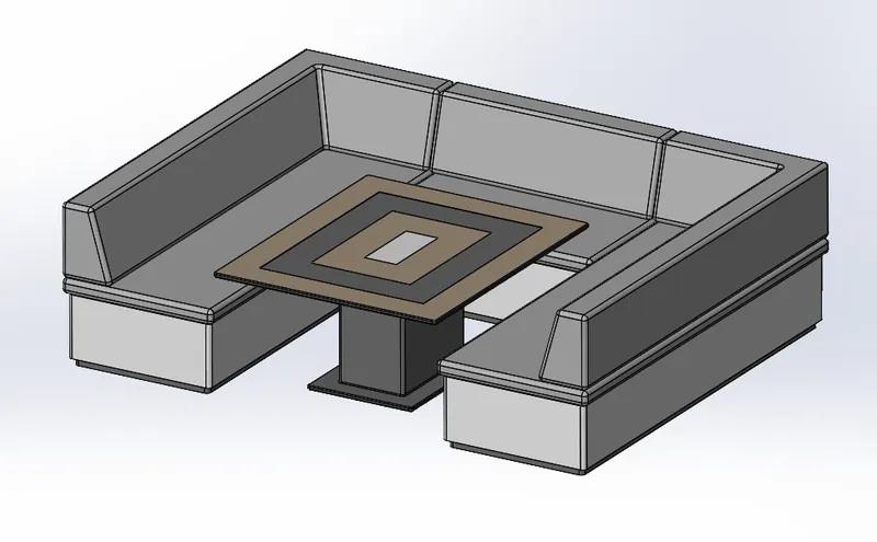
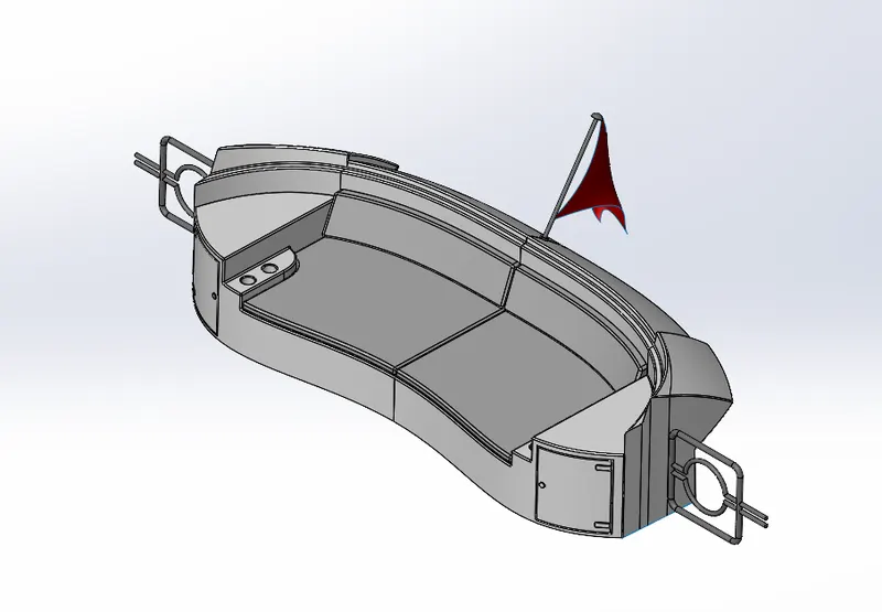
6. Front, Middle , Rear Seat Modeling:
Basically, three seat where model by using surface tool and khit surface feature.
Front seat
Middle seat
Rear Seat
7. Superstructure Modeling:
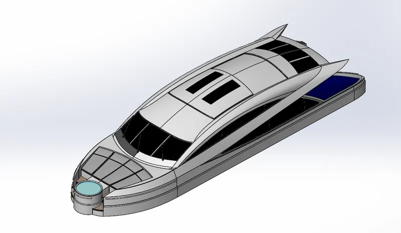
A superstructure is an extended construction of any building or platform that rises above the rest of the building or platform in adistinct manner. Thus, superstructure means to add a construction to an already existing structure. In ships this is the name given tothe part of the ship that emerges from the deck.
The feature which are used in modelling of super structure are surface feature, Knit surface, Swept boss, fillet, extrude boss and chamfers.
8.Modelling of Radar Mast:
Mast Marine radars are X band or S band radars on ships, used to detect other ships and land obstacles, to provide bearing and distance
for collision avoidance and navigation at sea. Radar is a vital navigation component for safety at sea and near the shore.
Extrude Boss, Revolved, swept, shell and mirror feature where used.
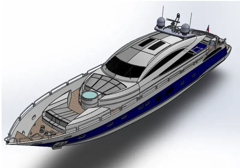
9. Assembly:
Isometric_View
Front View
Side View:
Camera view:
Top view:
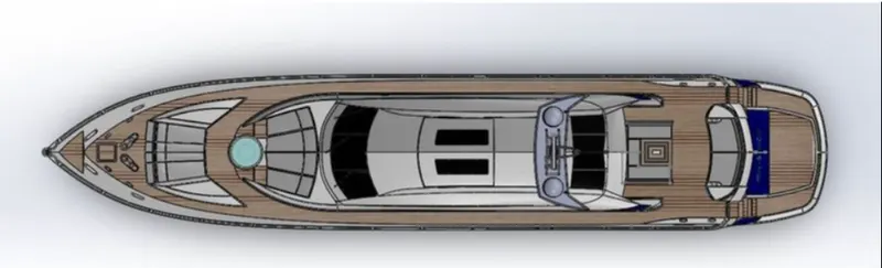
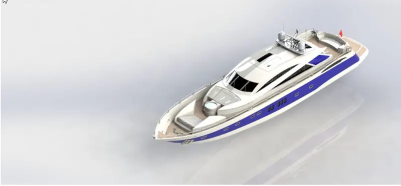
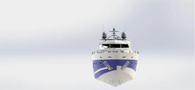
PHOTO REALISTIC RENDERING:
For creating photo realistic images of the Chopper we rendered the models. The process consists of adding cameras, lights,environment, scenes and backgrounds. All the while changing the properties of each feature, adjusting them to create the perfectappearance setting for our final model rendering.
Rendering of the model is done using below add-ins and software
Photoview 360
SolidWorks Visualize
Render Isometric view:
Render Front view:
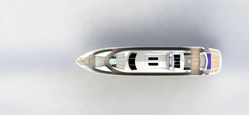
Render Top view:
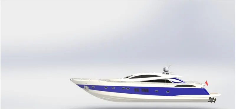
Render side view:
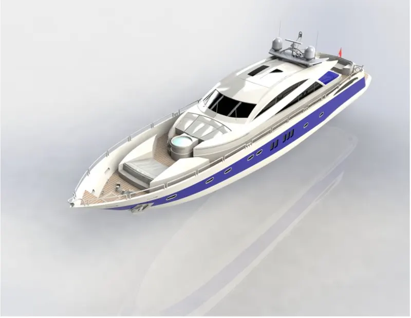
Render Camera view:
CONCLUSION:
Thus, by using Solidworks the parts modelling, and appearance were successfully designed
Using Solidowrks, the Sunseeker Predator Yatch assembly was done
By using Solidworks Visualize, the Photo Realistic Rendering of the Yatch was successfully made.