Wiring harness design in CATIA V5 - 3D modeling Week 5 & 6 Challenge
Route the following harness layout in Electrical workbench. Make assumption for harness bundle diameter 10MM. Use the connectors provided.
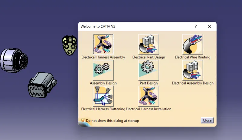
First of all start to this challange download all cad data and routing mapping data.
All connectors download from link and all file convert to electrically define and make them to into one procdut file and doing same which shown in videos of harness A and Harness B arrange them shown in image.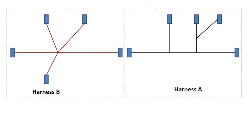
After arranging them to this manner started process which shon in tutorial like make harness A geometrical bundle and multibranchable add then start to routing bundle with connectors which electrically define.
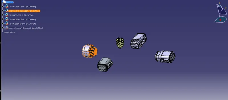
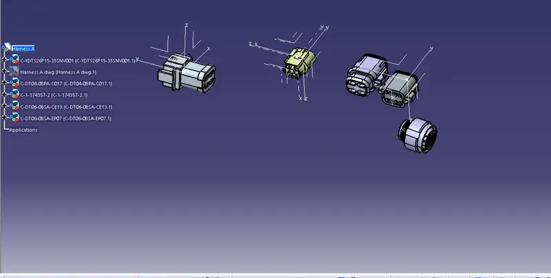
arranging all connectors like wise shown in images and start rounting with electrical harness assembly workbench.
Now doing this process make two harness A and B will vertically tile window.which shown in image.
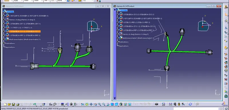
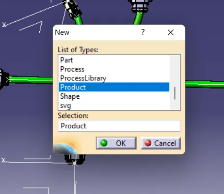
After this process make new products to join to harness together which shown in below image.
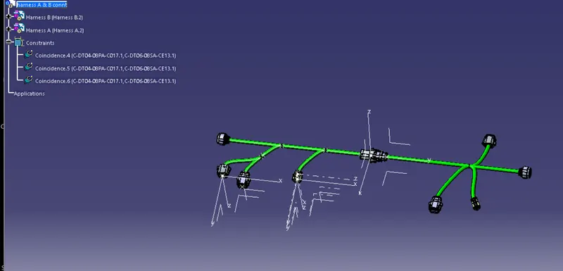
make to connetcors will be connect together electrically.
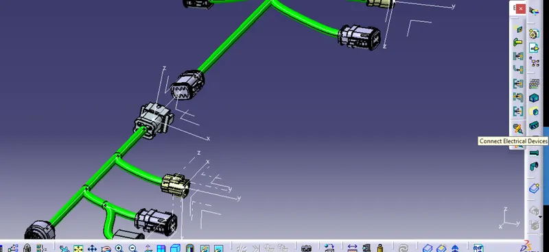
After doing that make all connectors will define of 3d annotation which shown in images.for 3D annotation make sure workbench switch electrical to assembly design .
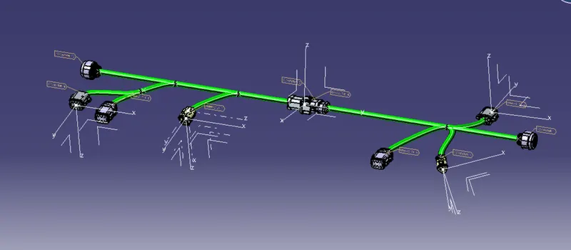
after doing all process we check bundle continutiy.its ok or not.

here in the above imagethe error represnt red light in Bend radius which show below and remove the error the rad light is show as green light which already shown in tutorial.
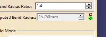
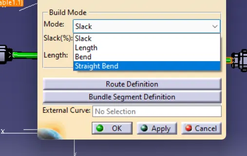
for Removing this error we have mant option like slack,bend radius otherwise we have differently to remove this error movement of connectors toward and make its error free and diffn option like tangentcy will also major role in routing the bundle in softwere.
Above image the red line display the error in Continuity.To show this bundle warning .
to check bundle Continuity see images which shown below.
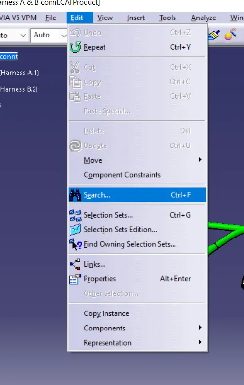
go to edit and search option and go to advance of that setting.
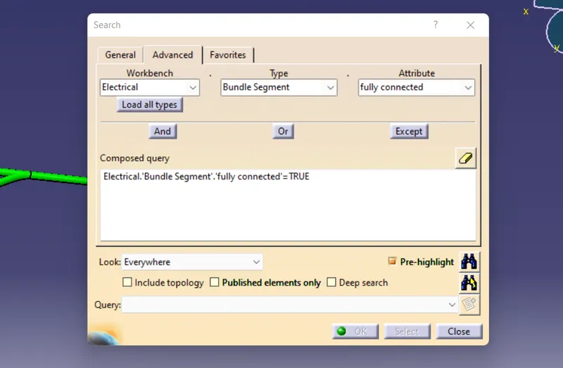
In advance see Workbench (electrical)>Type(Bundle segments)>Attribute(Fully connected) and make true to see which brach is not connected
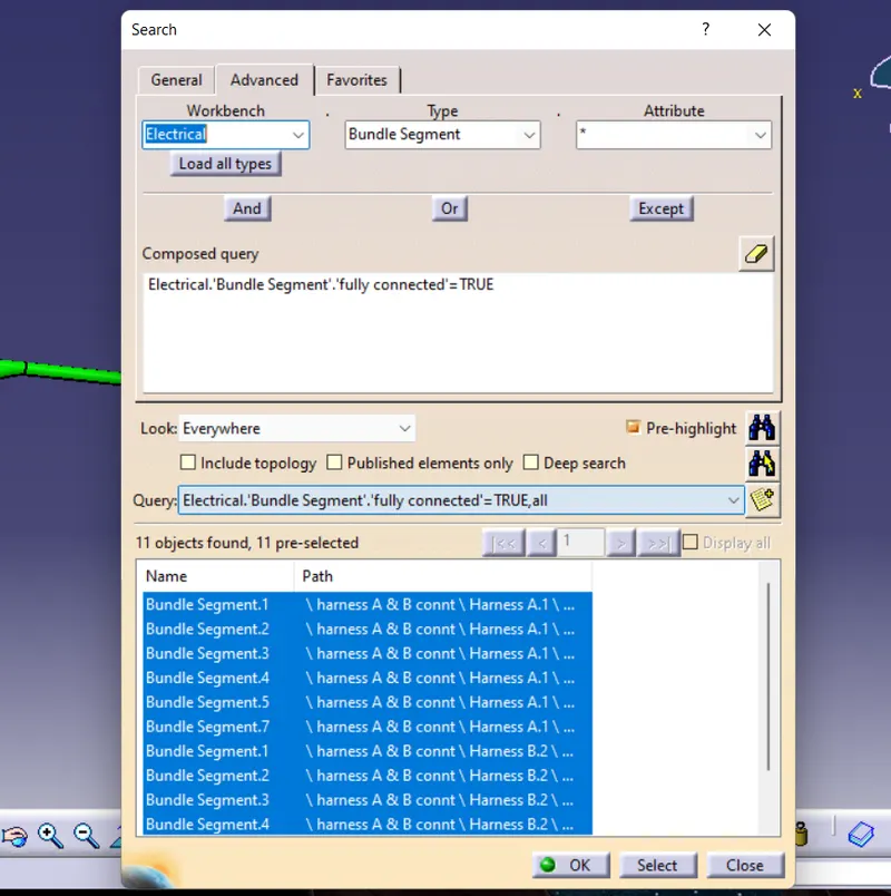
Here there is no error in bundle Continuity and its ok.
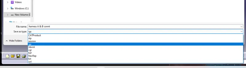
after doing all process convert to this file into CAT.part file then its convert to .igs format to open in different softwere like CREO,SOLIDWORK etc.
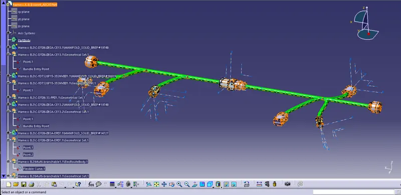
After this doing this save as igs format.
Here all Files of related to challange is attached.