Wiring harness design in CATIA V5 - 3D modeling Week 5 & 6 Challenge
AIM:
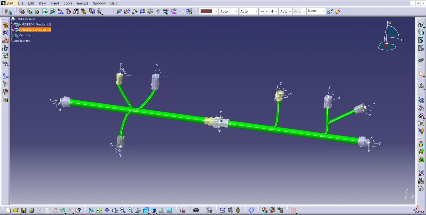
Route two electrical harnesses as per the given layout and interconnect them as a single harness assembly and then check for bundle continuity, bundle warnings, and then give annotations to the final harness assembly.
STEP 01:
Download the all CAD data of connectors and define all the electrical connectors geometrically and electrically so that they can be used in the wiring harness.
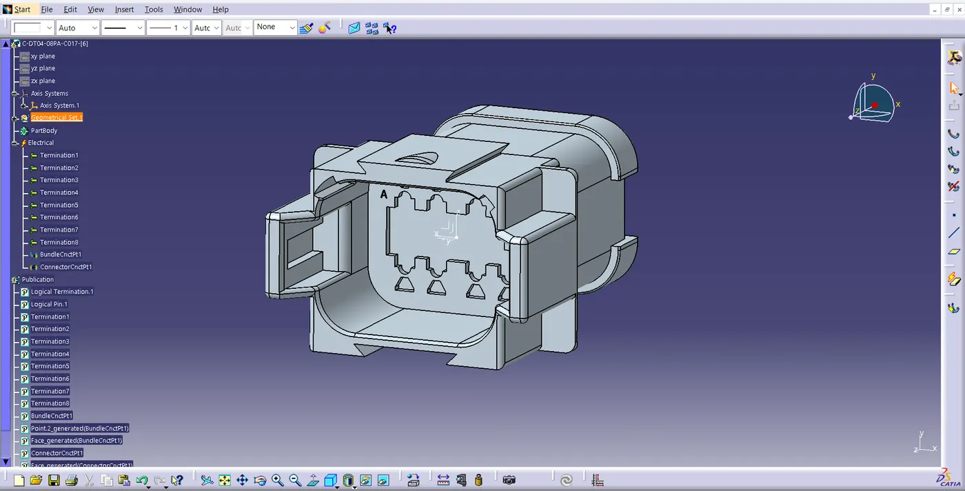
In the Above figure We Have Taken from given source & Merged into Catia V5.
1. Go To the Part design workbench & Taking A middle Point From The Connector Connecting Side As Well As Bundle Connecting Side.
2. Taking the axis Origin of Connector connecting Point.
3. Adusting the y-axis is normal to the face of connector connecting Point & X-axis would be locking side & Z-axis would be Up or down side.
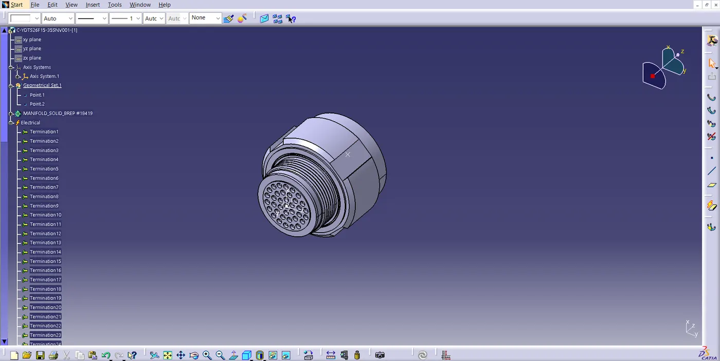
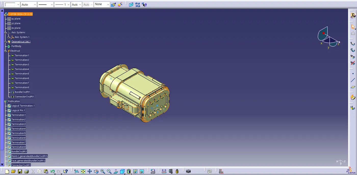
4. Then go to the electrical part design workbench after that defined it as a connector & Add no of terminals it has & defining the connector connection point As well as bundle connection point with respect to their faces & Respresentations.
- Follow these Procedure for all 10 Connectors.
ex:
STEP 02:
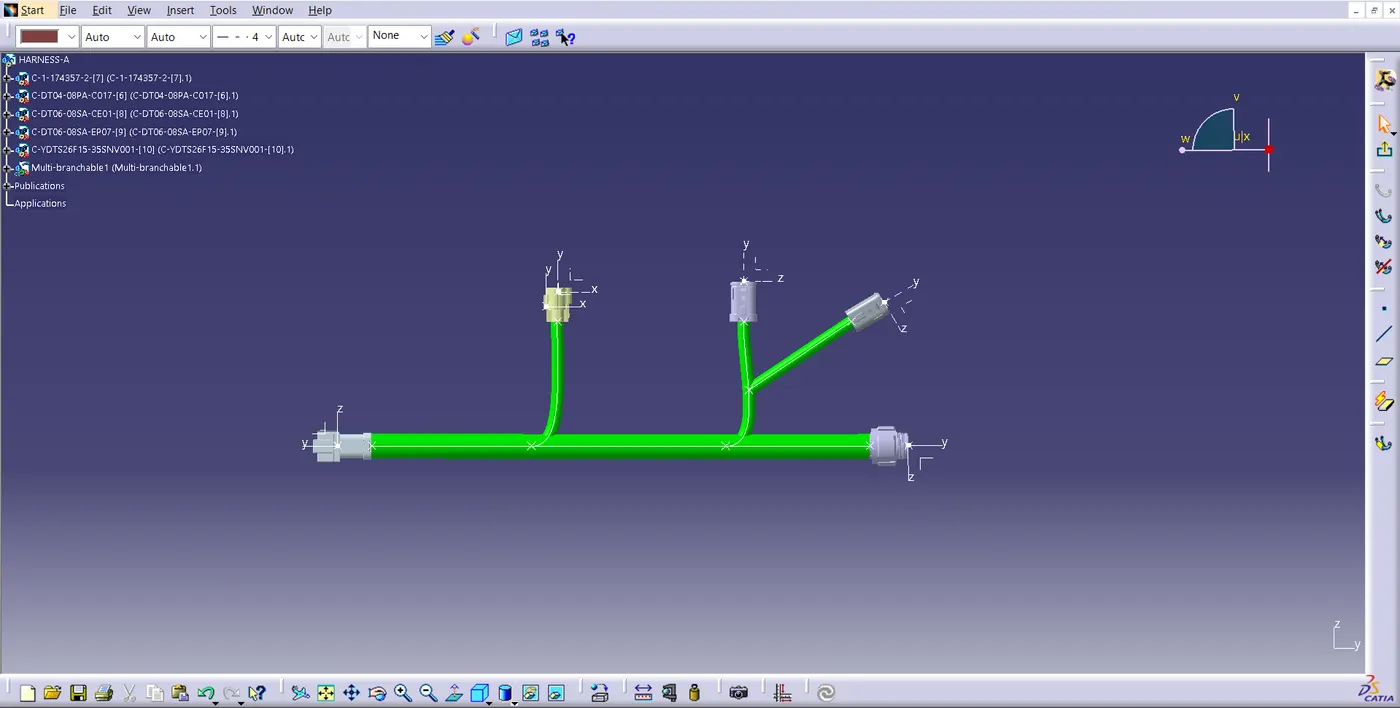
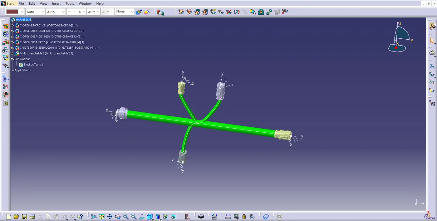
Create harness A and harness B as shown below by using the electrical harness workbench in CATIA V5.
First, all the connectors are placed at their desired locations. Second, bundle segments are created between the connectors with branch points and branches as shown below.
Bundle diameter is assumed to be 20mm and 10mm for different bundle segments. Bend ratio is given as 1.4 and slack is given as 0% for all the bundle segments.
- HARNESS A
- HARNESS B
STEP 03:
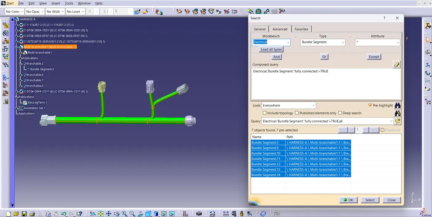
After Harness A and Harness B are created the next step is to check the bundle continuity.
- By Clicking the Ctrl+F Key we go the pop up .
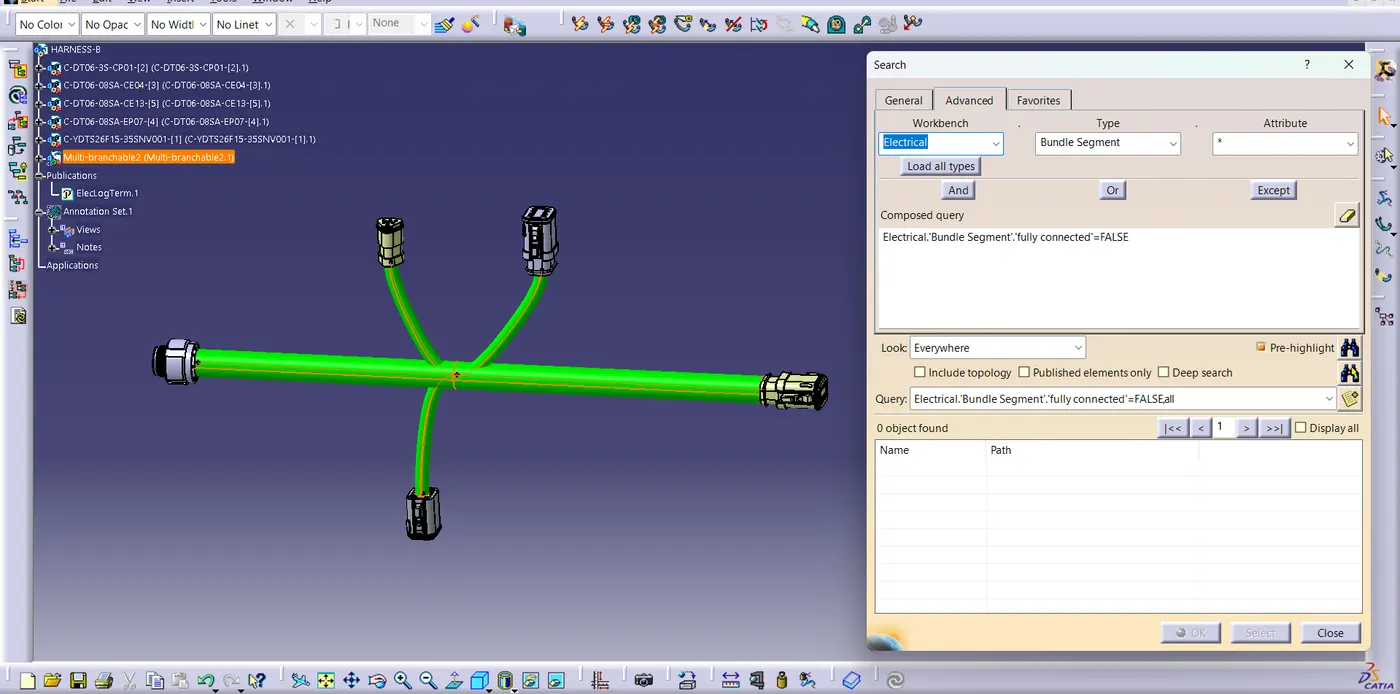
- Then Go To The Advanced & Select the Electrical workbench & select the bundle segment on type & go to the attributes select the Fully Connected.
- Selecting the "TRUE" option will show all the connected bundle segments while selecting the "FALSE" option will show all the non-connected bundle-segments.
- HARNESS A in TRUE option:
- HARNESS B in FALSE option:
STEP 04:
we have to interconnect the Wiring Harness A and Harness B electrically.
STEP 05:
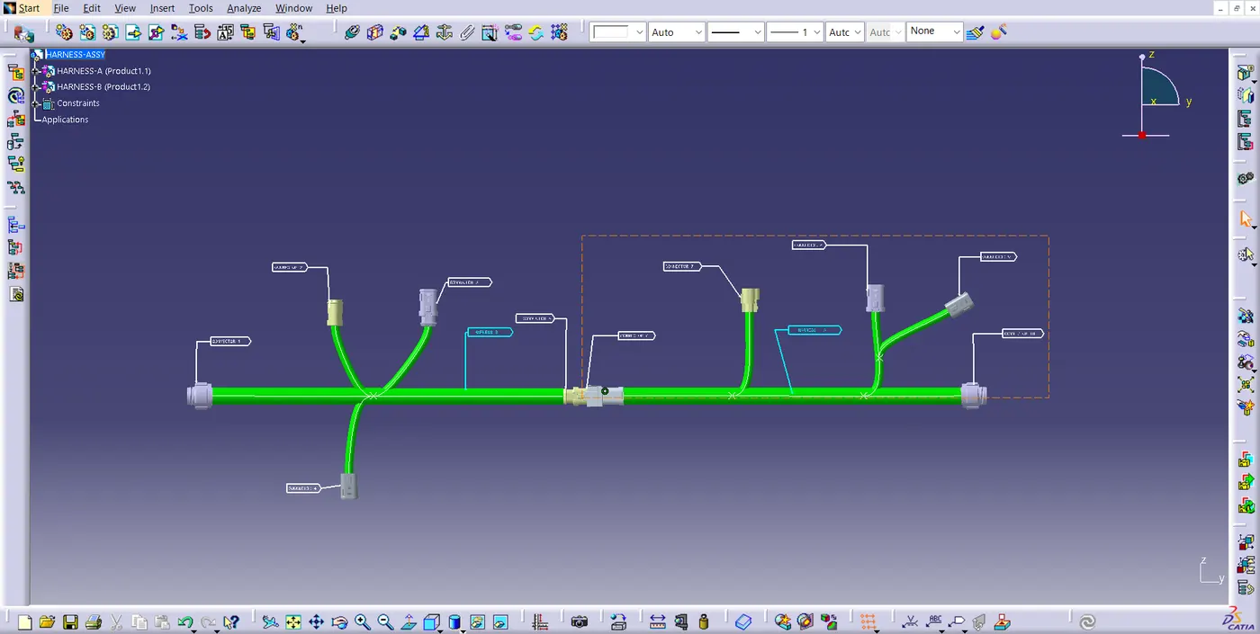
Adding annotation for all the electrical connectors.
Annotations are used to show connector functions and additional information. They are defined in Assembly Design Workbench of CATIA V5.
STEP 07:
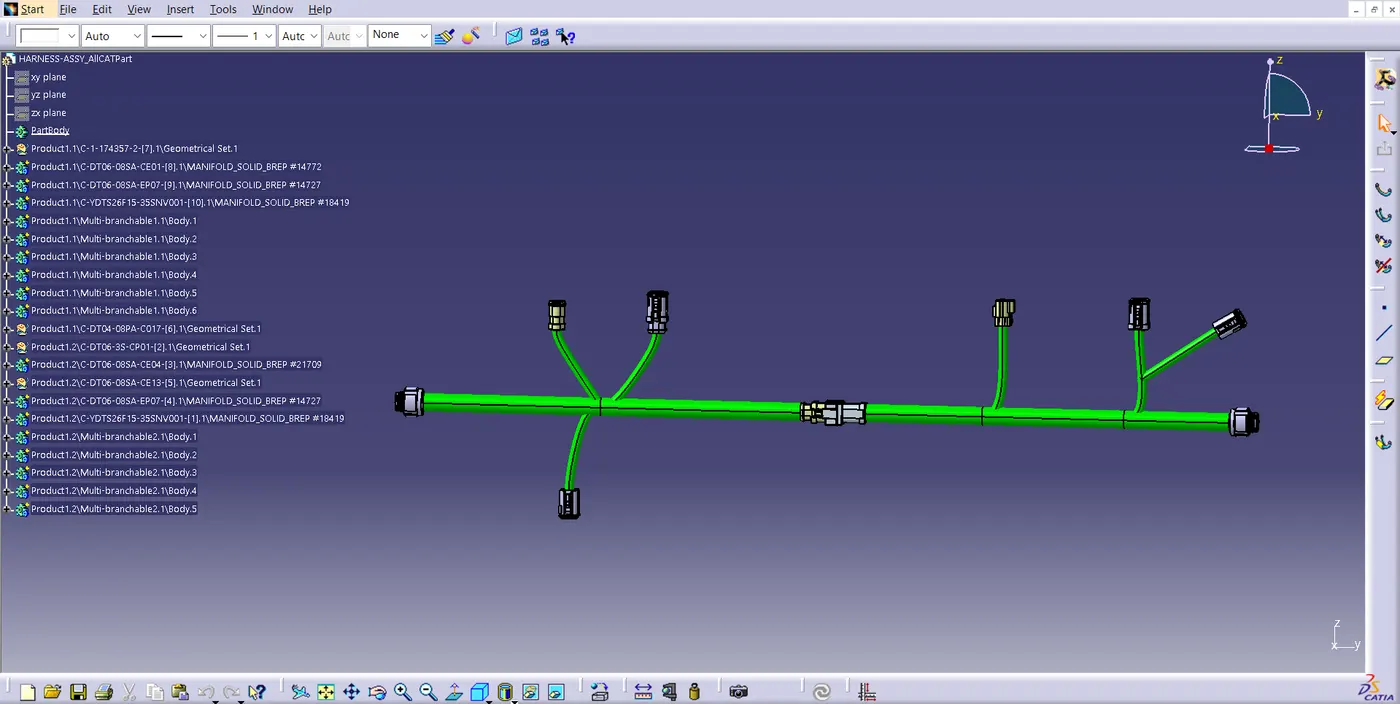
We have to convert out Final Harness Assembly file into IGS format. In order to do this we should follow the steps as shown below.
- Mechanical Assembly Workbench.
- Select Tools.
- Select Generate CAT Part from Product option
Once the CAT part is created the whole product file is converted into a single part.
In the end, we can use the "SAVE AS" feature to save the CAT part file as IGS file.
....