Wiring harness design in CATIA V5 - 3D modeling Week 5 & 6 Challenge
Wiring harness design in CATIA V5 - 3D modeling Week 5 & 6 Challenge.
Input Data:
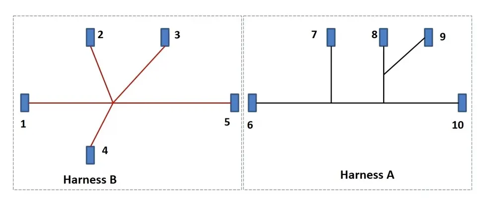
Route the following harness layout in the Electrical workbench. Make assumptions for harness bundle diameters. Use DT connectors. After completion of routing do the followings,
- Check the bundle Continuity. Add snap of result in submission
- Add annotation to all connectors. Make an assumptions for annotations like connect 1 , 2 etc
- Check for the bundle warning. Add snap.
- Generate CAT.part of harness assembly and convert is in. igs format.
Steps involved in Harness Assembly:
● Download connector 3D data from www.te.com
● Converting the Mechanical part into the Electrical part for that I had followed the following steps.
Connector Definition:
Connector 1: C-DT06-08SA
- Import the downloaded step or igs file into the CATIA mechanical
- part workbench and save as cad part.
- Define the Bundle Entry Point.
- Define the Connector Connection Point.
- Define Connector Connection Axis. Y-Axis should face the other mating part/direction and X-Axis should face the lock,
- Now switch to the Electrical Part Design Workbench and define the connector using Define Connector Command with Name and No. of Terminals.
- Define the Bundle Connection Point. Face as Representation, Bundle Entry Point as Point, and Same face as Representation for Initial Condition.
- Define the Connector Connection Point. Connector Connection Point as Representation, Mating Face as Contact, Y-axis as Coincidence, and X-Axis as Orientation.
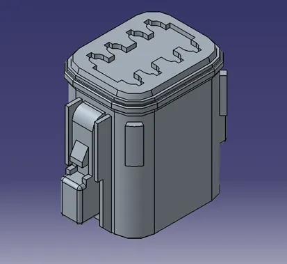
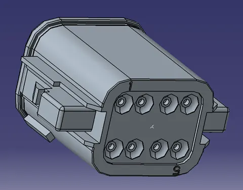
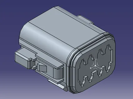
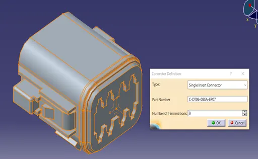
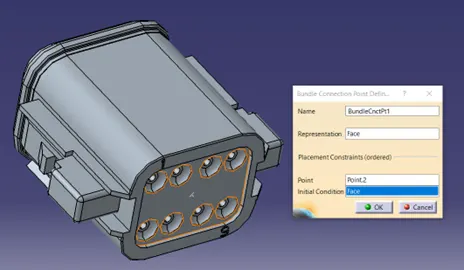
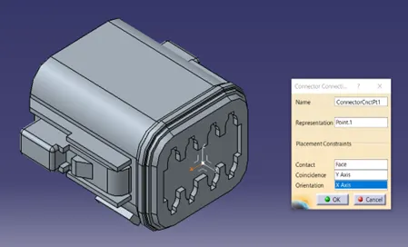
So likewise, all the connectors are electrically defined.
Now Create the Electric wire harness context assembly and Geometric bundle as a subassembly containing all the electric parameters as shown below,
The Harness Context Assembly - this is the top-level product file that contains the harness Geometrical Bundle/Assembly and the wire harness electrical bundle. Here Harness A and Harness B are created as separate geometric bundle in the main context assembly.
Harness A:
After all the connectors are defined, the workbench was switched to Electrical Harness Assembly where Geometrical Bundle was activated. All the connectors were routed using the Multi-Branchable Document command.
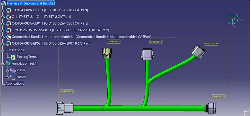
Connectivity Check:
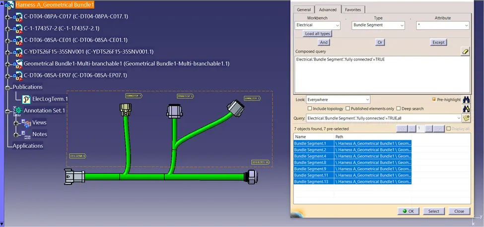
Bundle continuity of harness A is checked whether the bundle connection is continuously connected or not. The image below shows the true value of branches which means all the bundles are fully connected.
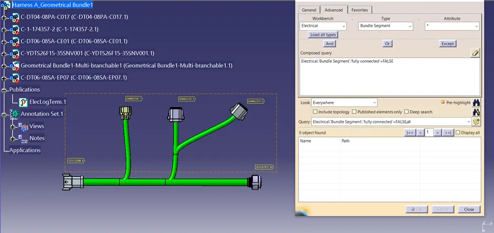
The same analysis is done by false attribute, which shows the bundle which are not connected to each other. The image below is not displaying any object after a search which shows all the branches are fully connected to each other.
 To check the bundle warning:
Bundle warning sign shows yellow exclamation mark (!) on the multi-branchable product. And on the bundle segment. Bundle warning is also highlighted as a red mark in front of the bend radius in-branch definition, which justifies the inappropriate bend radius of the branch. Below images of harness assembly, A, shows no bundle warning
● No yellow exclamation mark in product and bundle segment
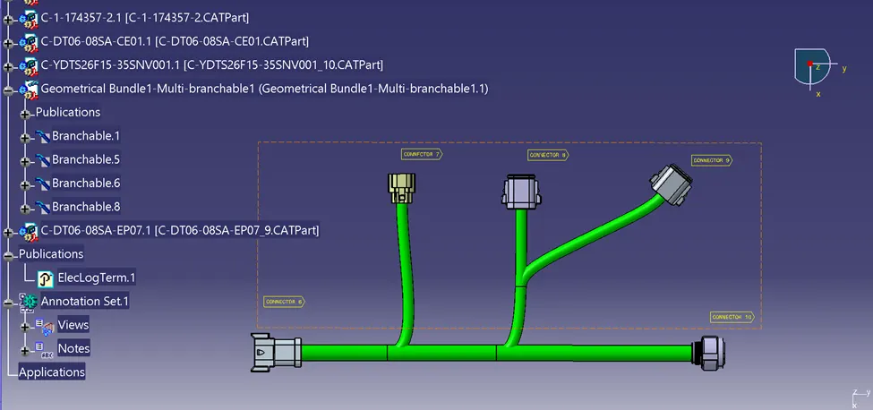
Harness A generated as a CATPART FROM PRODUCT and saved as an igs file.
Harness B:
After all the connectors are defined, the workbench was switched to Electrical Harness Assembly where Geometrical Bundle was activated. All the connectors were routed using the Multi-Branchable Document command.
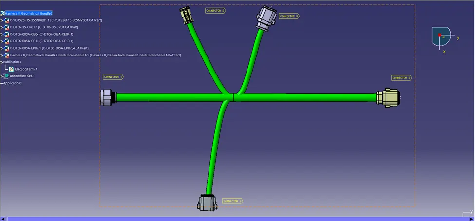
Connectivity Check:
Bundle continuity of harness B is checked whether the bundle connection is continuously connected or not. The image below shows the true value of branches which means all the bundles are fully connected.
The same analysis is done by false attribute, which shows the bundle which are not connected to each other. The image below is not displaying any object after a search which shows all the branches are fully connected to each other.
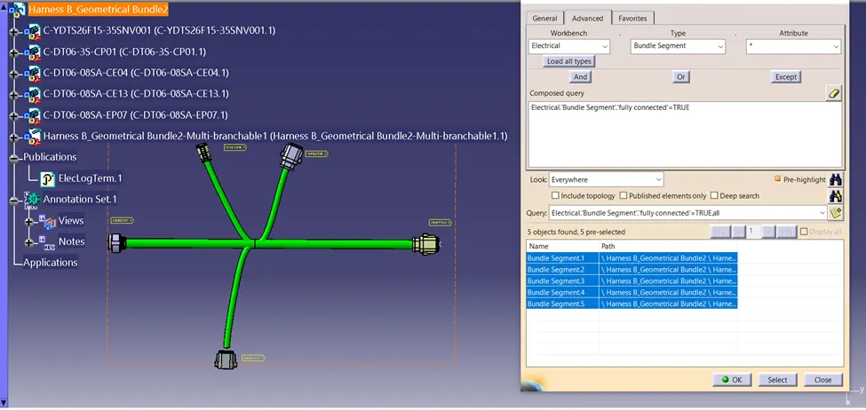
To check the bundle warning:
Bundle warning sign shows yellow exclamation mark (!) on the multi-branchable product. And on the bundle segment. Bundle warning is also highlighted as a red mark in front of the bend radius in-branch definition, which justifies the inappropriate bend radius of the branch. Below images of harness B, shows no bundle warning
● No yellow exclamation mark in product and bundle segment
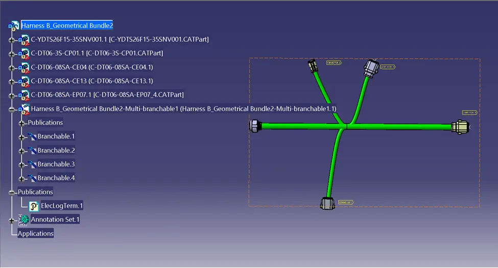
Harness B generated as a CATPART FROM PRODUCT and saved as an igs file.
Harness assembly of Harness A & Harness B:
Harness A & Harness B are electrically connected with each other by male connector 5 and female connector 6.
Select connector 5 in harness A and connector 6 in harness B both harnesses are connected electrically.
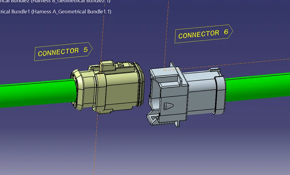
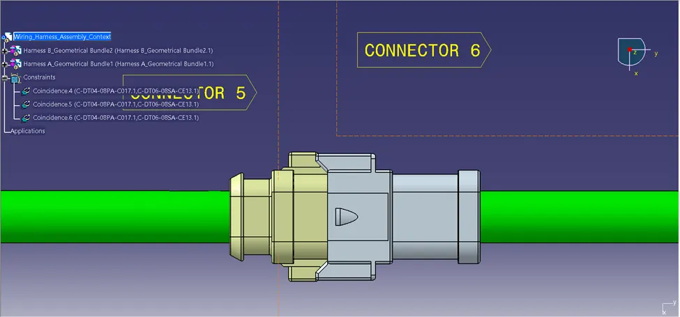
Fully electrically connected harness A&B are shown below
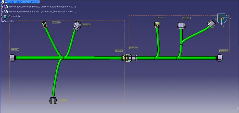
Product saved as CATpart & igs file also saved to open in any other software.
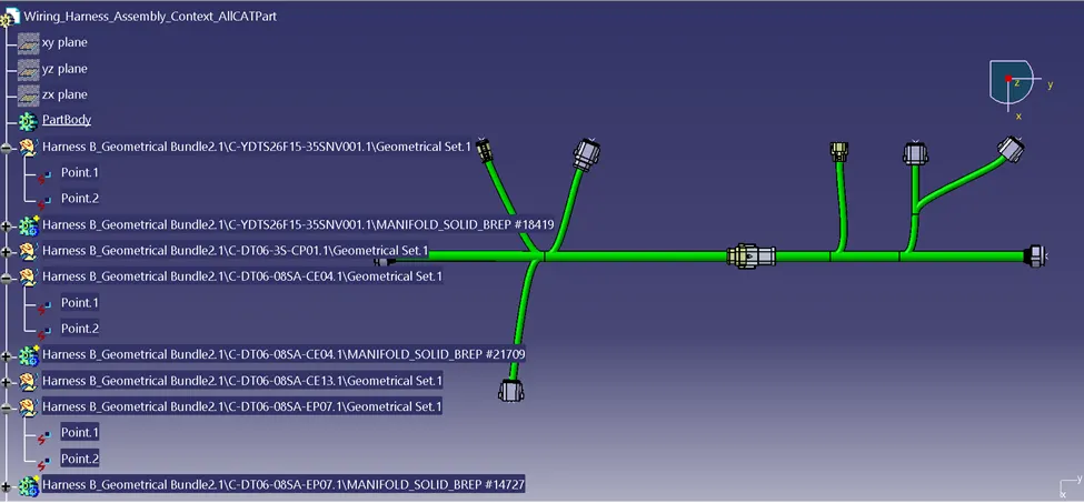
Note: I am not able to submit my challenge so I attached as gdrive link
https://drive.google.com/file/d/1qN-3wfvYOGD5axo5-9-yPlGi8Zeew7t-/view?usp=drive_link