Wiring harness design in CATIA V5 - 3D modeling Week 5 & 6 Challenge
AIM:
Route the given harness layout in electrical workbench with the given connectors. And after completion of routing do the given tasks and provide the images of the tasks.
OBJECTIVES:
- Check the bundle continuity
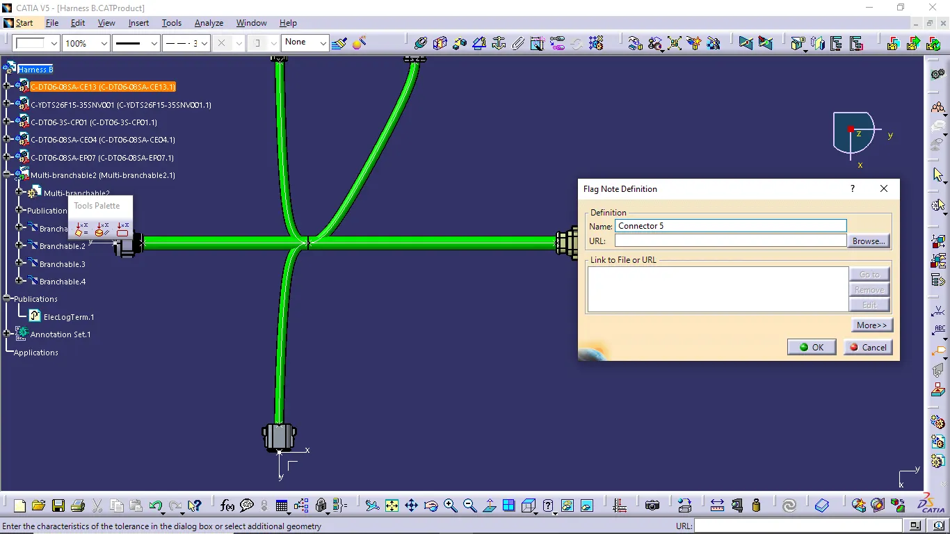
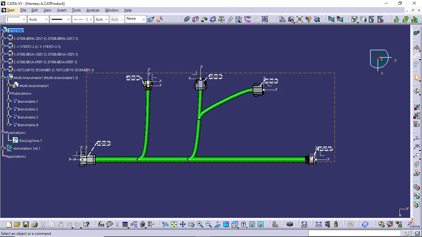
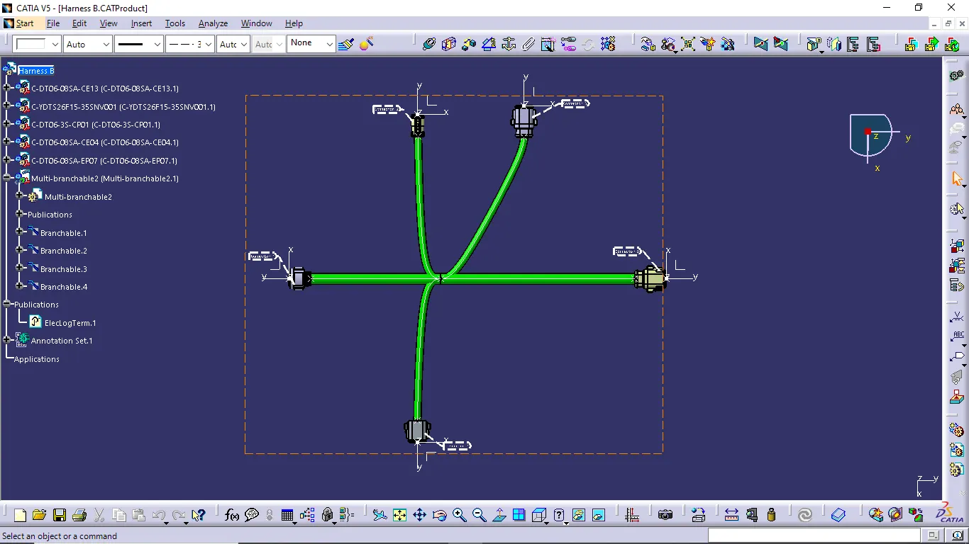
- Add annotation to all connectors
- Check for the bundle warning
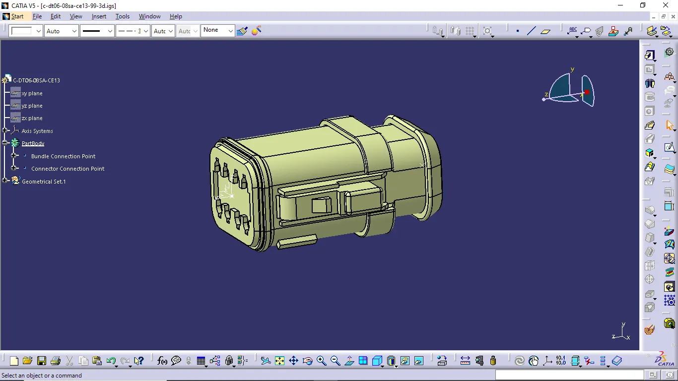
- Generate CAT.part of harness assembly and convert is in .igs format.
ROUTING PROCESS:
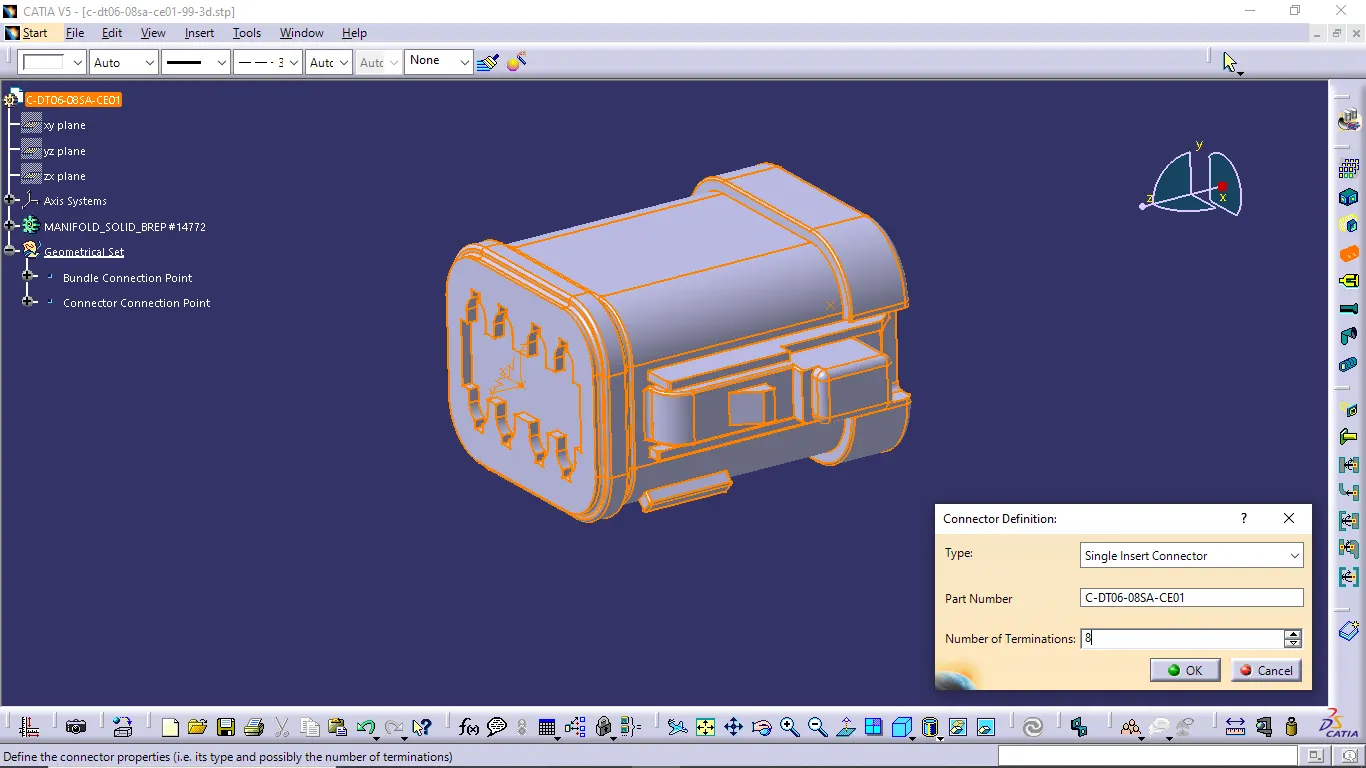
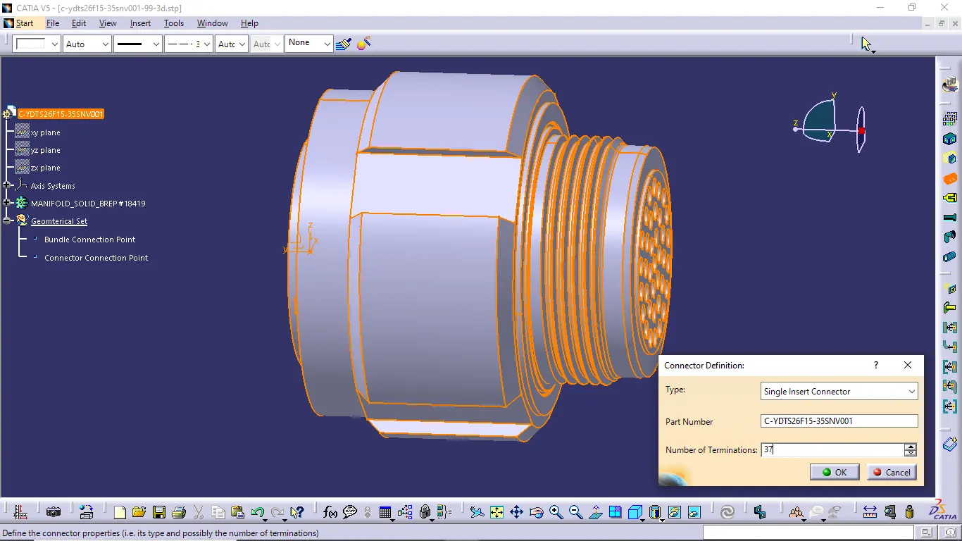
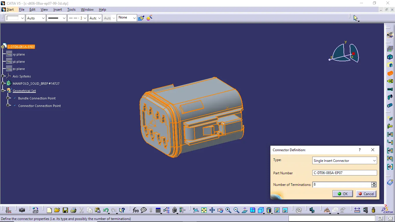
- In first we want to define all the connectors as an electrical component then we do next process
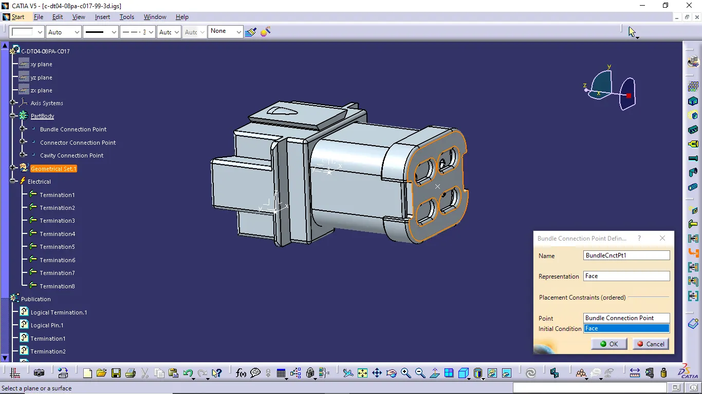
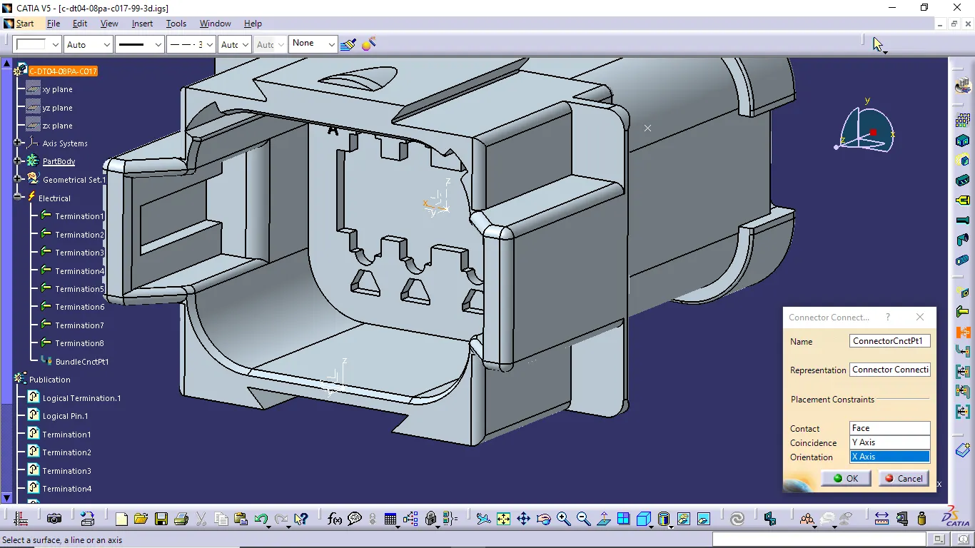
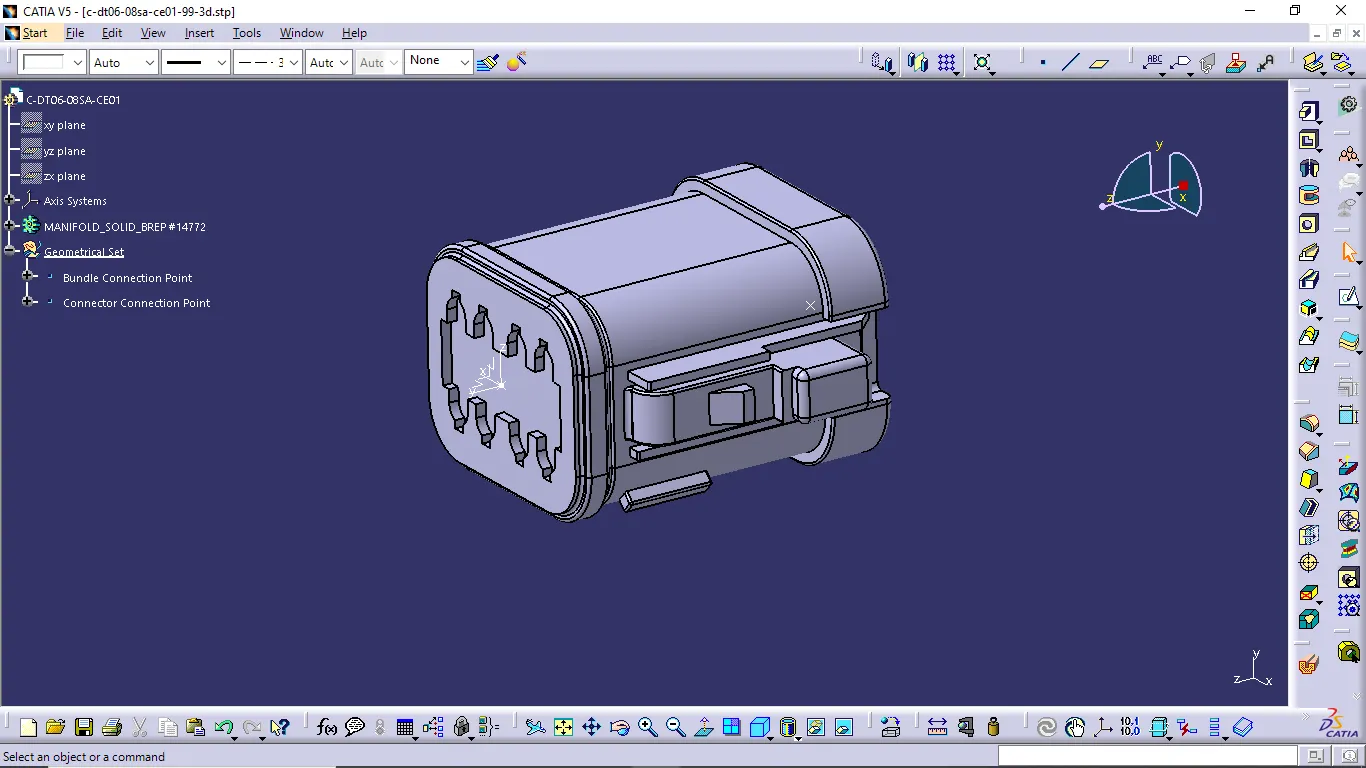
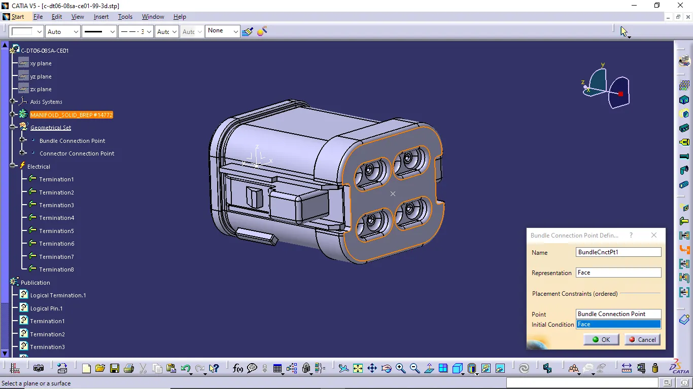
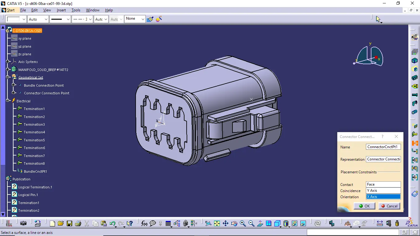
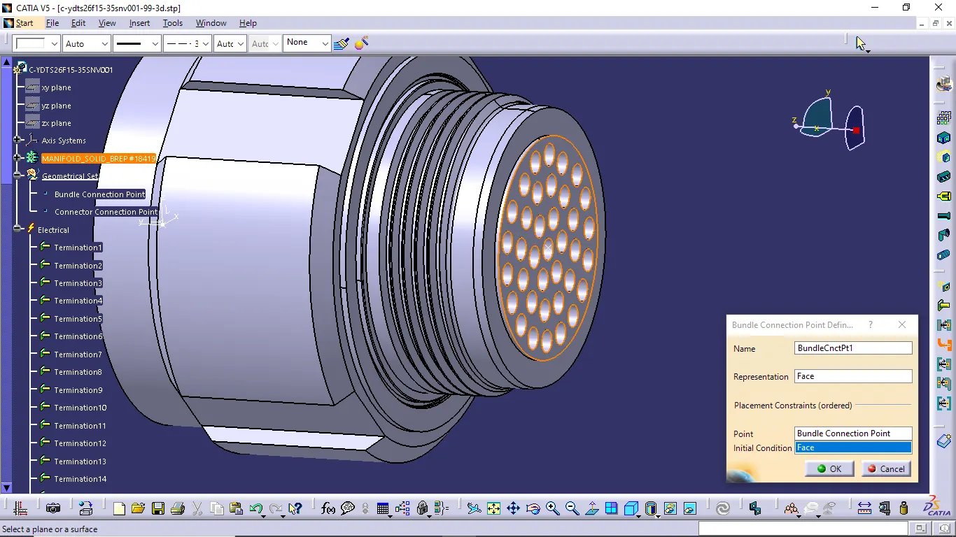
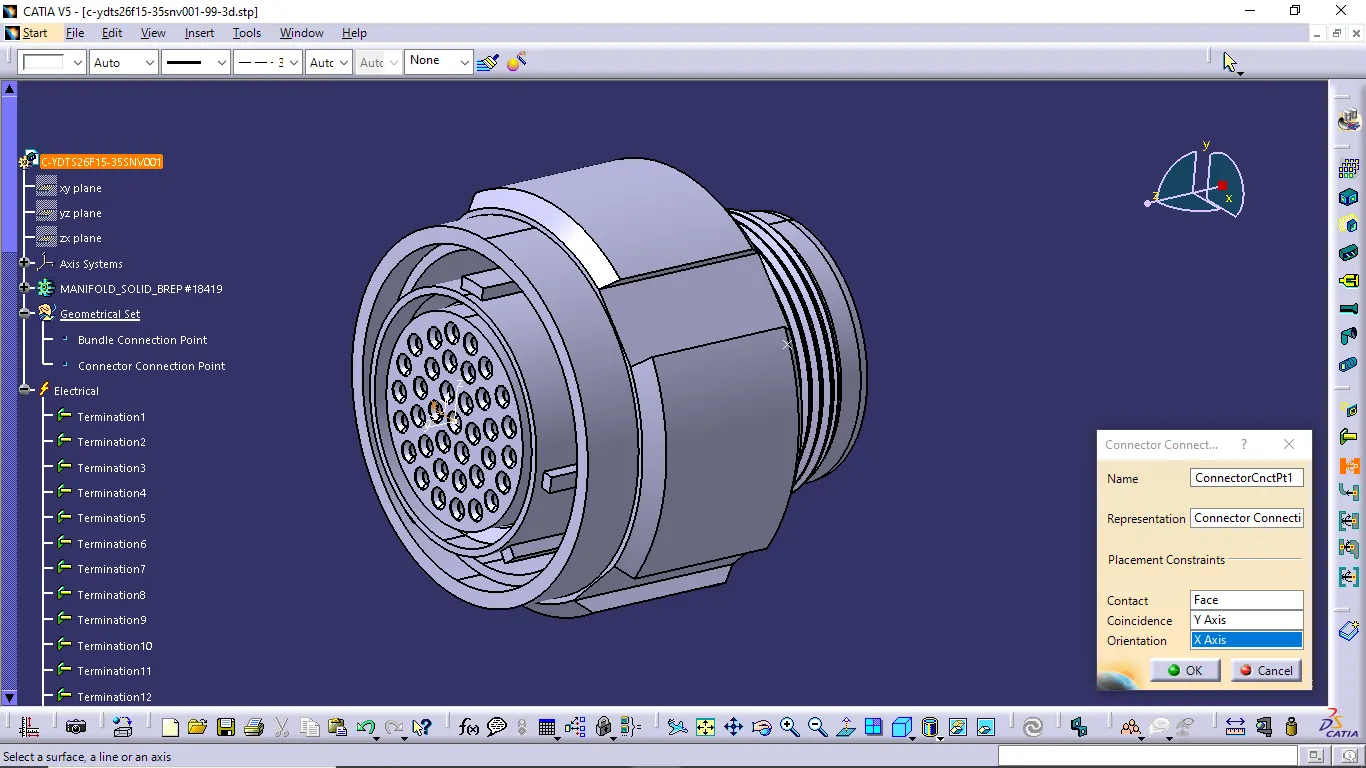
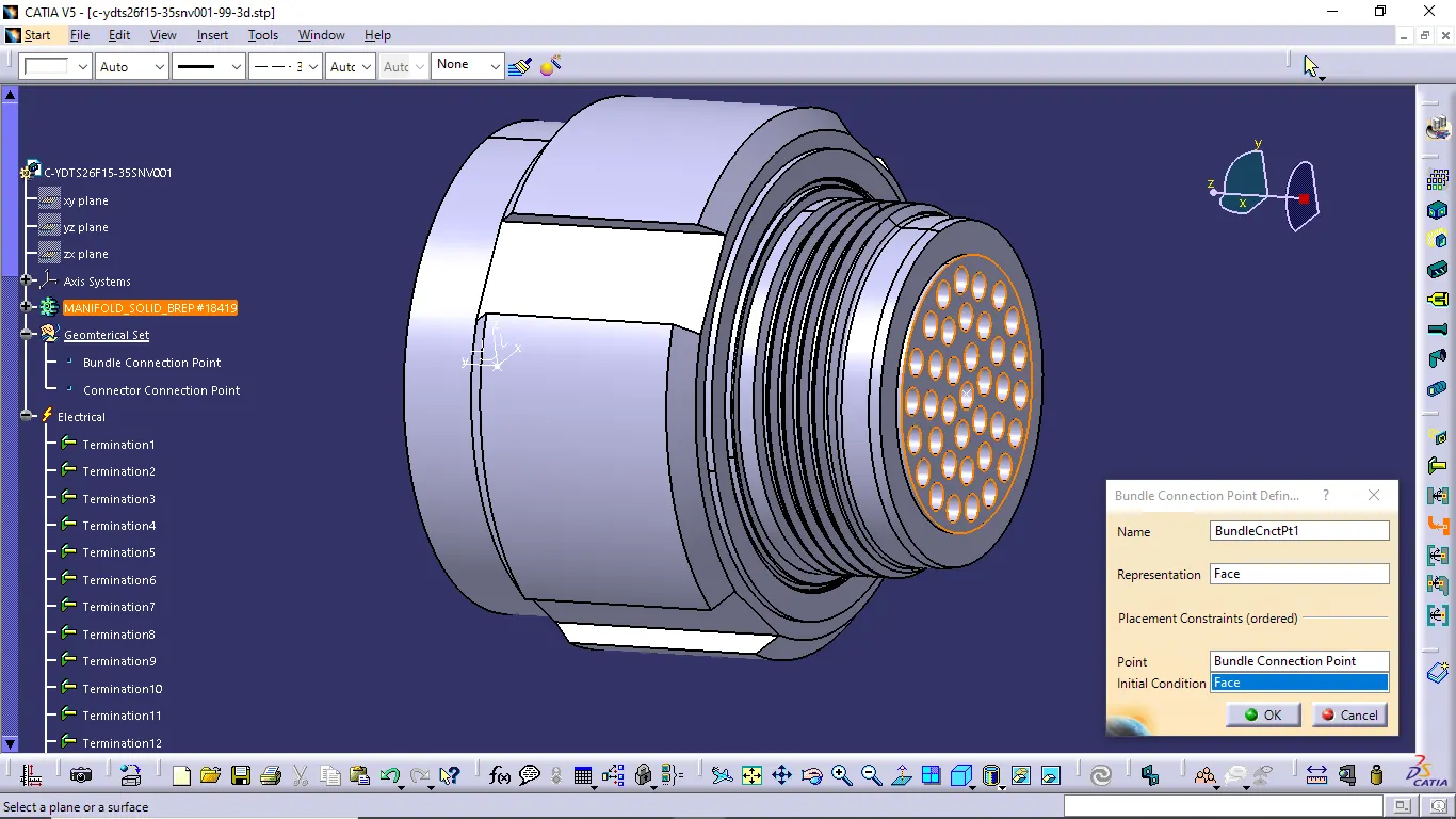
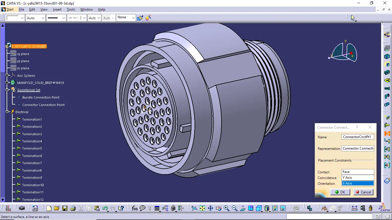
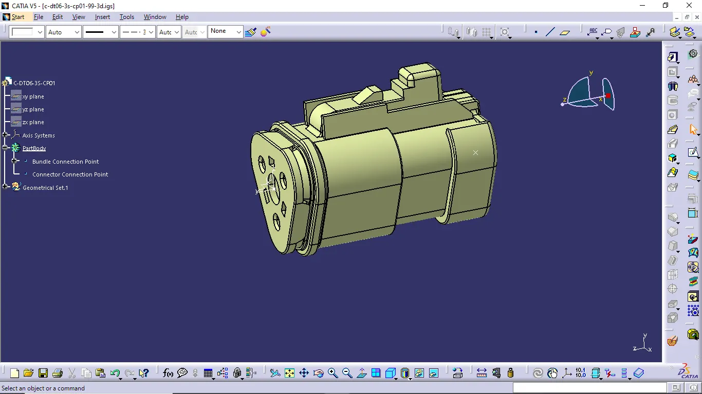
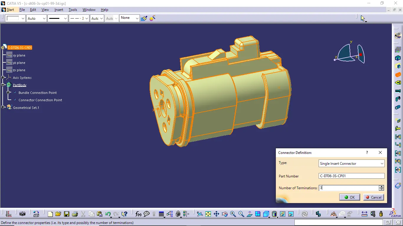
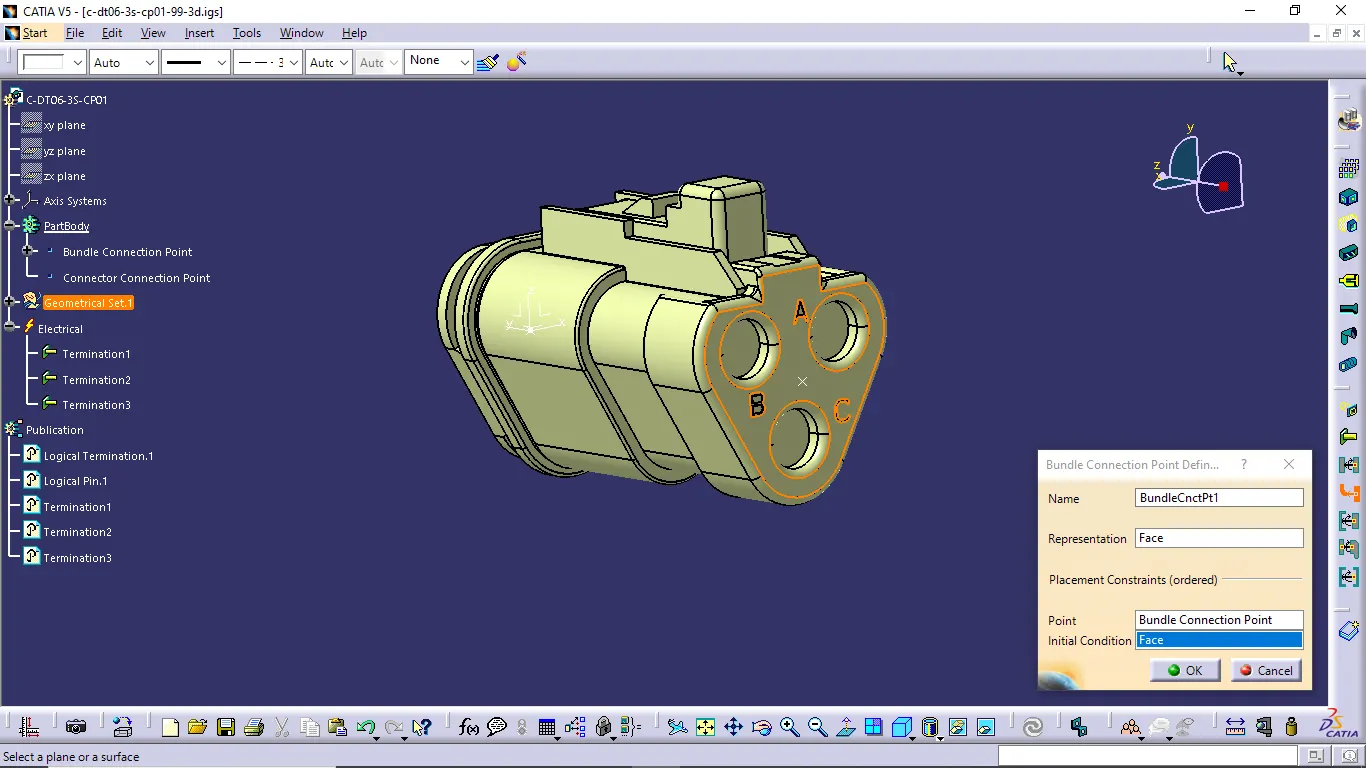
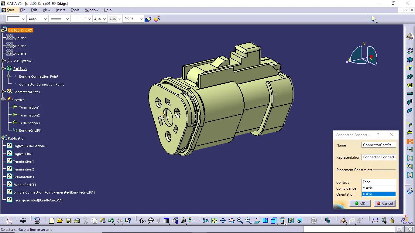
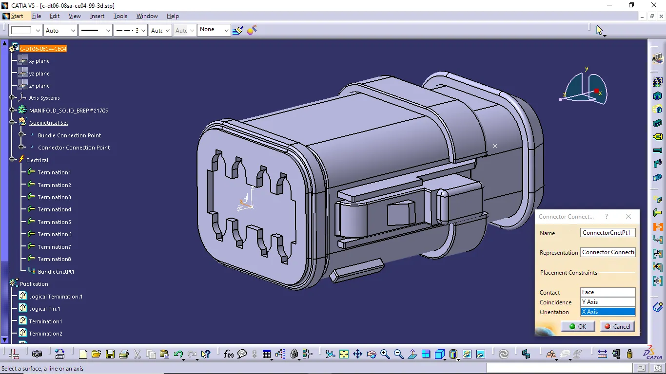
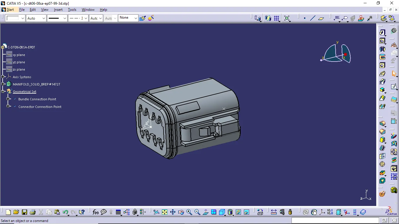
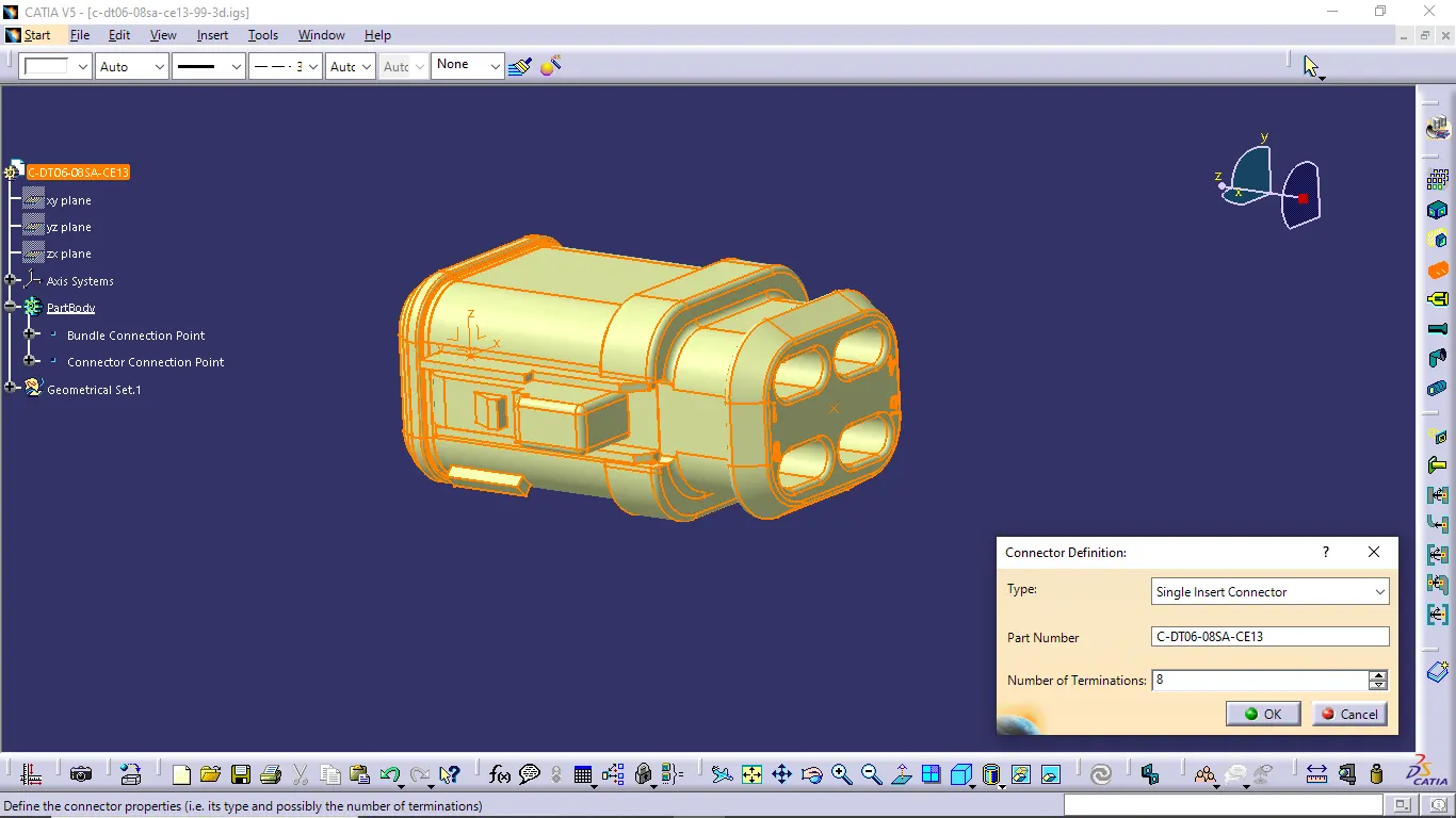
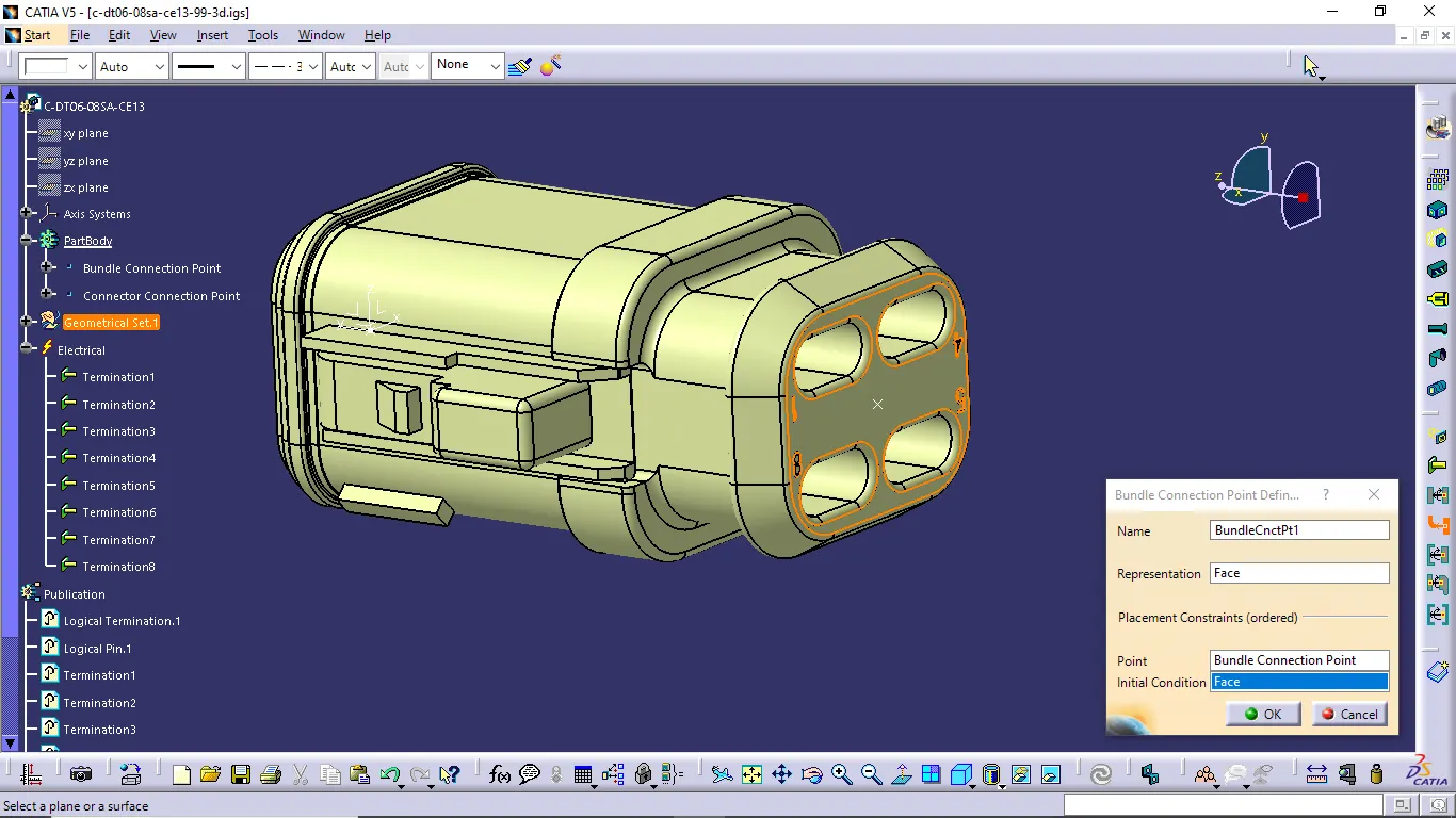
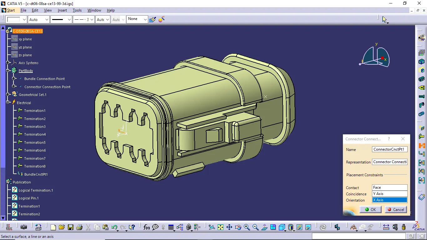
- We want to create the bundle connection point, connector connection point and define all connectors electrically.
Connector 7:
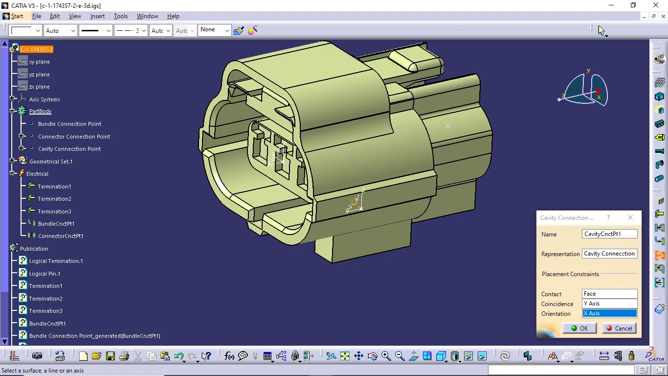
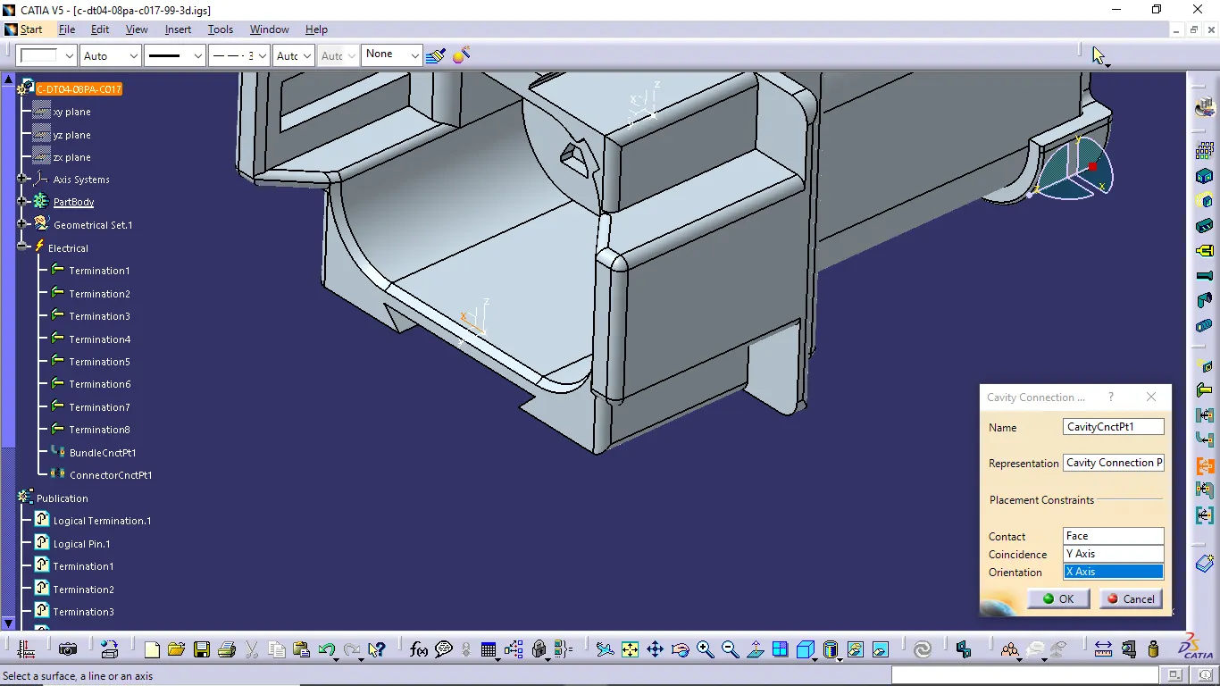
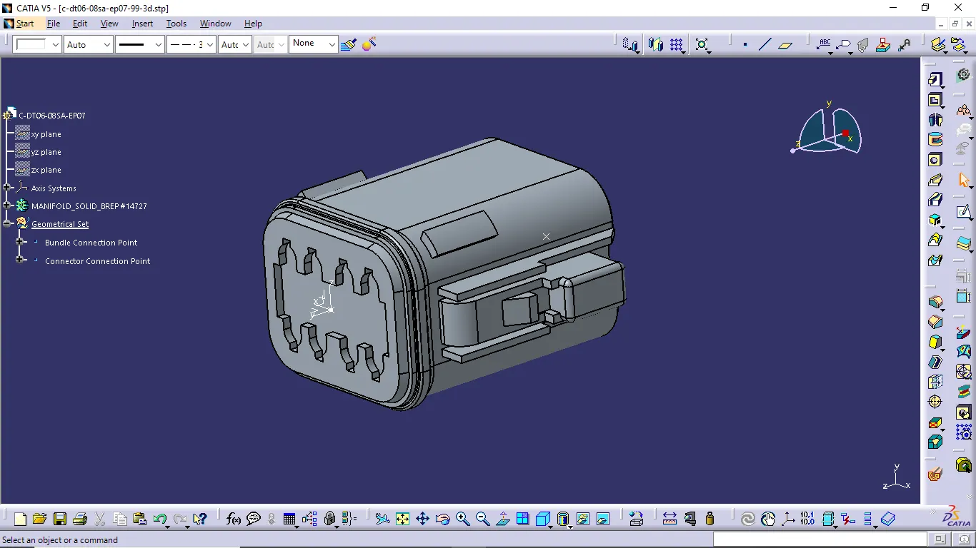
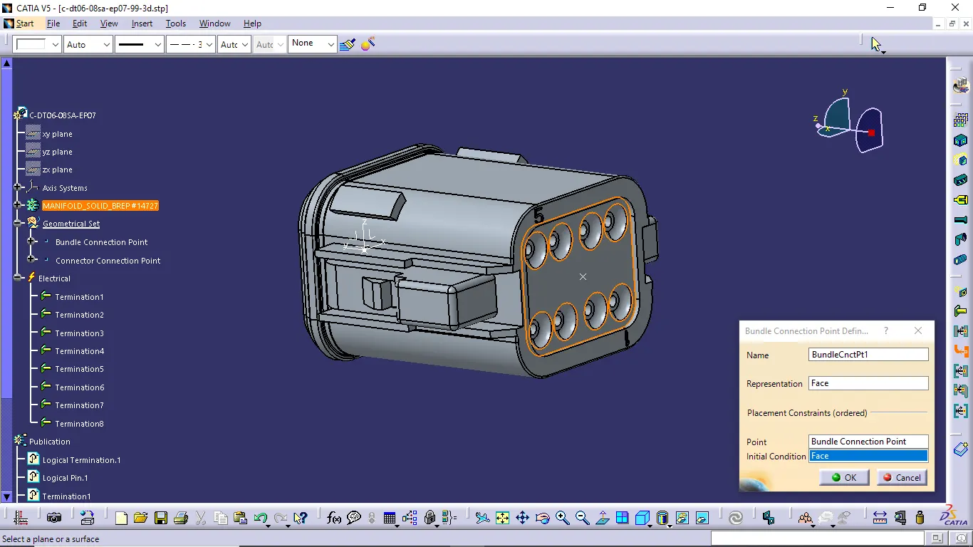
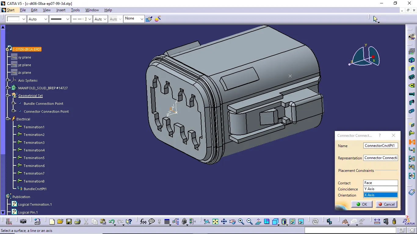
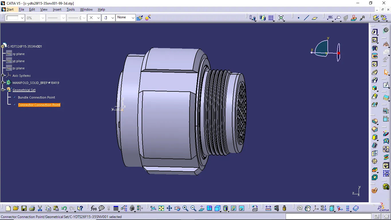
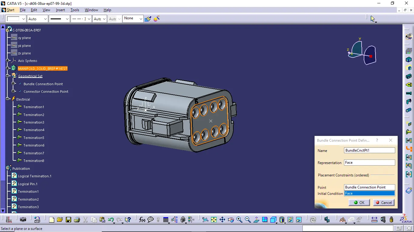
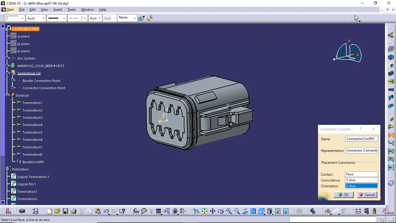
- Creating bundle connection point, connector connection point and Cavity connection point
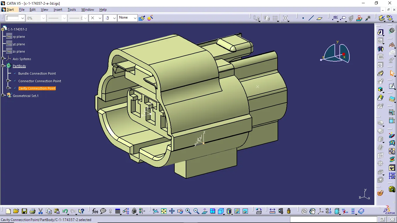
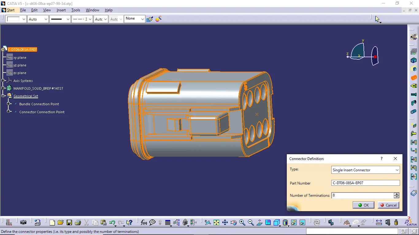
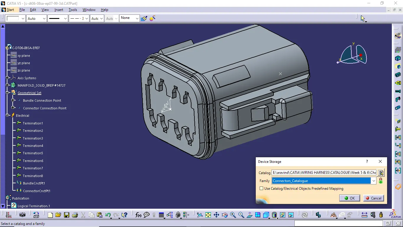
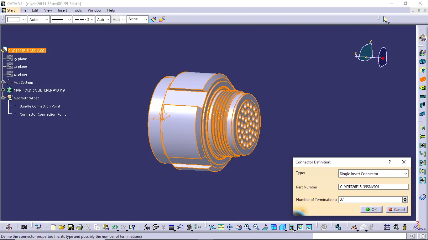
- Define connector as an electrical part and define bundle connection point, connector connection point and cavity connection point
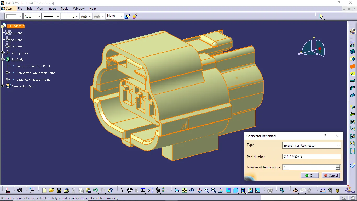
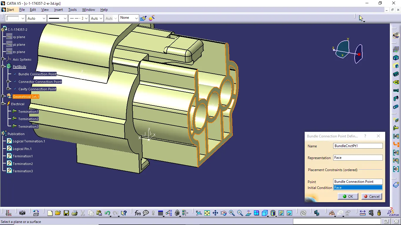
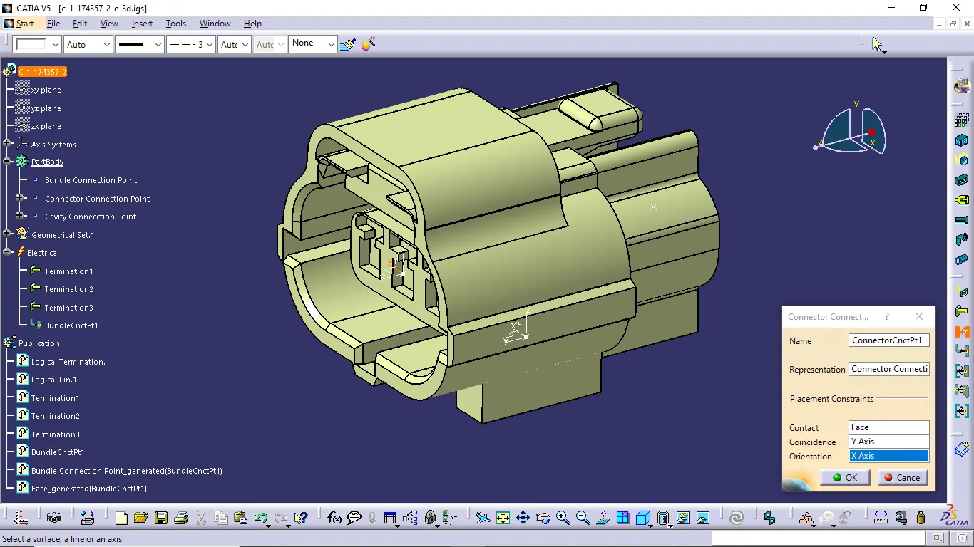
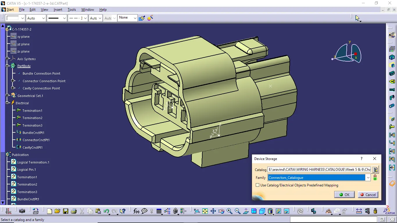
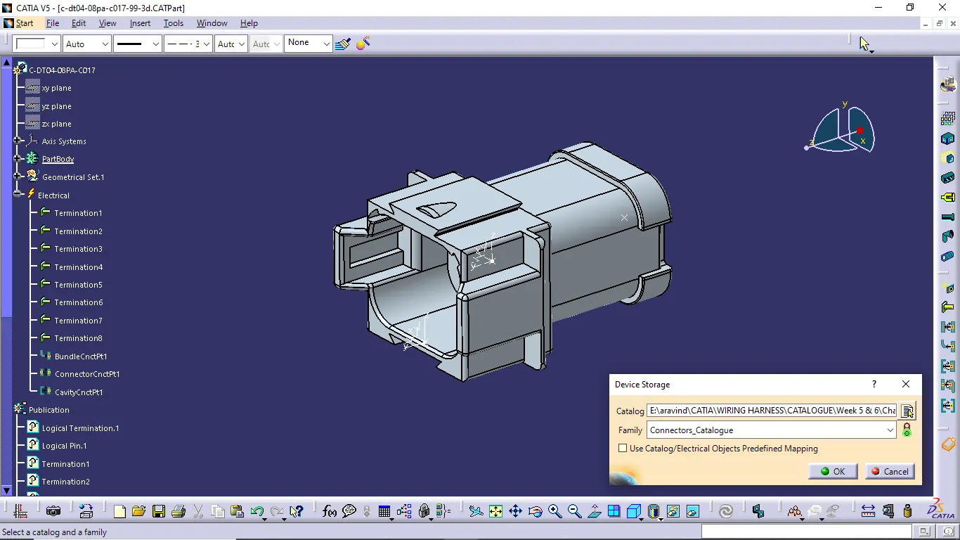
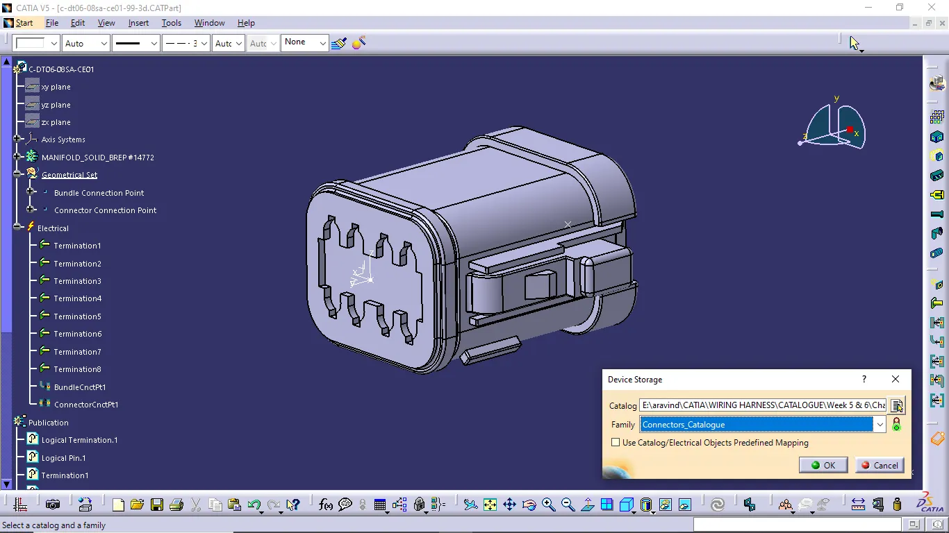
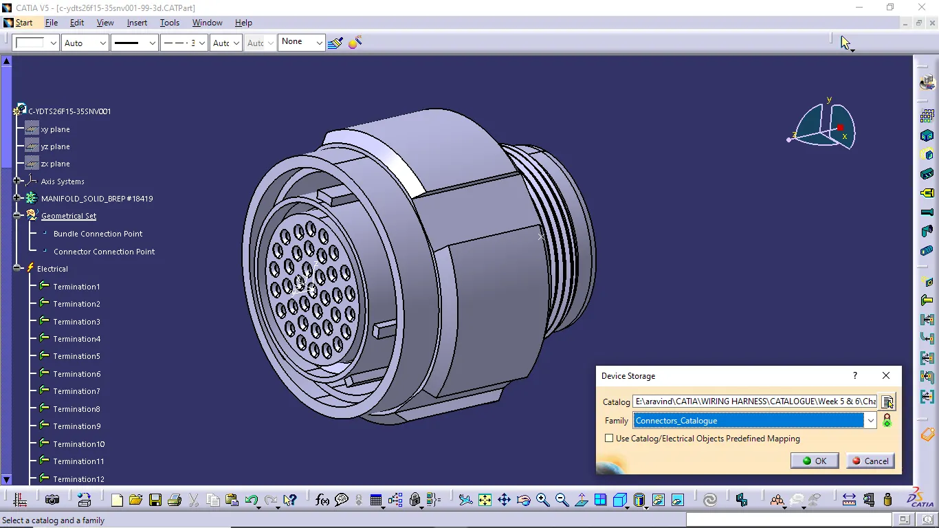
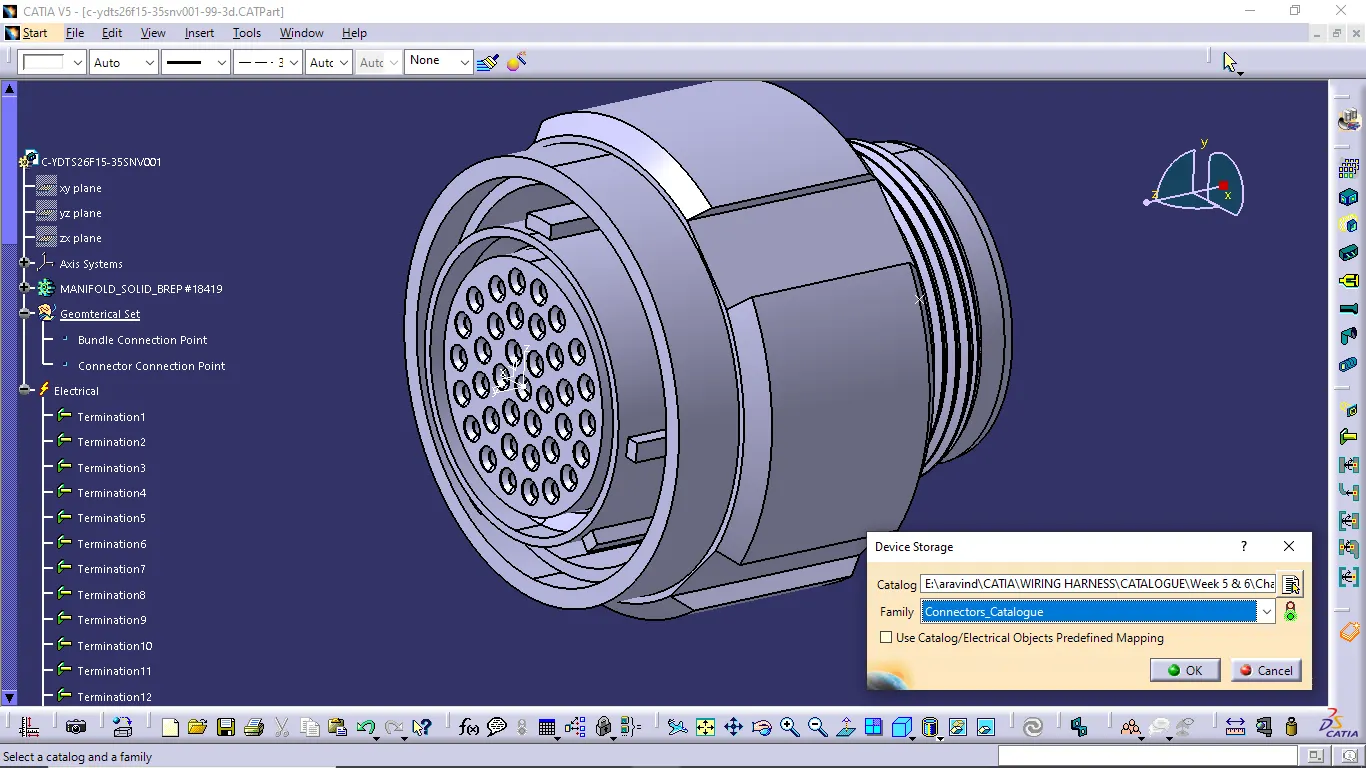
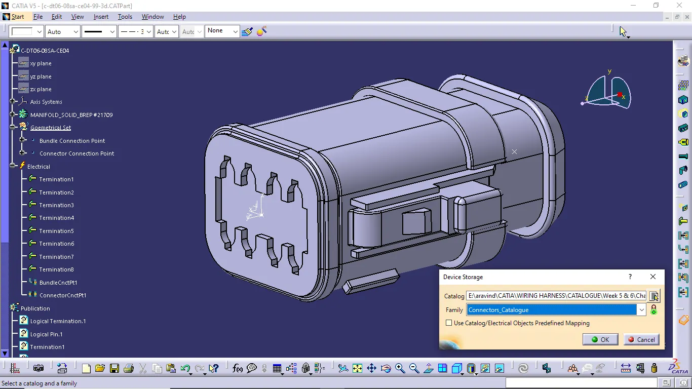
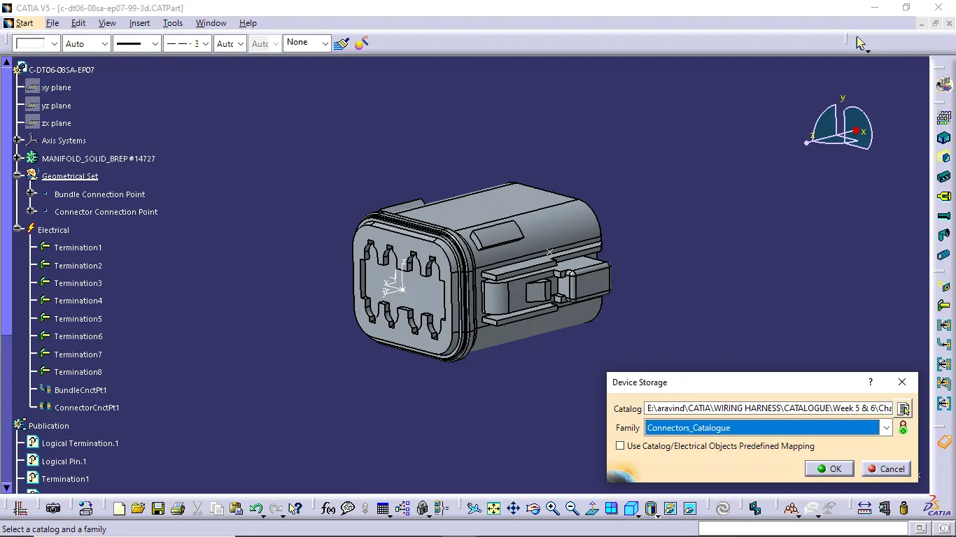
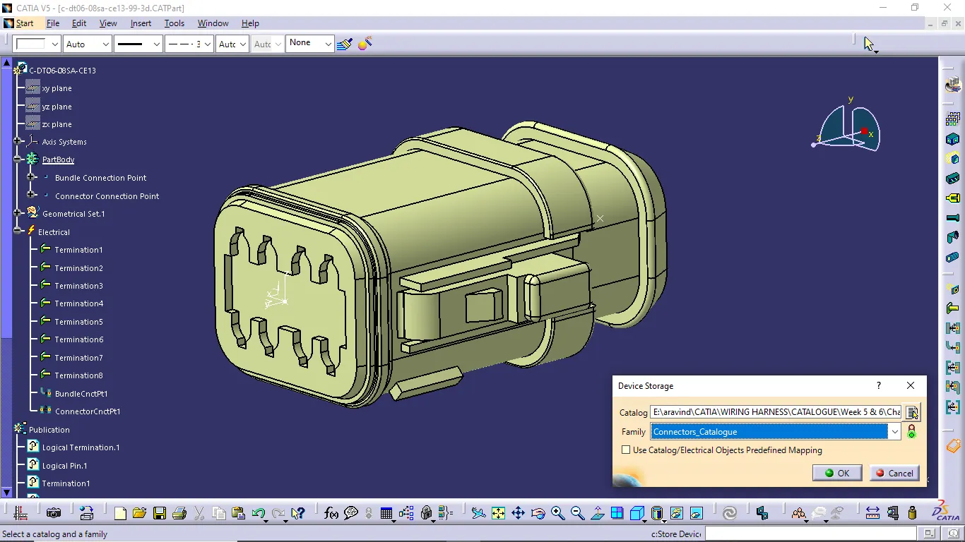
- Add connector to the connector catalogue
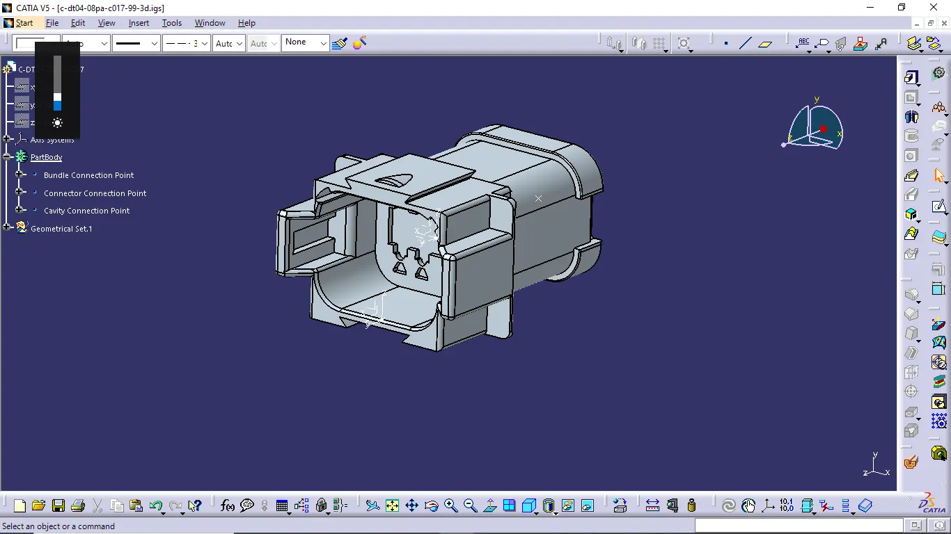
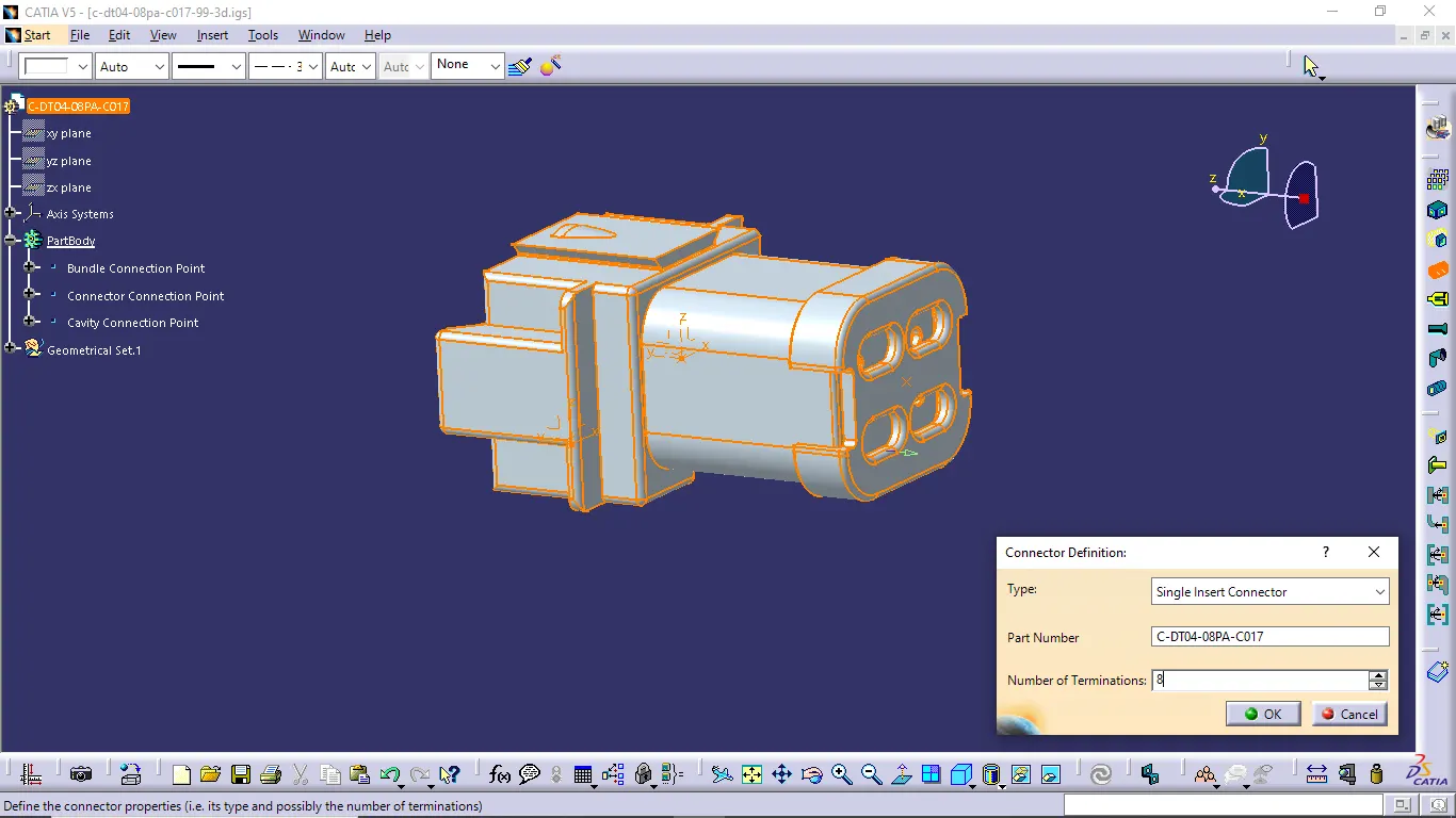
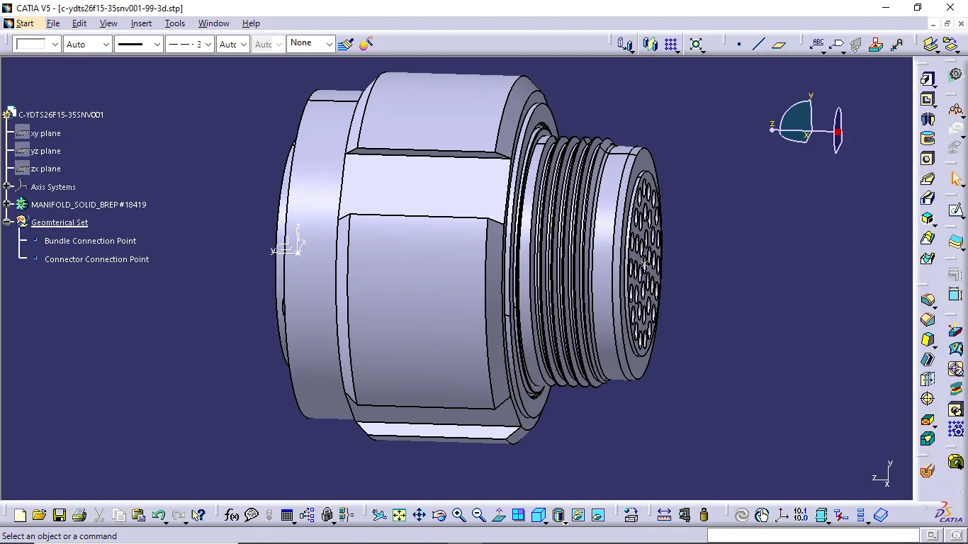
- Do the same procedure to define the connectors electrically and add to the catalogue.
Connector 6:
Connector 8:
Connector 9:
Connector 10:
Connector 1:
Connector 2:
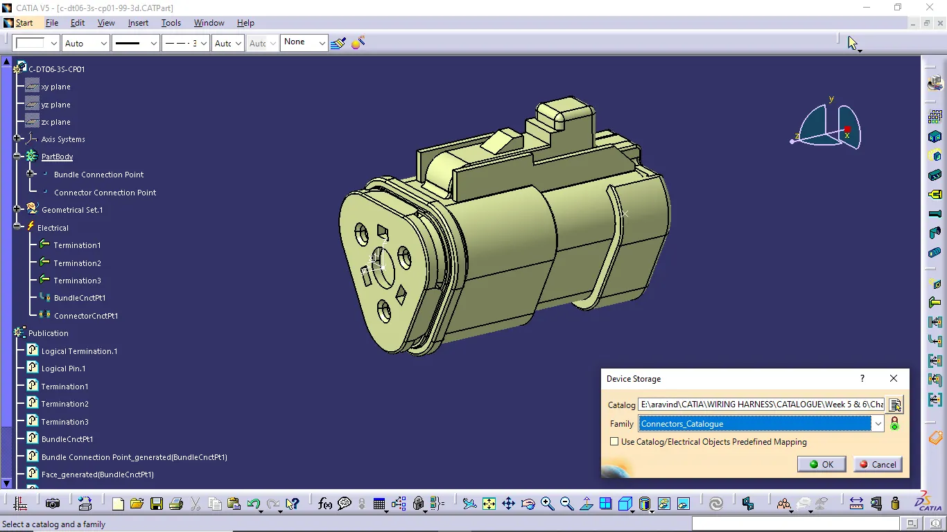
Connector 3:
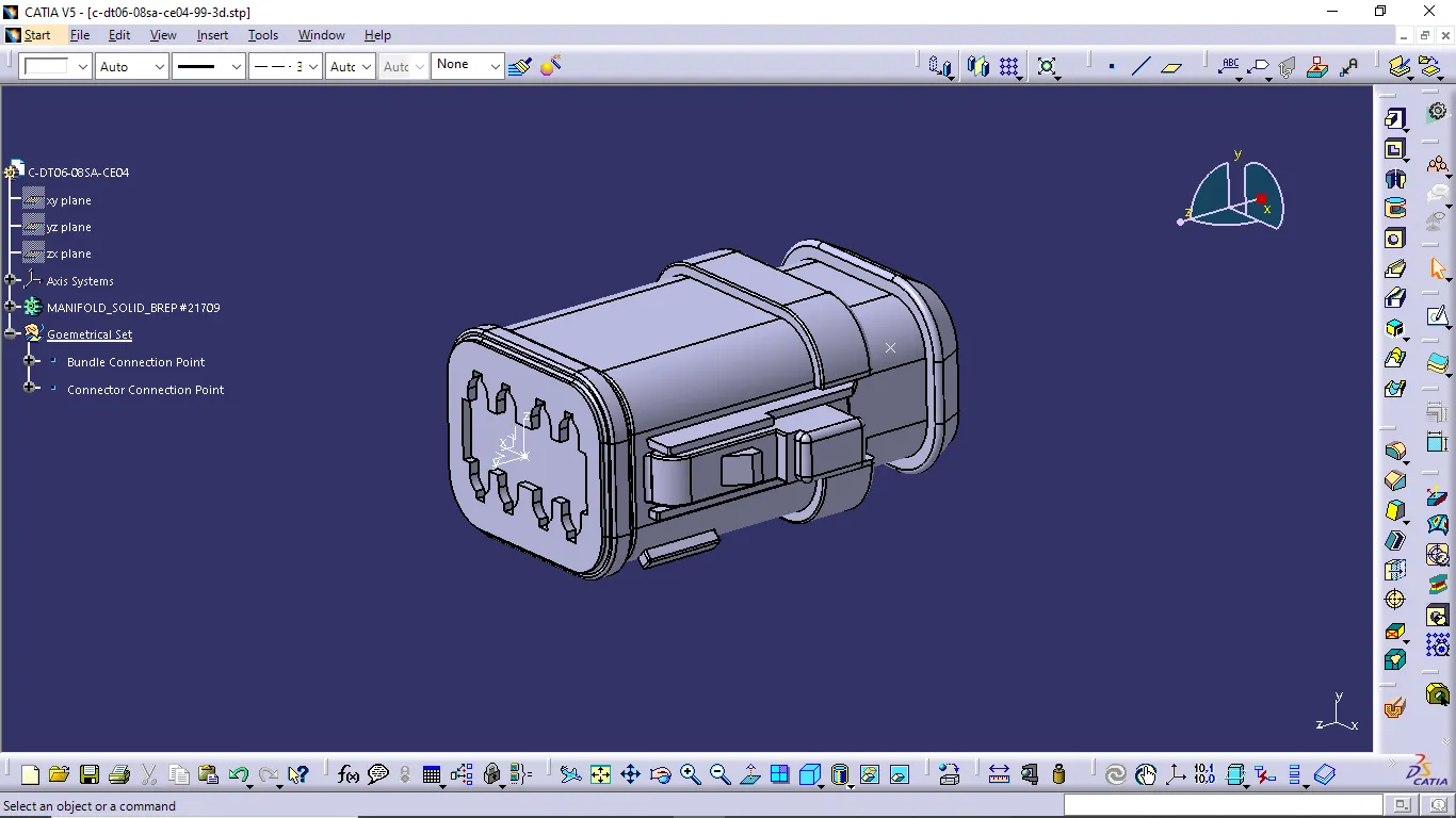
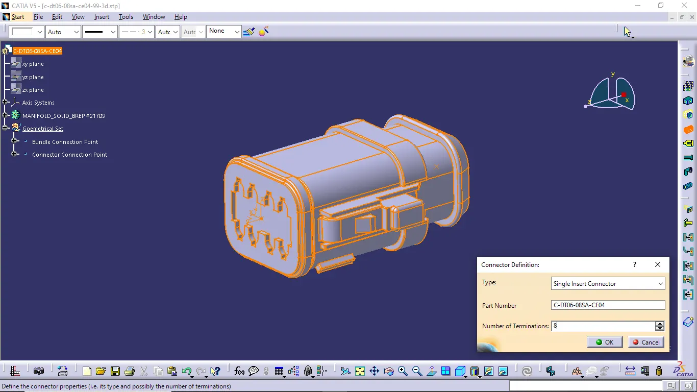
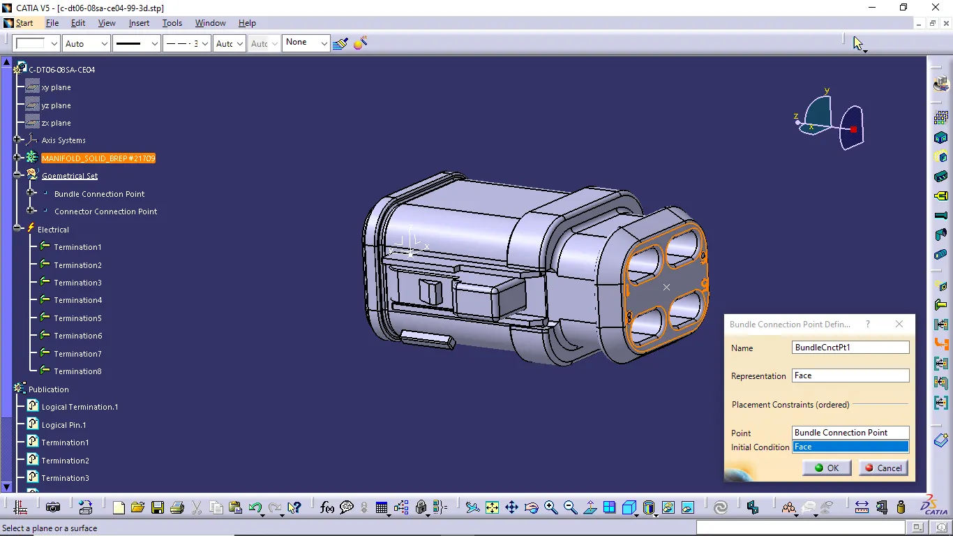
Connector 4:
Connector 5:
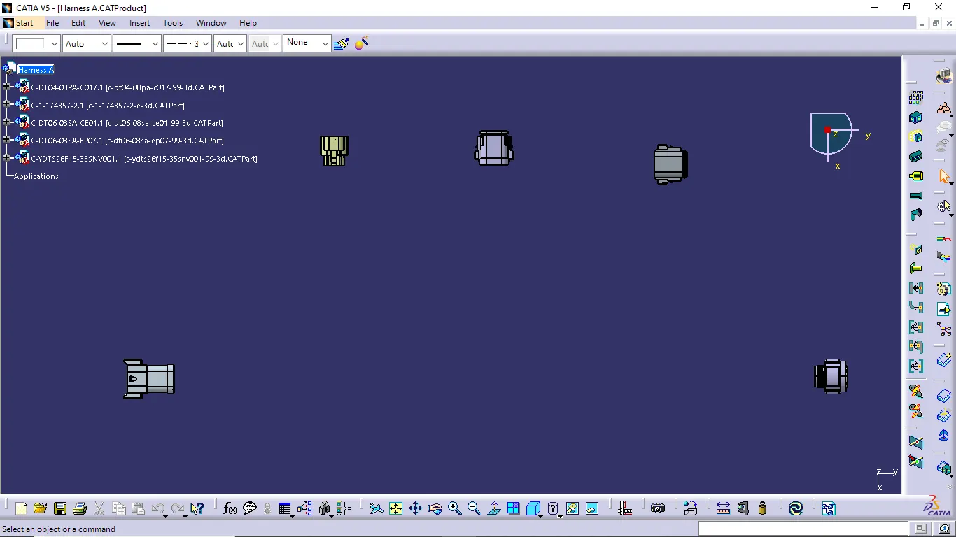
- When completed to define the connectors next we want to create the products like harness A and harness B then positioning the connectors as per the given layout.
Harness A:
Harness B:
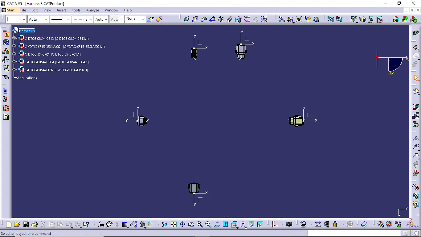
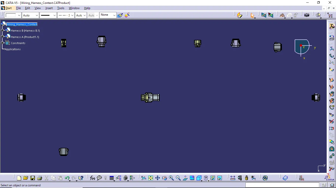
- We completed position of connectors in required places then we want to create the new product as a name of Wiring_Harness_Context and put a Harness A and B product file into this product file.
- When we put the Harness A and B product file into The new product file then go to the electrical assembly workbench and connect the connector 5 and connector 6 using connect electrical devices command.
- Next we go to the separate harness assembly file and do the wiring harness creating process.
Wiring Harness Creating Process:
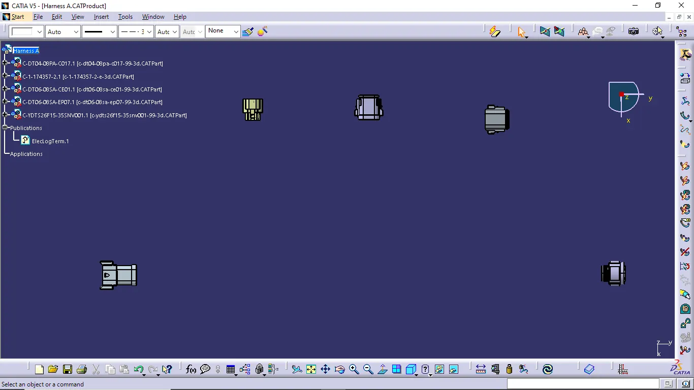
- In the wiring harness creating process first we define the product file as a electrical assemby file using geometrical bundle command in electrical harness assembly workbench.
- When we did the geometrical bundle representation of the product file the publication of Eleclogterm is created.
- Now we do the wiring harness creation for Harness A and Harness B.
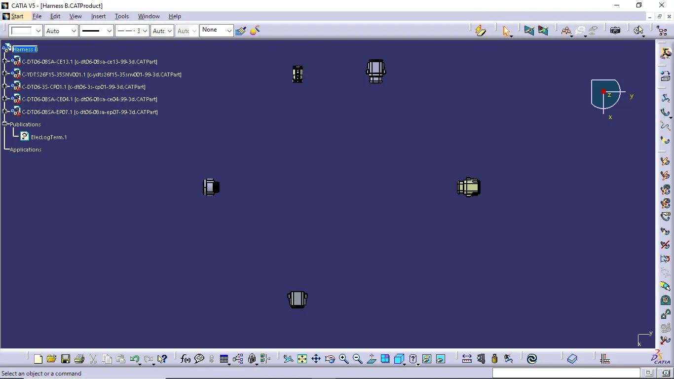
Harness A:
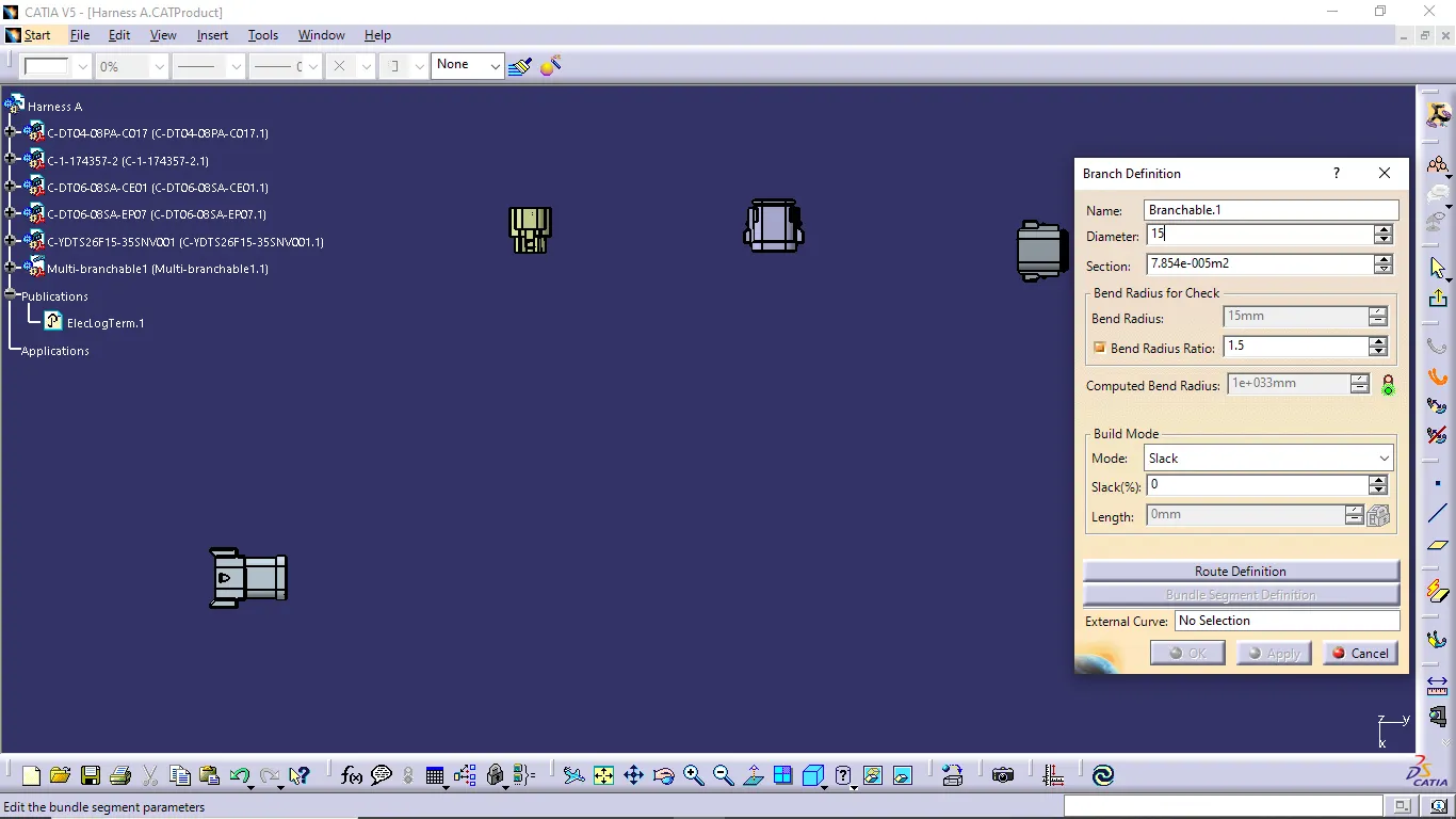
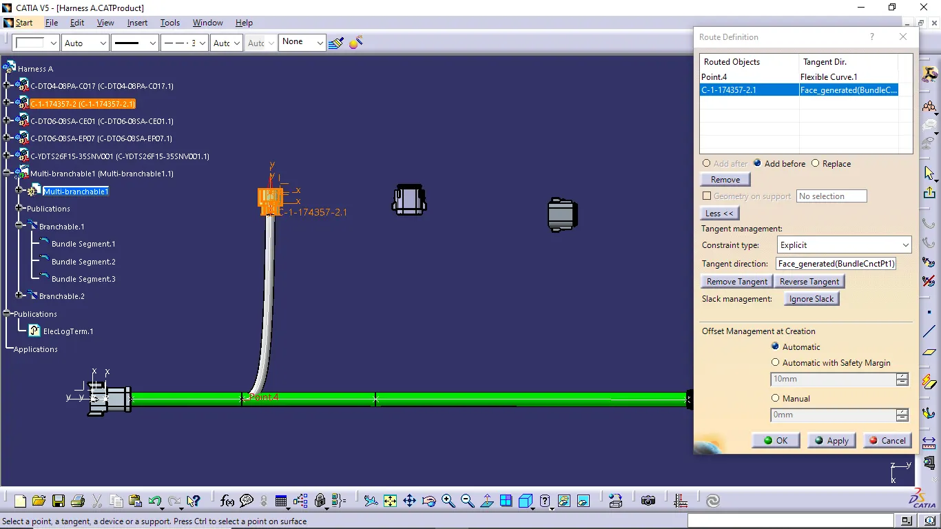
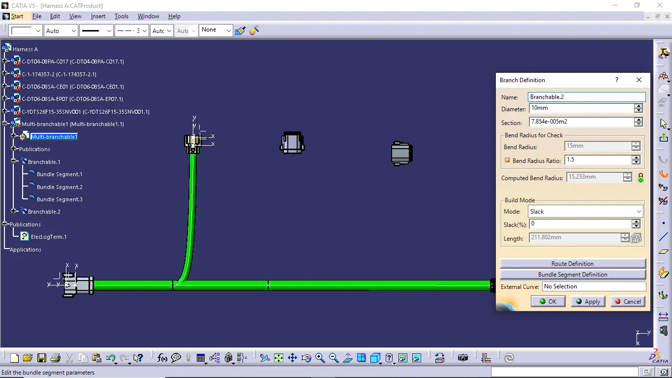
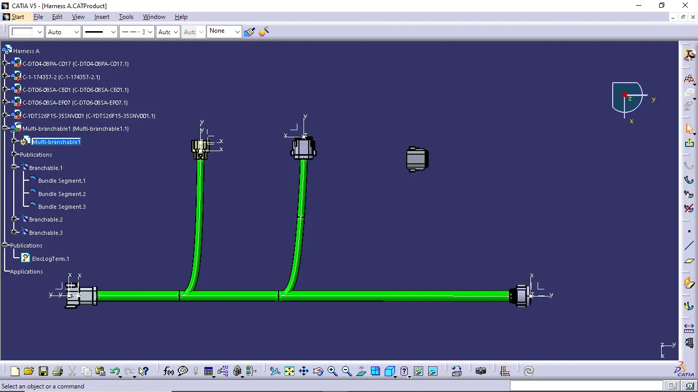
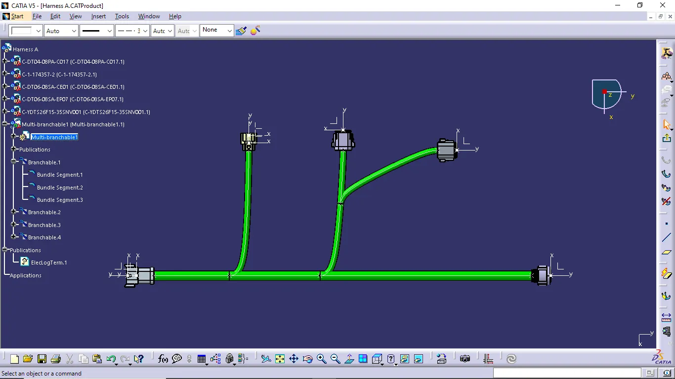
- Now use the multi-Branchable document command to create the wiring harness.
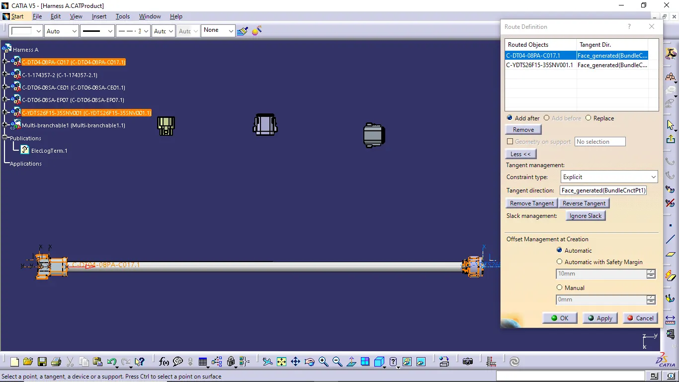
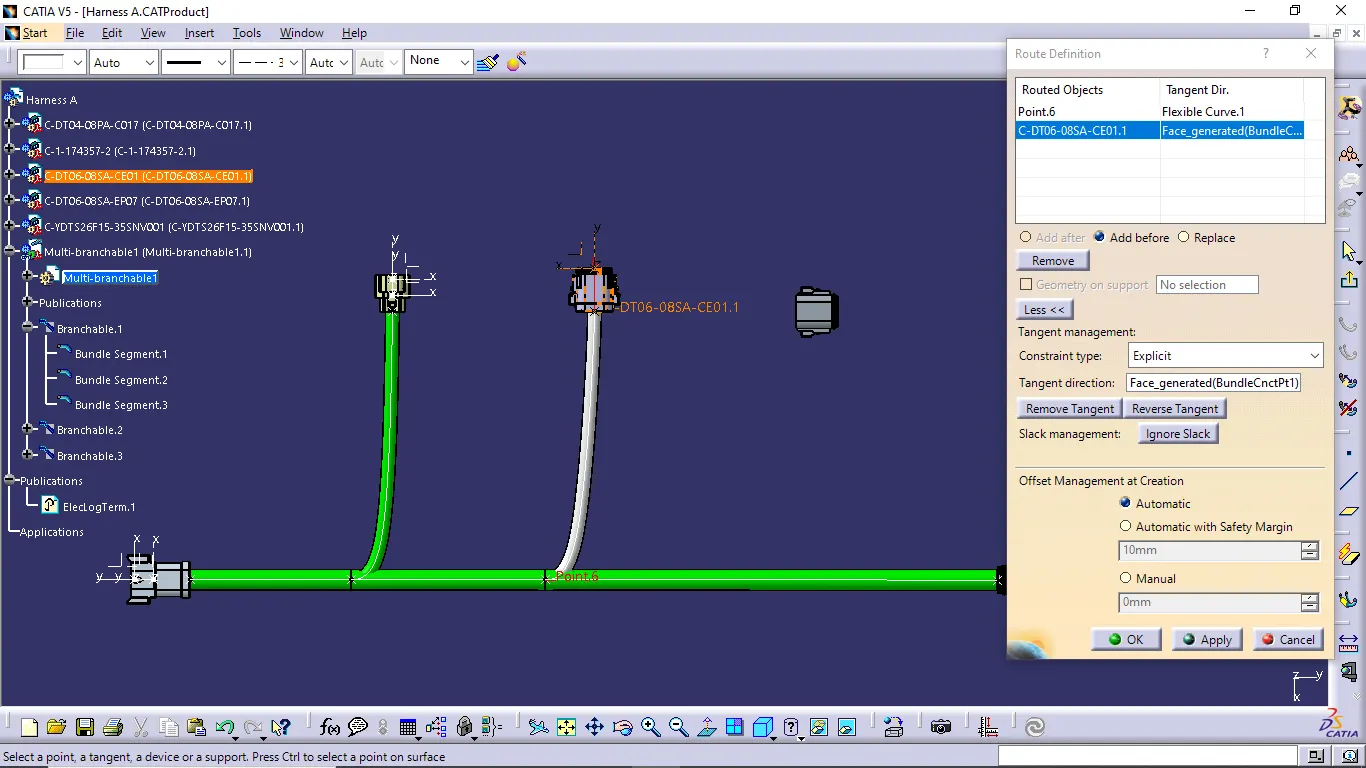
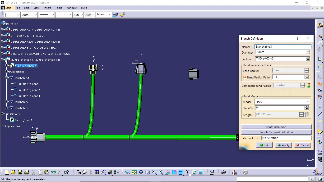
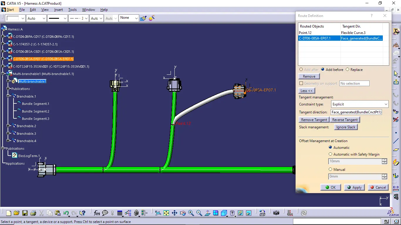
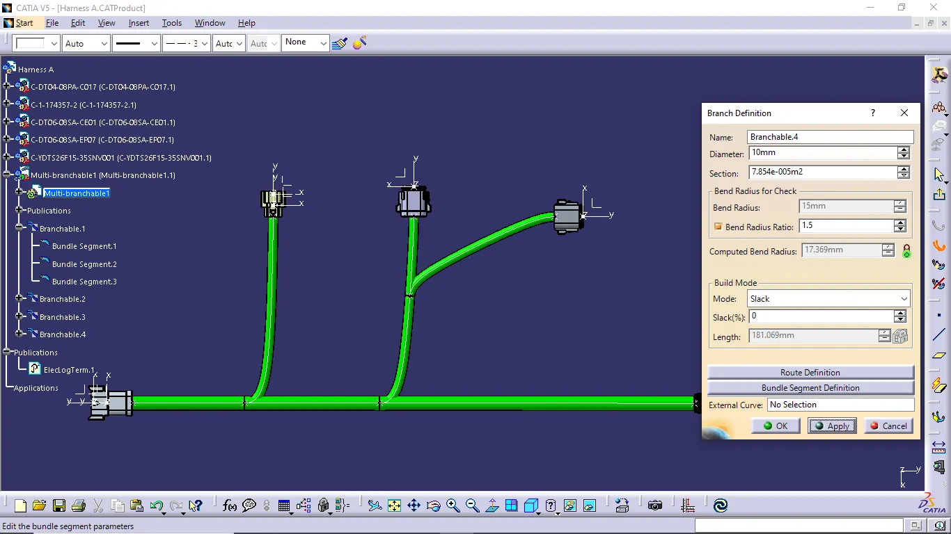
- when we select the Multi-Branchable document command the branch definition dialog box is opened now we give the required measurement of the diameter, bend radius ratio then select the route definition option and select the two connectors if we want to change any details then do it. now we create the wiring harness of two connectors.
- If we want extra length of harness then give the slack details or length increasing method to increase the harness wiring length.
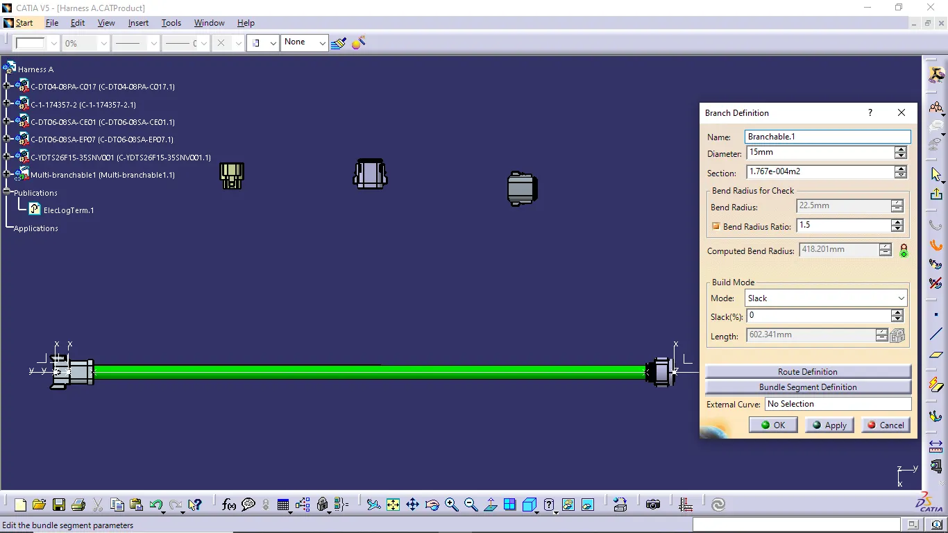
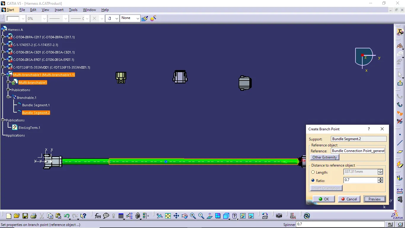
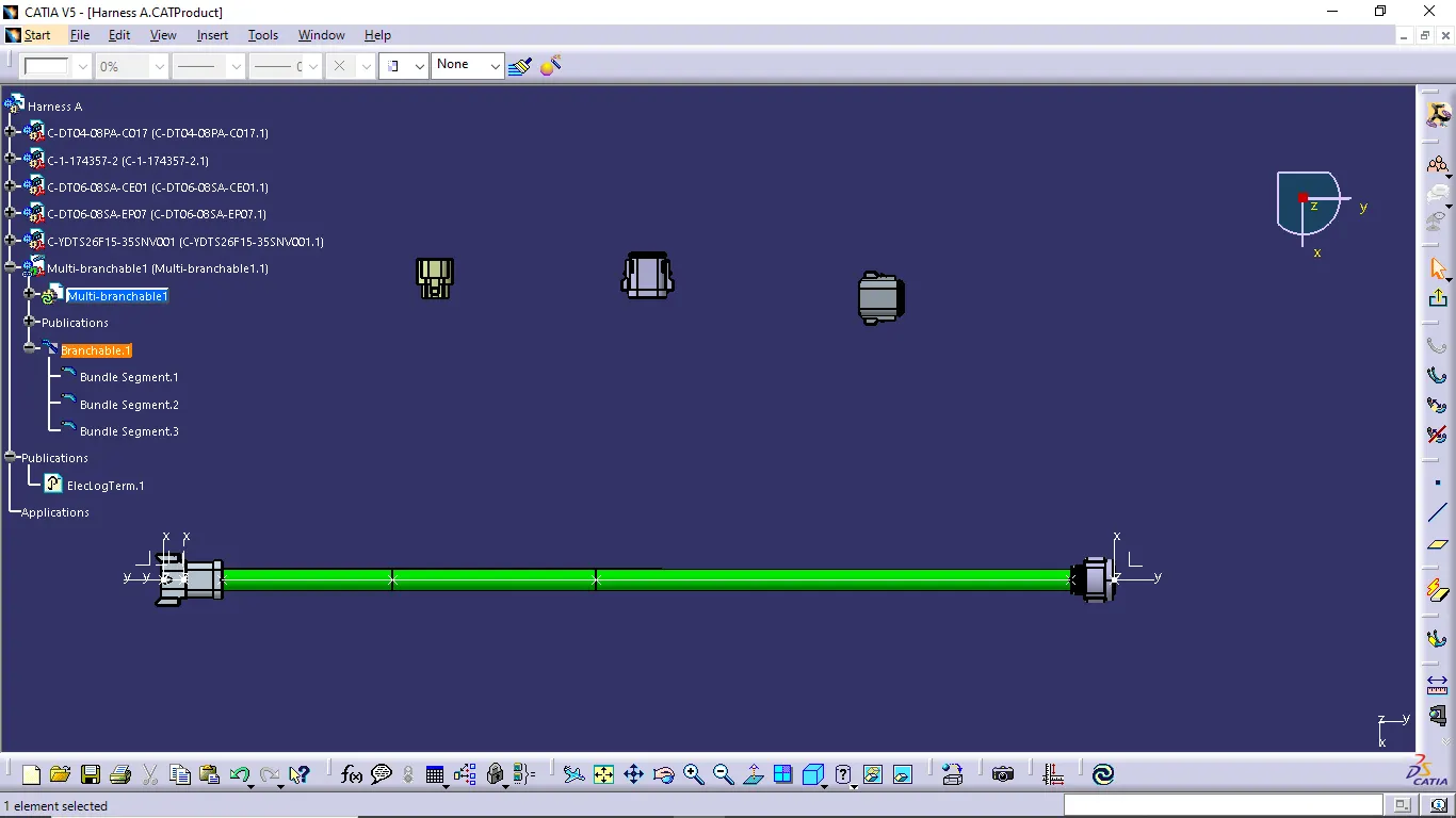
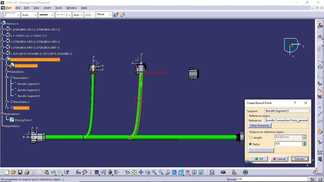
- Then create the branch point of created wiring harness of required position.
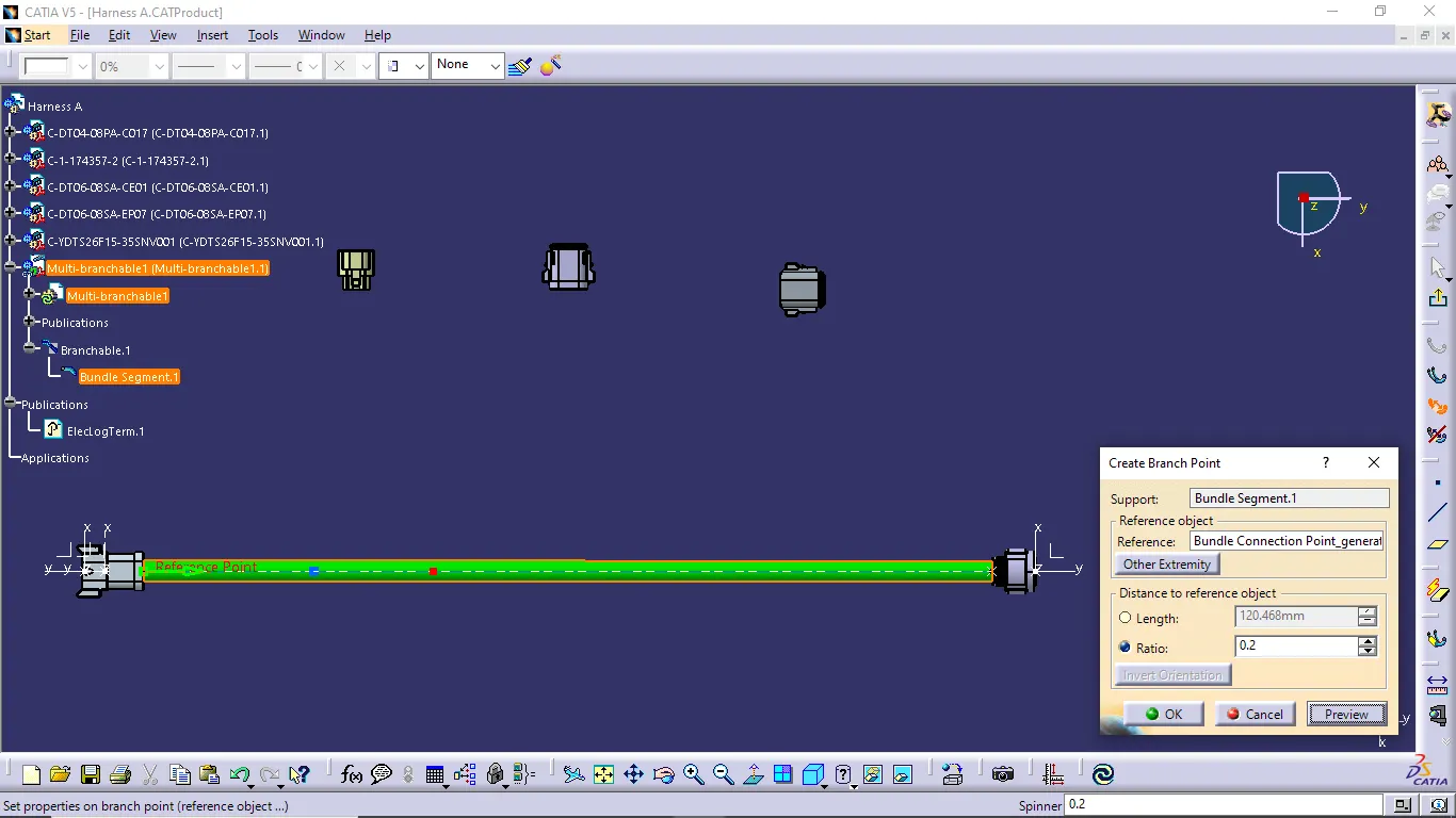
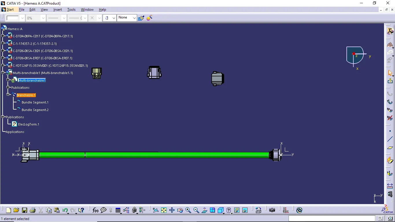
- Do the same process for creating harnesses of all connectors
Harness B:
- Follow the same steps to creating wiring harness of Harness A.
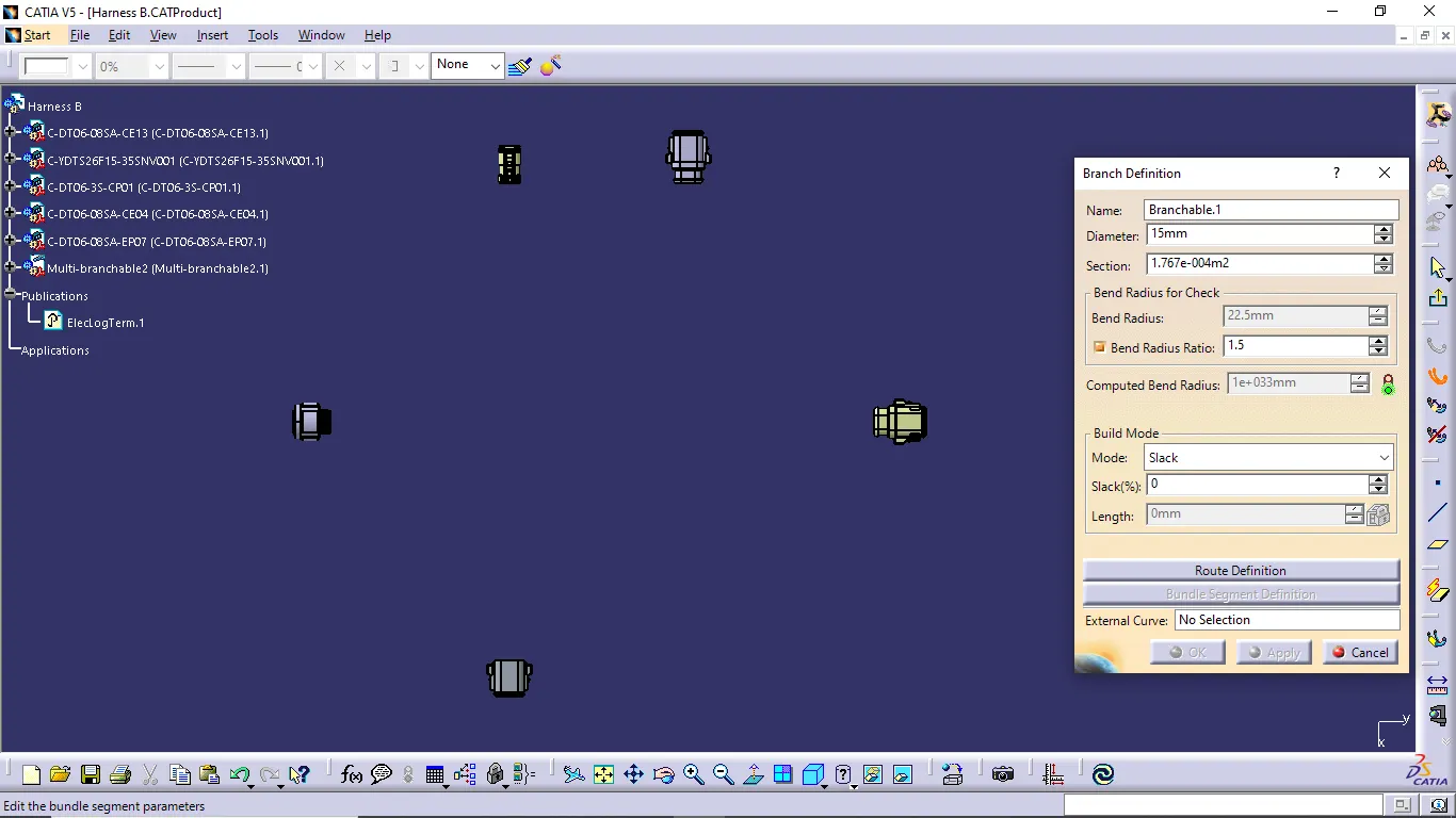
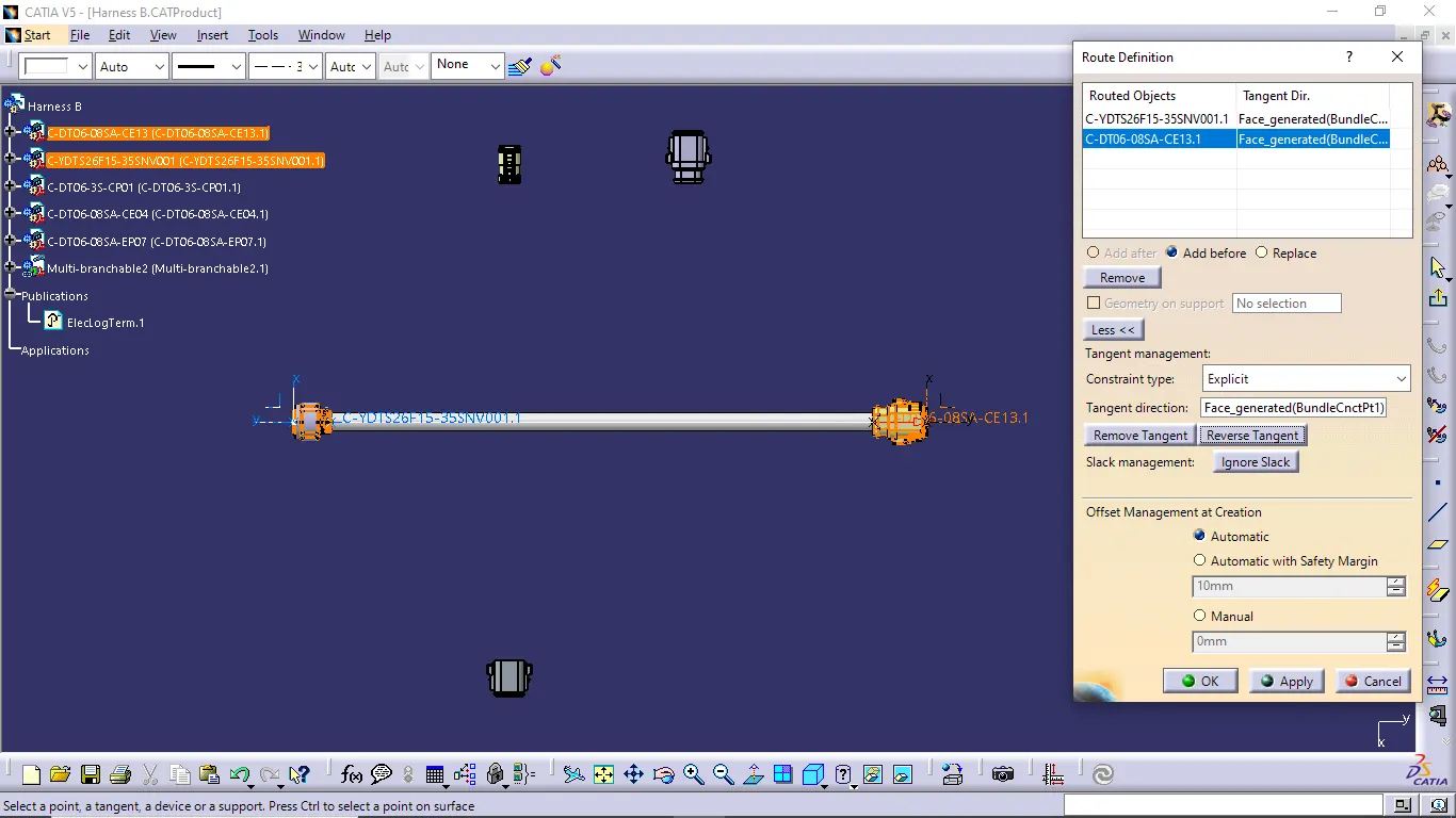
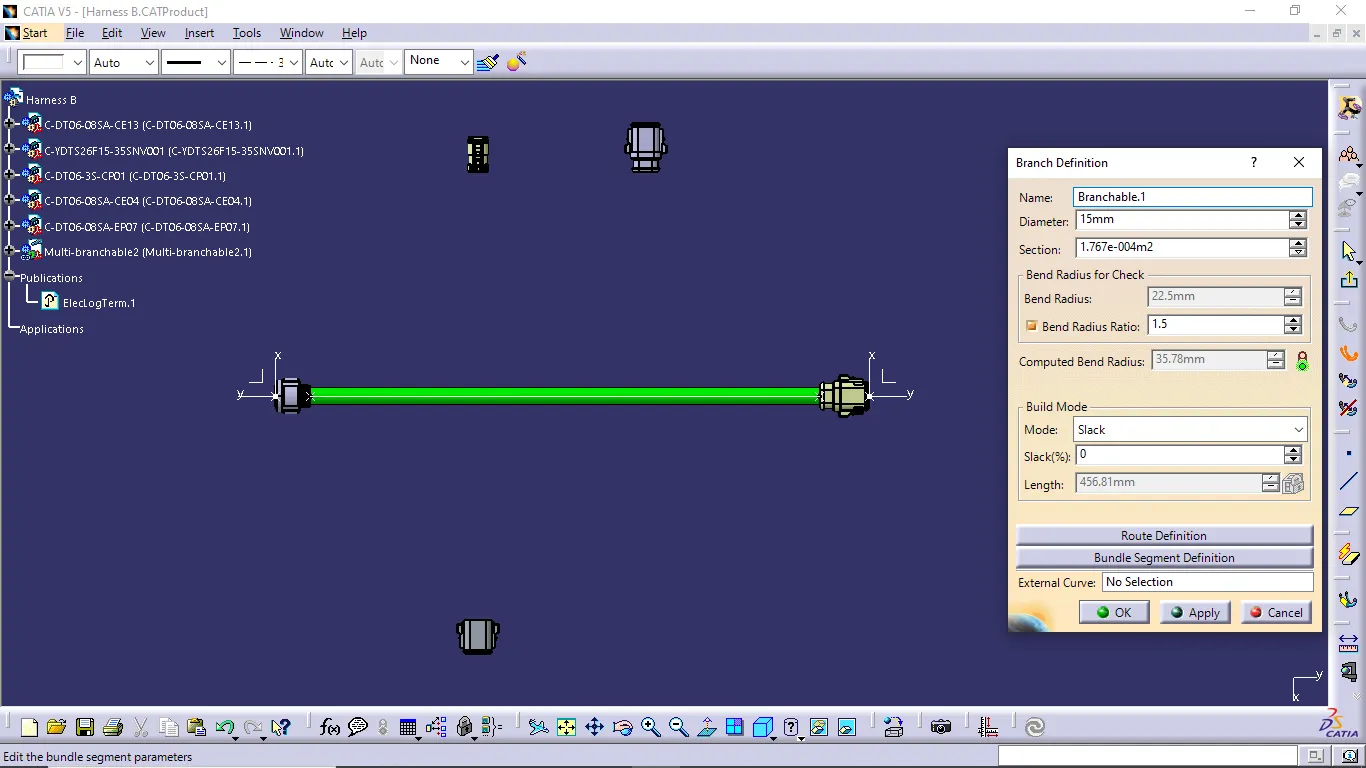
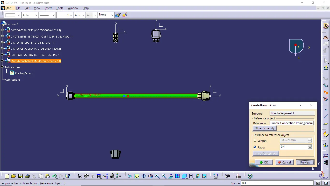
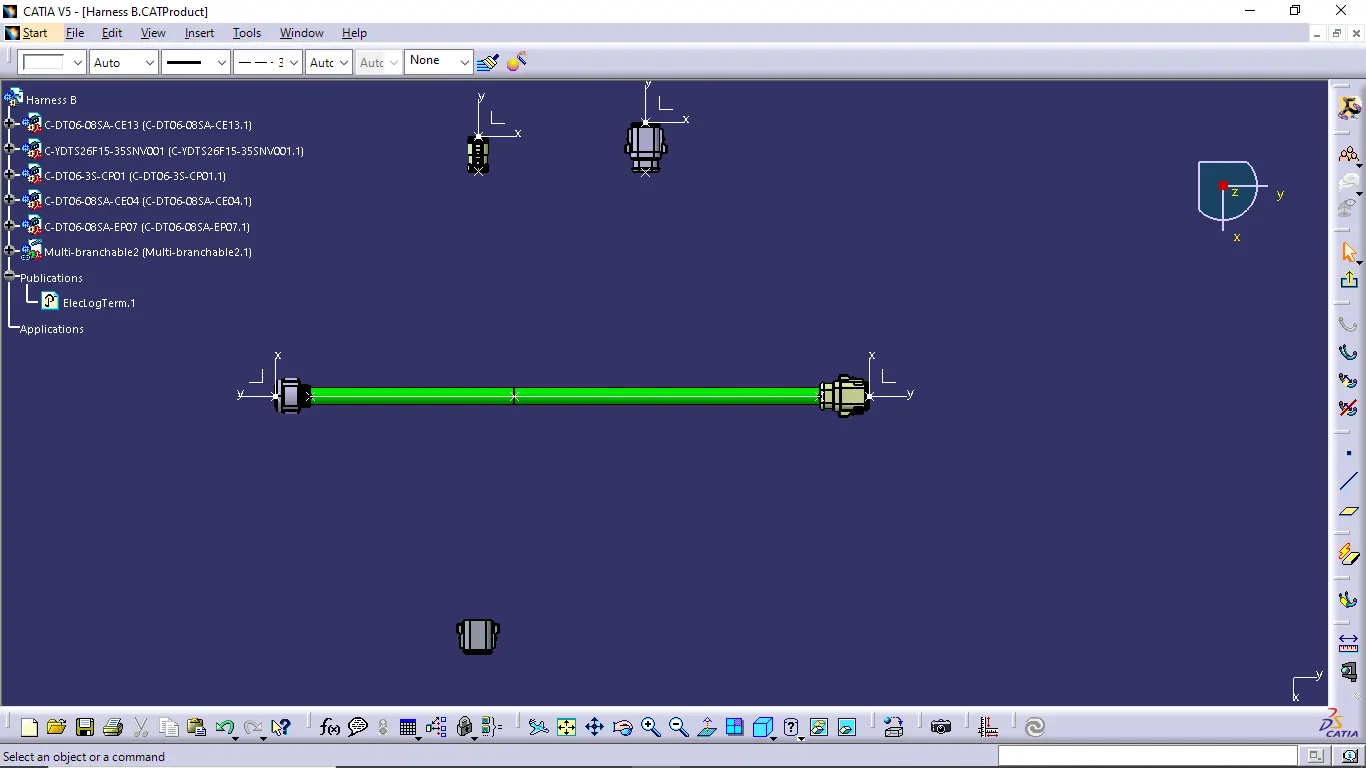
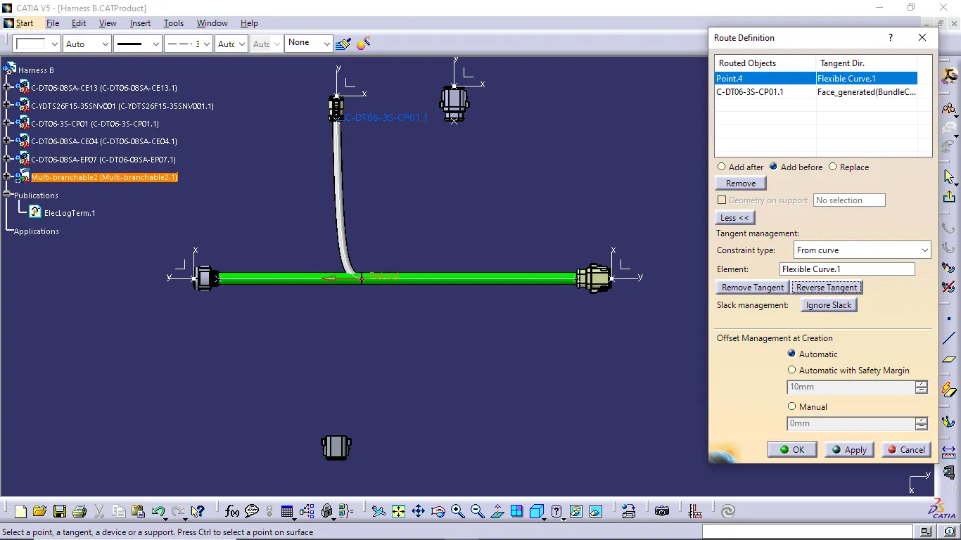
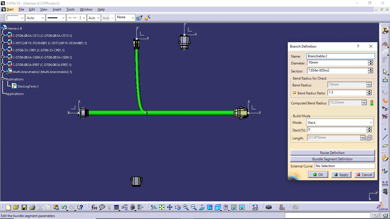
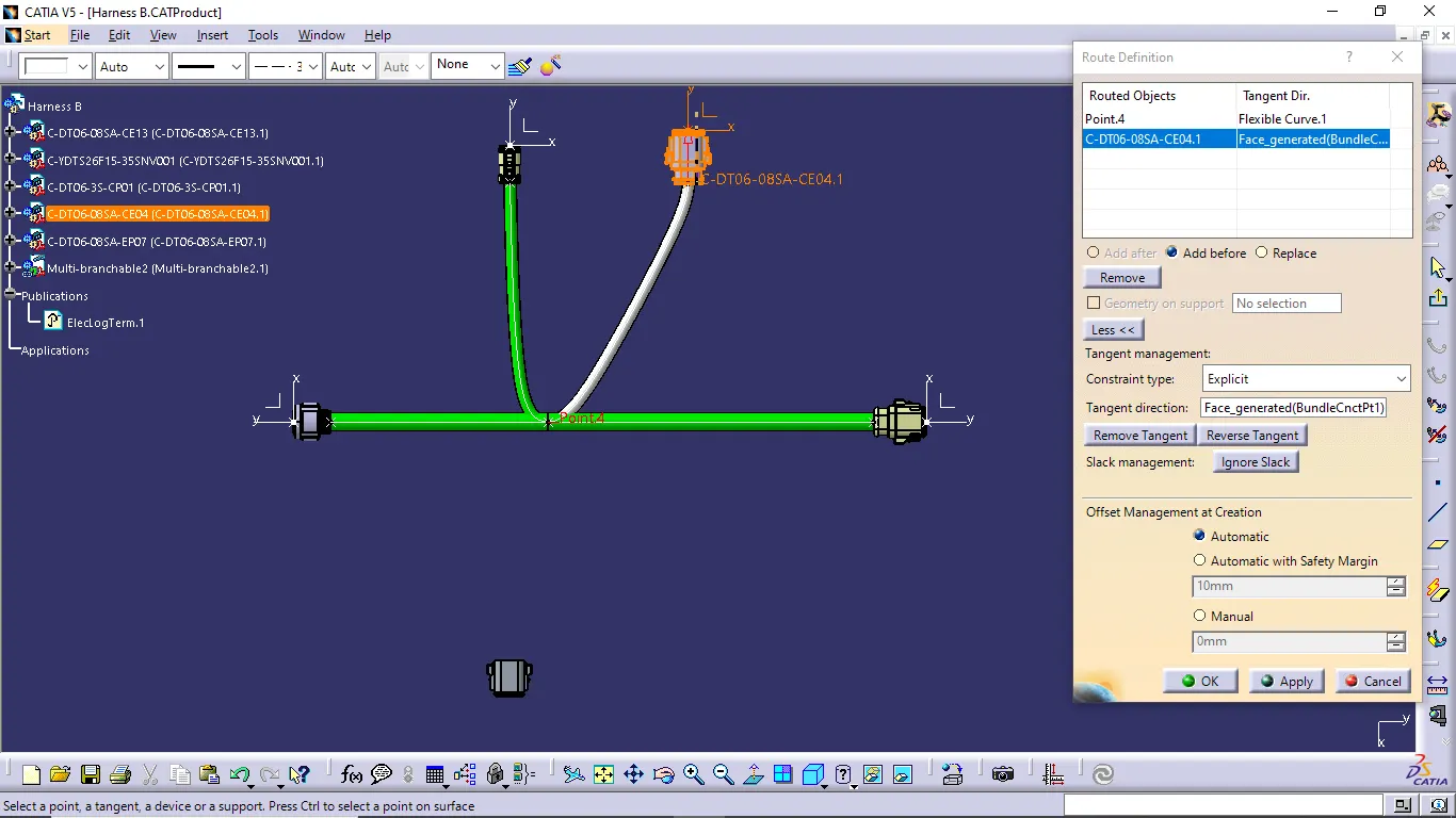
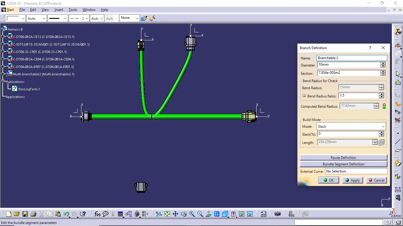
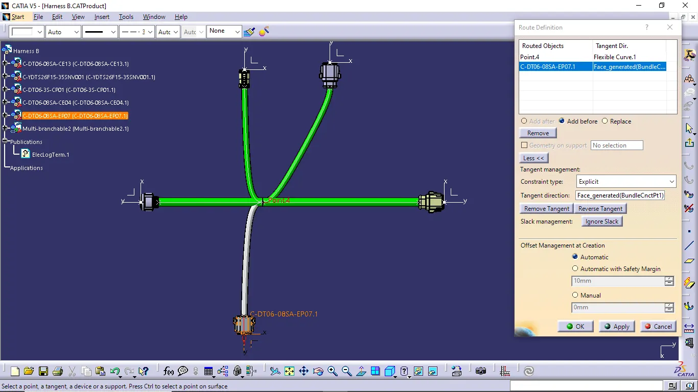
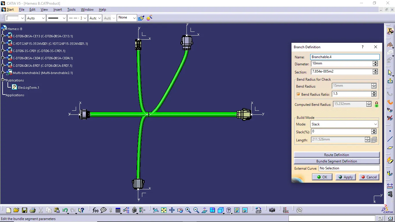
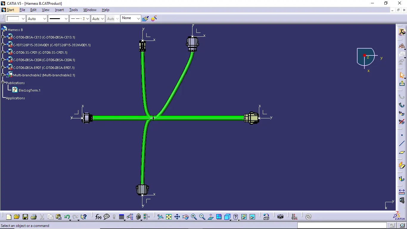
- Finally we completed to create the wiring harness of Harness A and Harness B.
Bundle Warning Checking:
- During the wiring harness creation some time the yellow color is presented in the multibranch file.
- This yellow color indication is presented for the reason of some error is formed during the branch creation of two connections.
- So we want to solve the problem using change in direction of the harness wire connection or change the position of connectors or do the other posible methods to solve the problem.
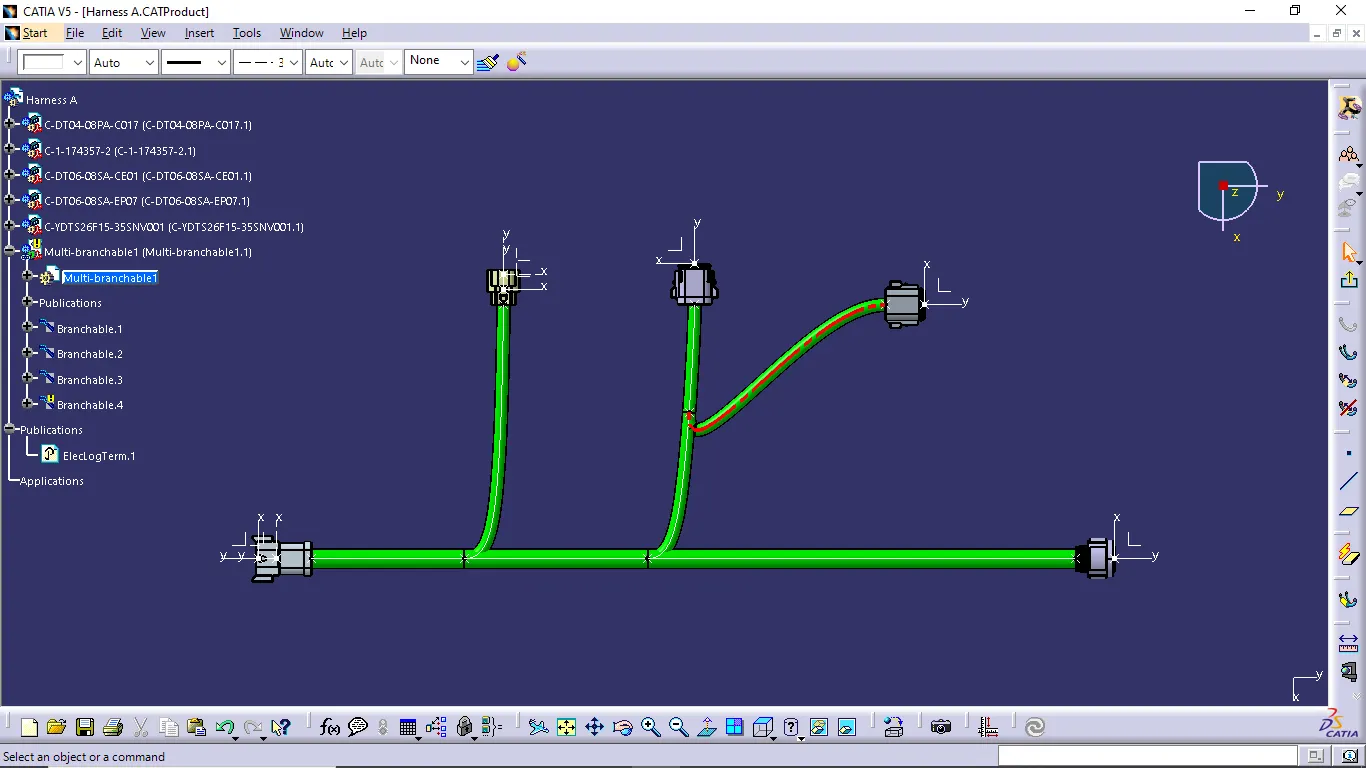
- In the above senario we go to the red curved branch and check the bend radius of the branch first.
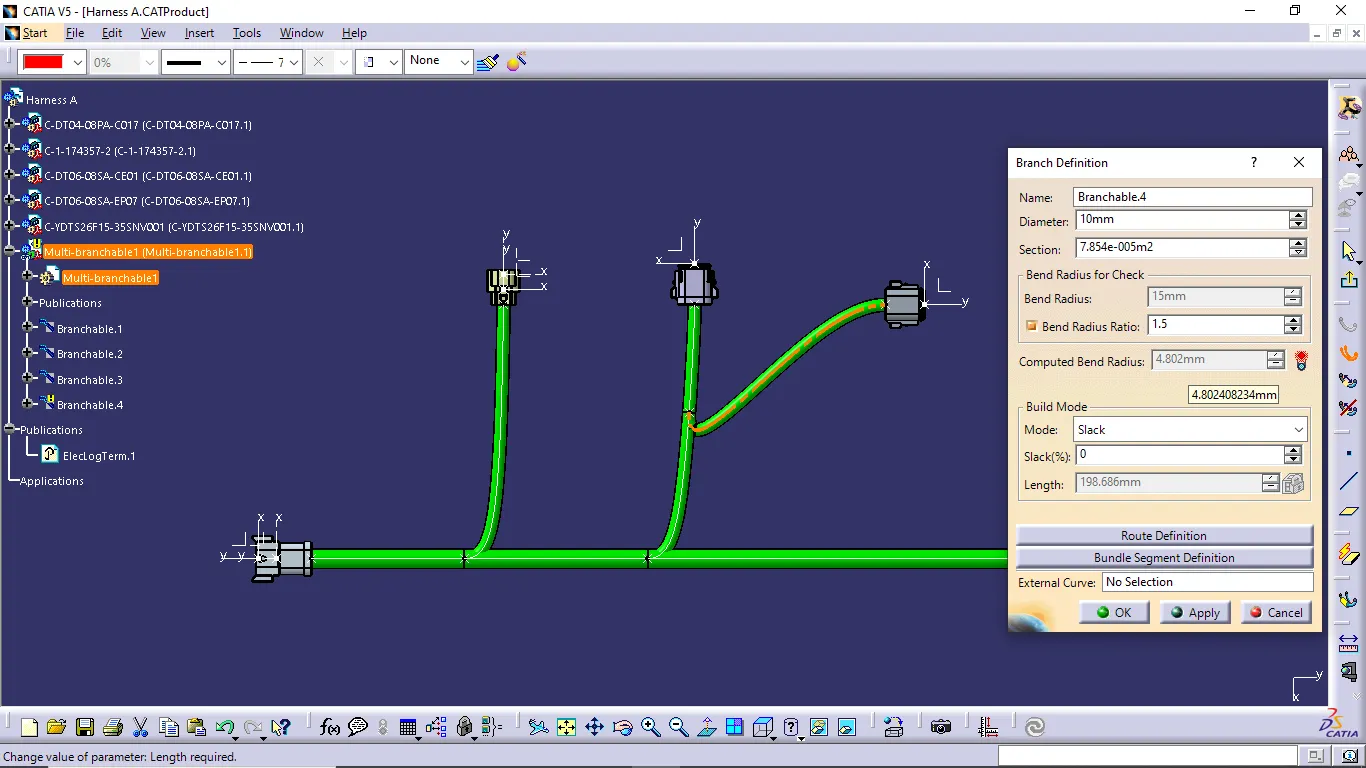
- Bend radius of connection is below required bend radius of 15mm. So, now we want to change the harness wire connection direction to try solve the problem.
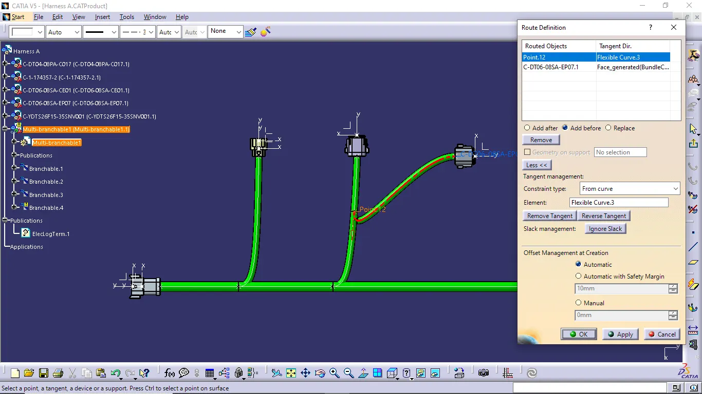
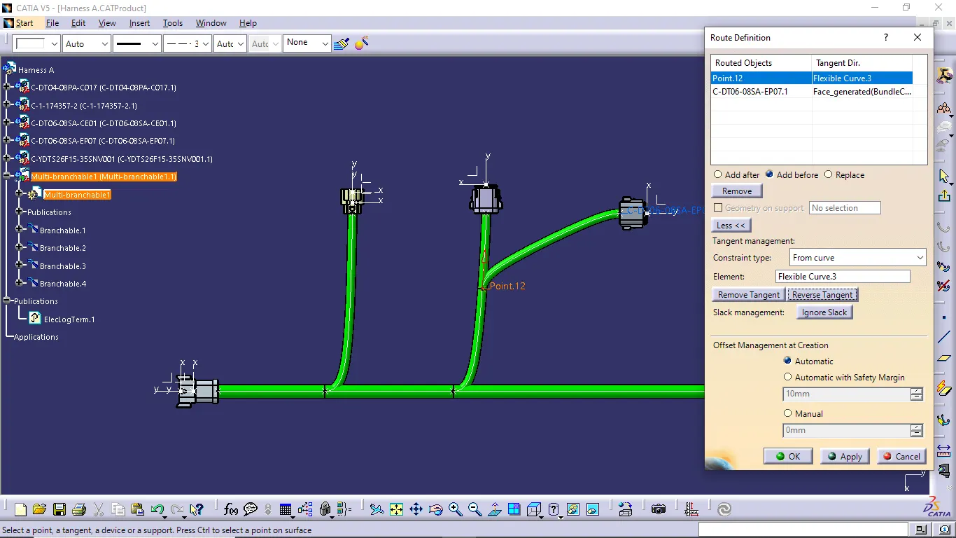
- Now we solve the problem easily using change the direction of the curve.
CHECK BUNDLE CONTINUITY:
- When completing to create the wiring harness of the connectors next we want to check the bundle continuity of the connection.
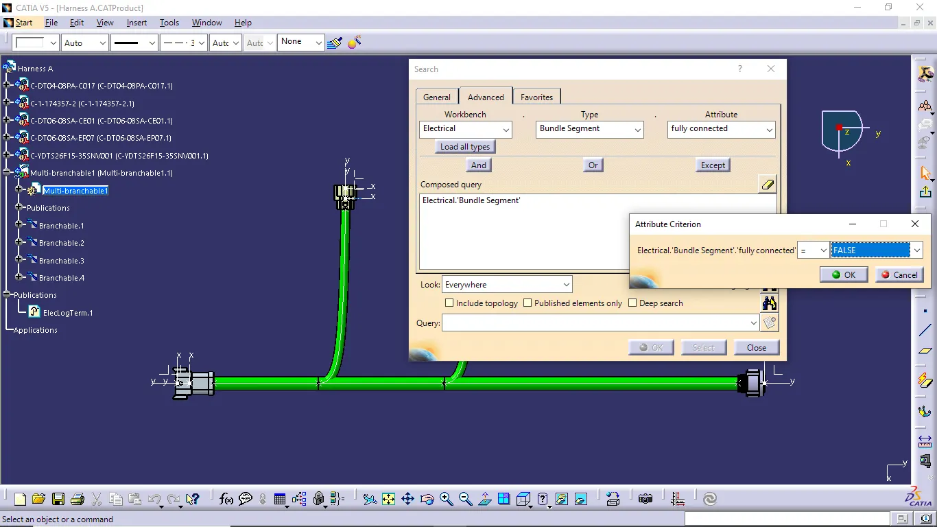
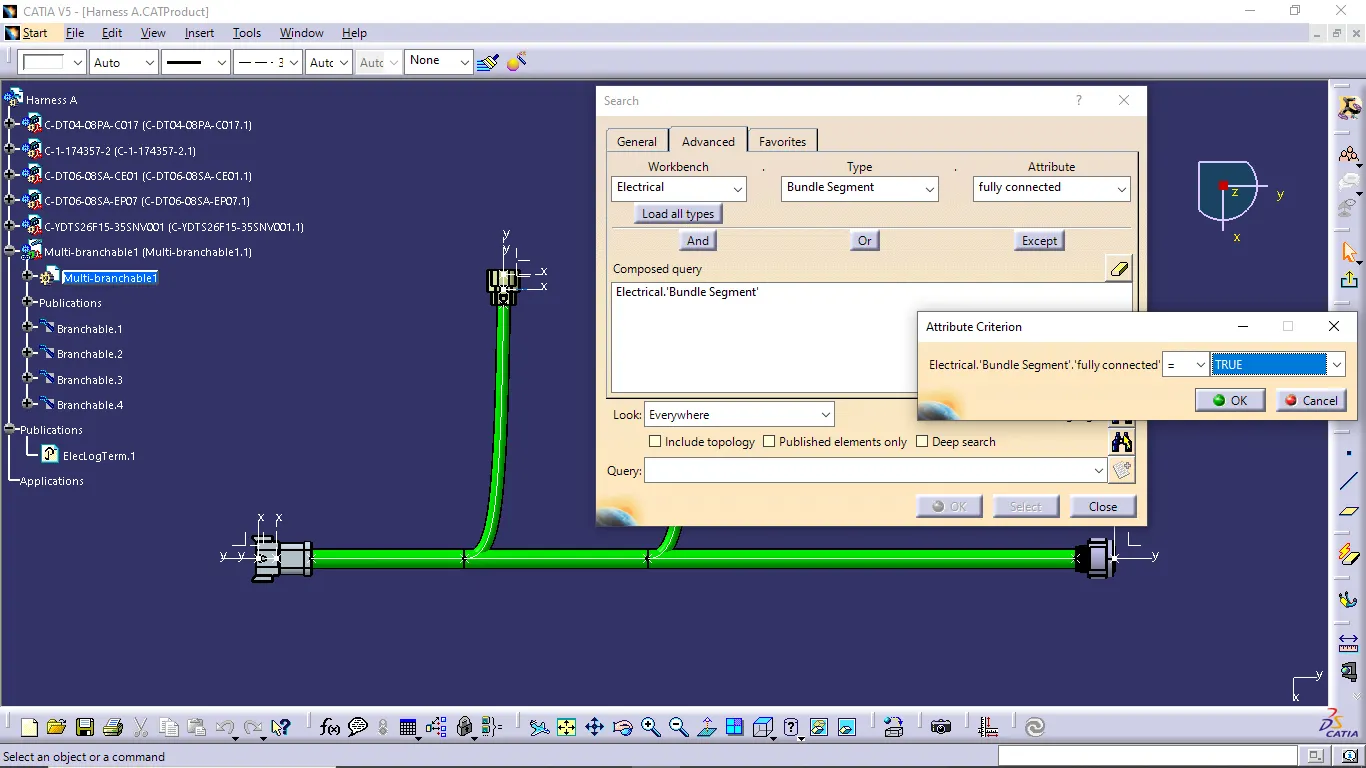
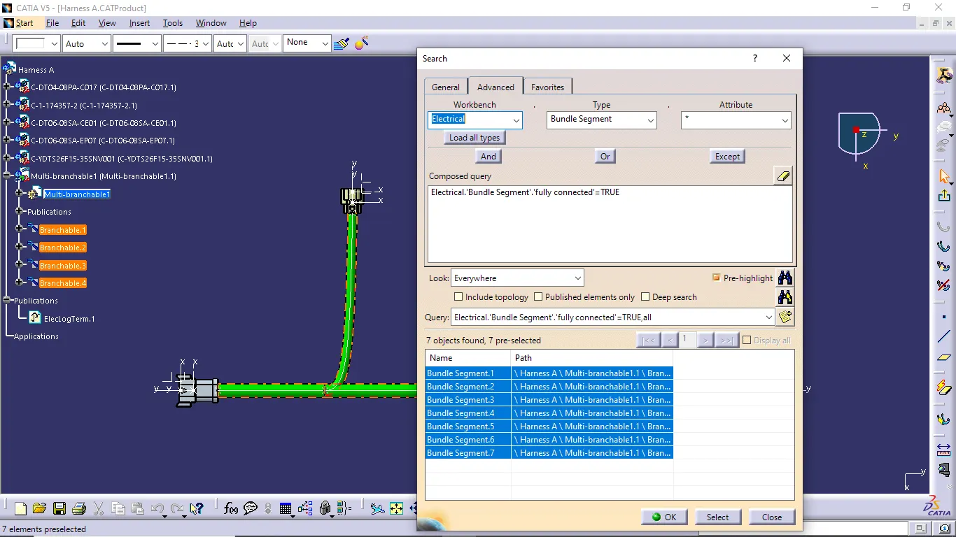
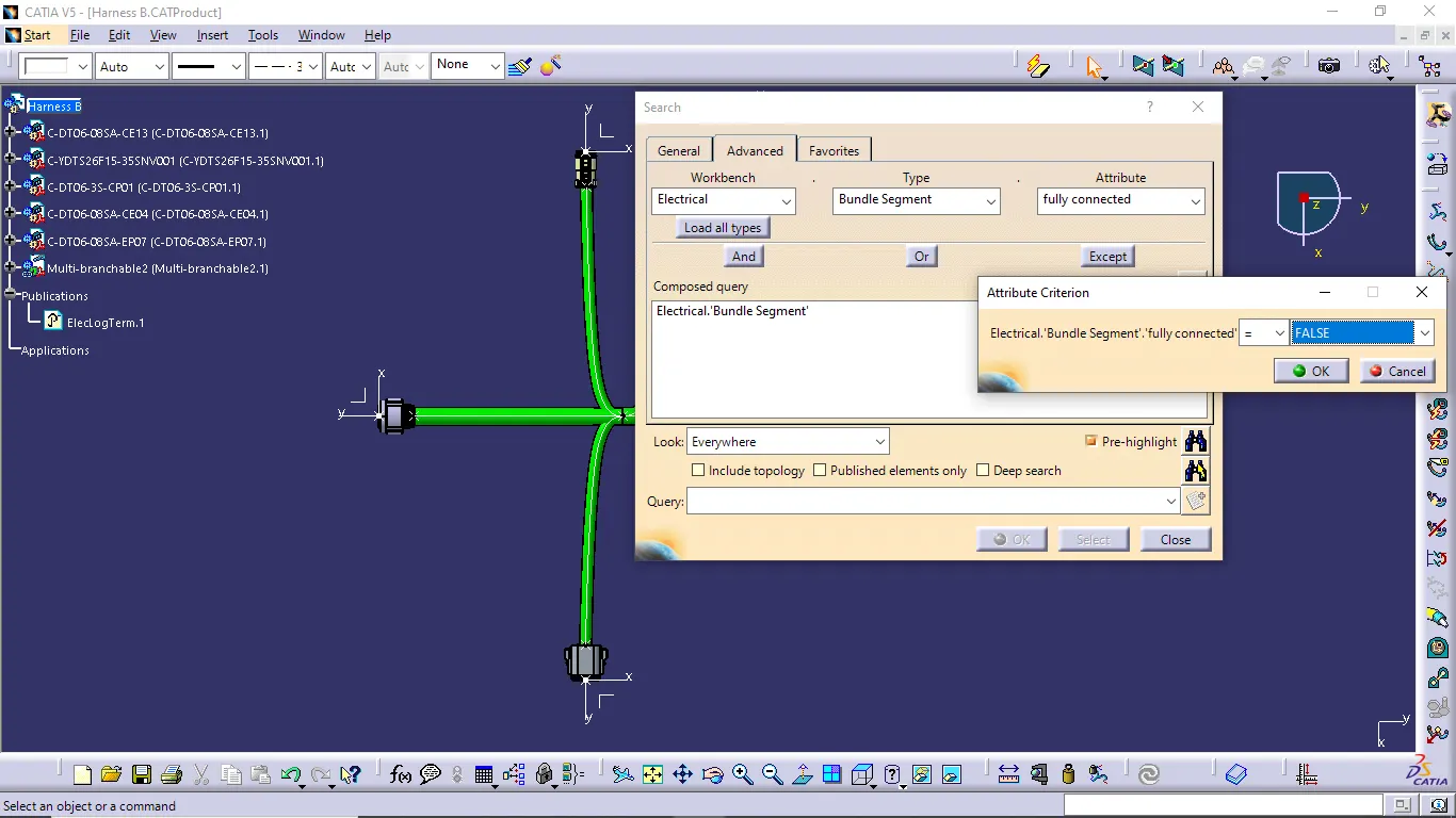
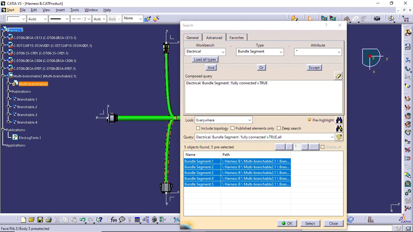
- First we go to the edit section and select the search command. Now click the advanced option then select the workbench as electrical, type is bundle segment and attribute is fully connected.
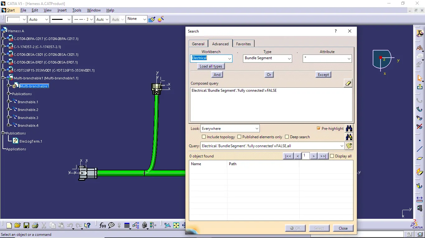
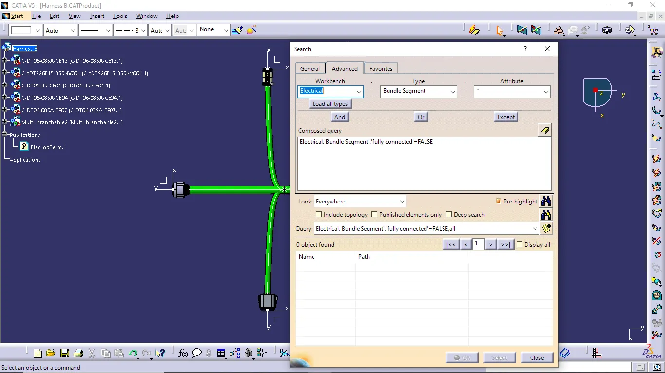
- Now attribution criterion dialog box is pop-up. select first false condition and select the search icon of the dialog box. if any connection is not connected sequencially it indicates to this process.
- If all connection is properly connected no part is specified in this false condition box.
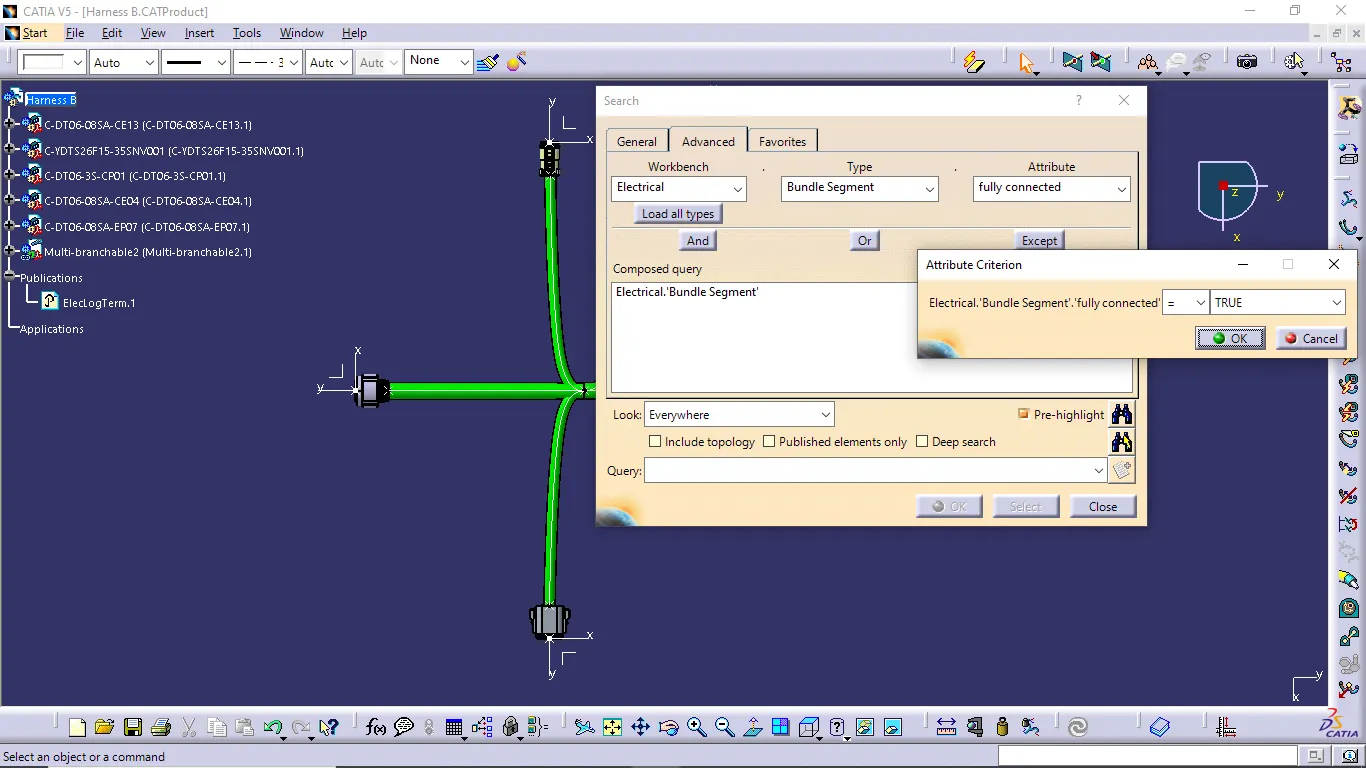
- Next we do the true condition check as same as false condition checking method. but give the condition as true.
Harness A:
Harness B:
ADD ANNOTATION:
- Go to the mechanical assembly workbench and use the annotation tool bar to create the required annotations.
- Select view from reference command and select the front view plane or connector part of the required view.
- Now select the required form of annotation and create the annotation.
Harness A:
Harness B:
GENERATE CAT.part:
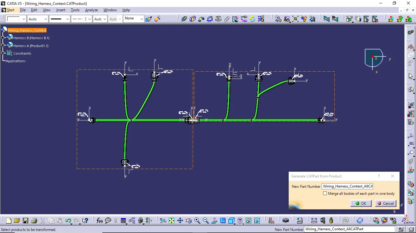
- Now we generate the CAT.part type file for the reason of compatibility of using the designed file for another different software users.
- Part file some time changing for the another design softwares so we converted into CAT.part type file and save as IGS file format also.
- While generate CAT.part file first we go to the mechanical assembly design workbench and then go to the tools option and select generate CATPart from product command then give the new part number click ok.
- Now we convert the product file into CATPart file.

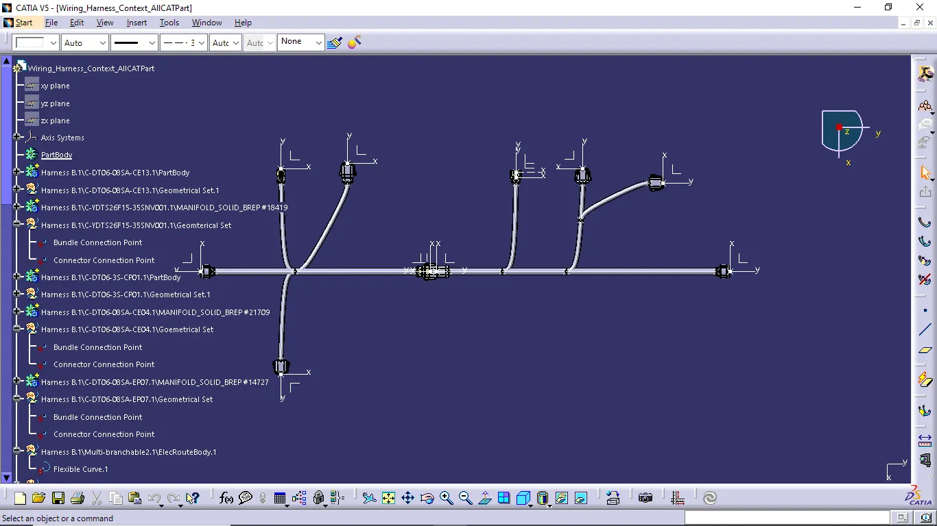
- Now we easily convert the CATPart file into igs format file.
CONCLUSION:
Finally i completed to routing the given connectors as per the given layout and also complete the given objectives.