Wiring harness design in CATIA V5 - 3D modeling Week 5 & 6 Challenge
Wiring harness design in CATIA V5 - 3D modeling Week 5 & 6 Challenge:
<!-- x-tinymce/html -->
Aim:
- Route the harness design for given layout.
- Then check the continuty between the bundle.
- Add the annotation to all connectors.
- Check the bundle warnings and convert overall product file into .CAT part file and convert that into the .igs formate.
Introduction:
In this challenge .we are going to see the how to create and connect multiple branching points,tangency management,routing with external curves,bundle continuty check/analysis,geometrical bundle warnings and 3D annotations.
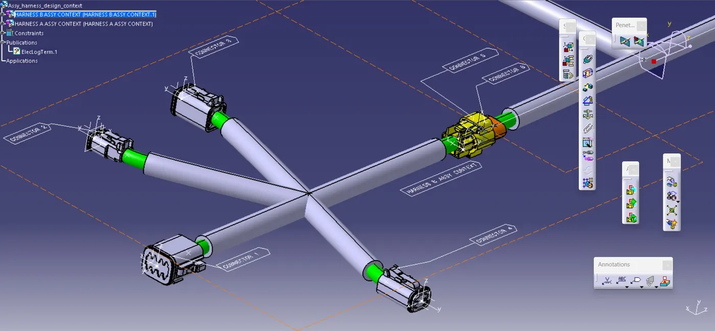
Create and connect multiple branching point:
- In this challenge as usual we are going to define and position the connectors and create the branches.But here we are going to work with multiple geometrical bundle assembly in one harness design assembly context.
- For that we need to create two induvidual geometrical bundles names that Harness B Assembly context and Harness A Assembly context.
Harness B Assembly context creation:
- First we need to downlode connectors from the te.com.then we need to define and position it on Harness B Assembly context Product file.
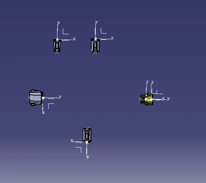
- Here we need to rotate the connector 1 by using compass.because the starting bundle connection point interchanged.
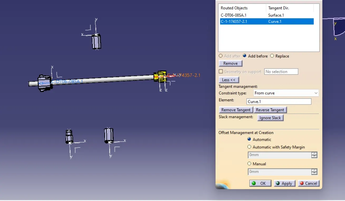
- After changing that we are going to create the multiple branching document.During the branching I saw the tangengy error between connector 2 and main branch,by reversing the direction of tangency management I was easily rectify that.as below mentioned snap.
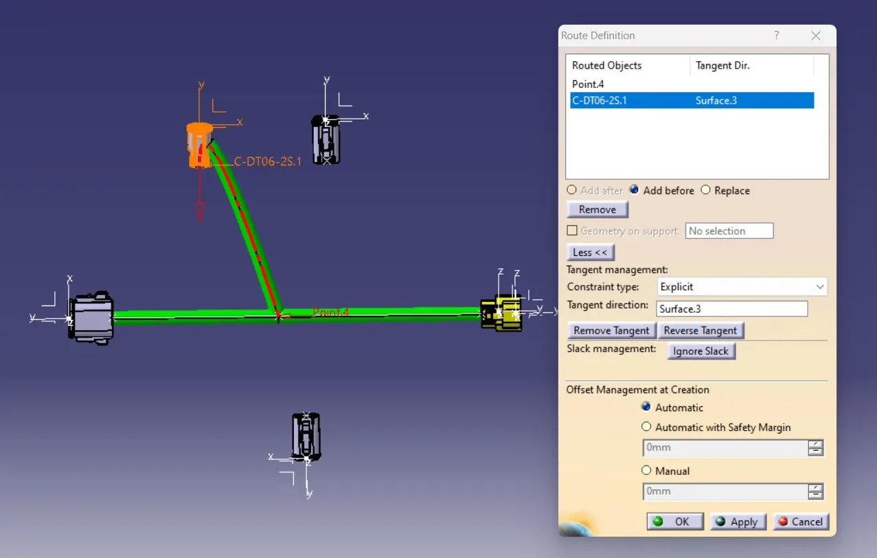
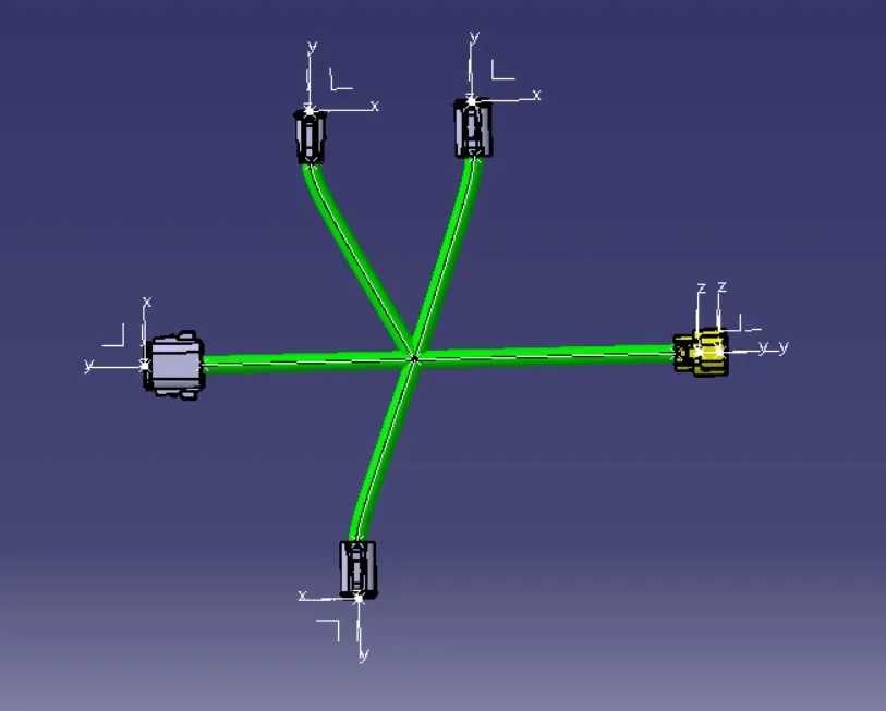
- After creating the branching we got the final out of Harness B assy context.
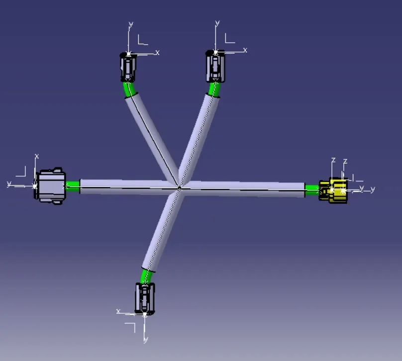
- Now we need to add protective covers and add extrimity to the corrugative tubes.
Craetion of Harness A assembly context:
- First we need to downlode connectors from the te.com.then we need to define and position it on Harness A Assembly context Product file.
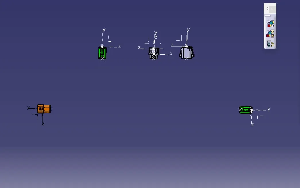
- As per given layout we are creating the main branch,and this time we are create the branching for connector 7 using the external curve method.
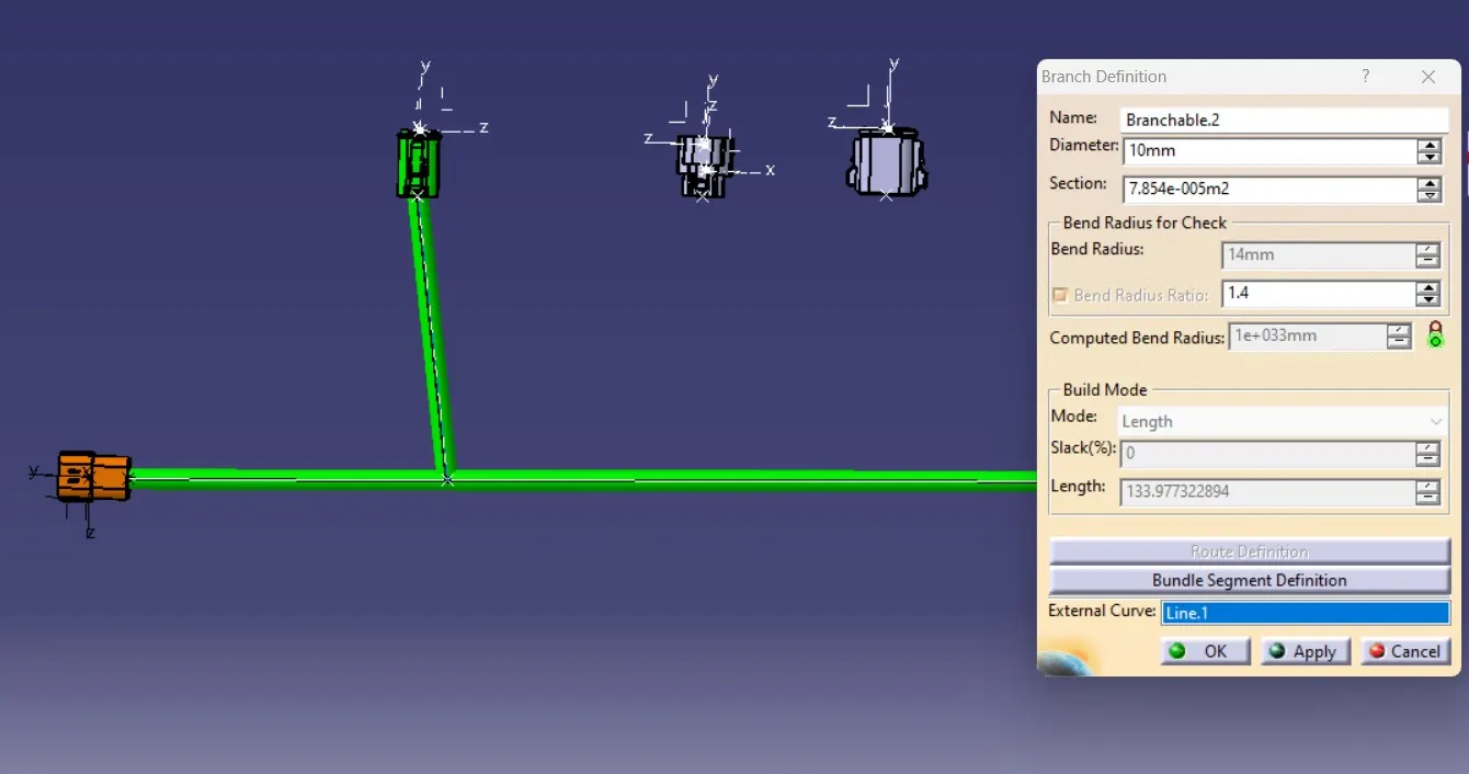
- During Braching to the conector 8 and connector 9 I was face the error.as below mentioned.If you face any error on dururing routing you will notice the exlametry symbol on feature tree.
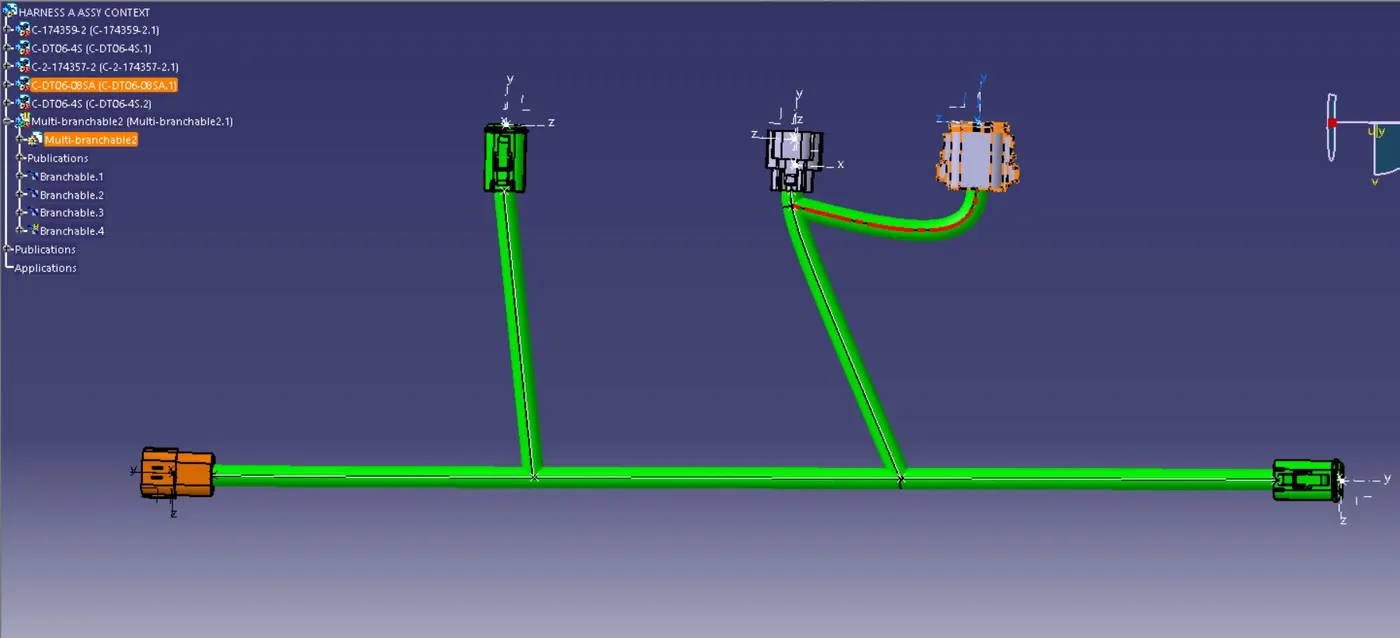
- By Adding slack to 10 percentage ,the computed bending radius incresed above to nominal bending radius and the problem was solved.
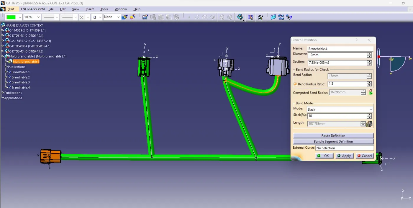
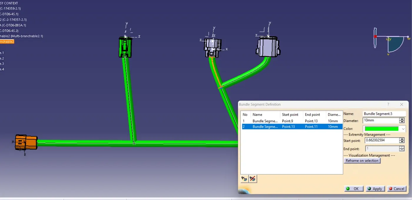
- But this method is not aesthetically good so i choose to adjust the branching point.For that we go for bundle segment definition in Branch definition and edit the extrimity Management.In this edit we can edit the color,diameter of the bundle easily.
- we are change the start extrimity to 0.6 we get asthetically good branching and solving the tangency issue.now we need to change the slack percentage to 0.
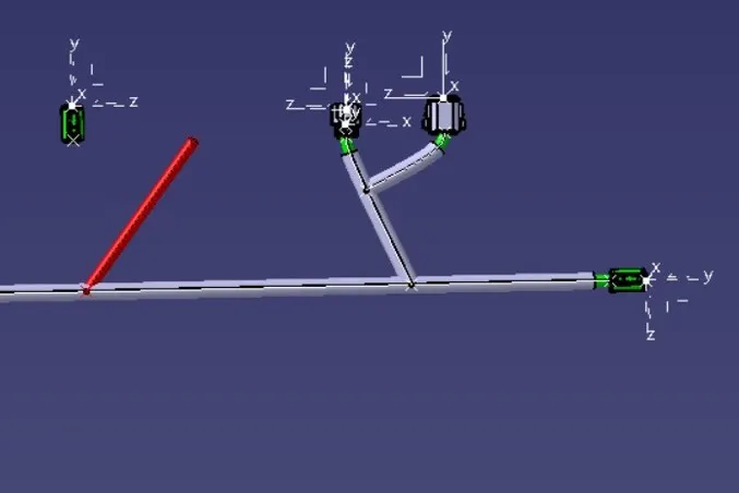
- After branching we need to move the connector means we saw the bundle color changed to red by using update icon we resolve this error.
Connection of Harness A and B:
- Create a new product file as a Assembly harness design context and copy and paste the Harness A and B assembly.
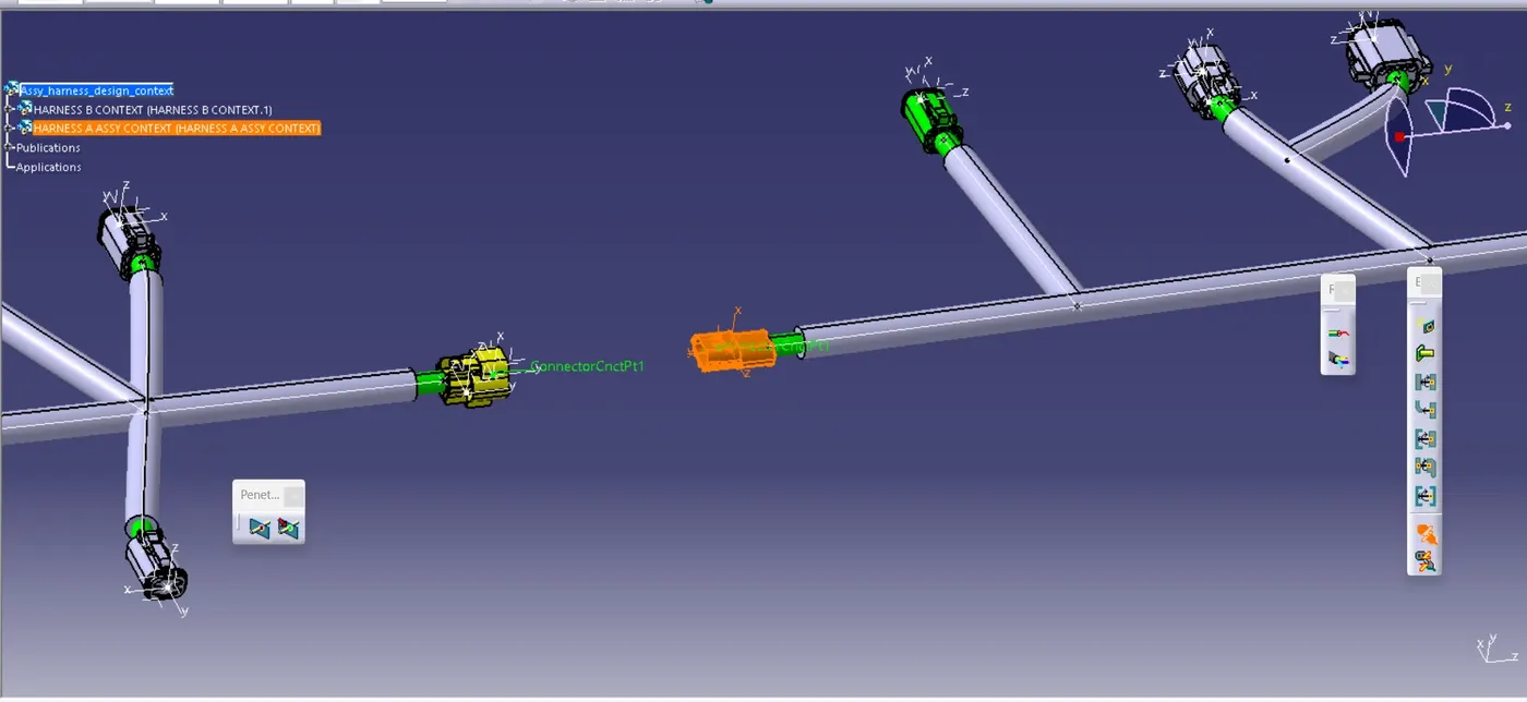
- Then Using electrical design assembly interface and connect the connector using electrical connector icon.
- after that we are got our final out as below mentioned diagram.
Bundle continuty check:
- By this option we are find out the continuty between the bundle segment and branches inside the routing.
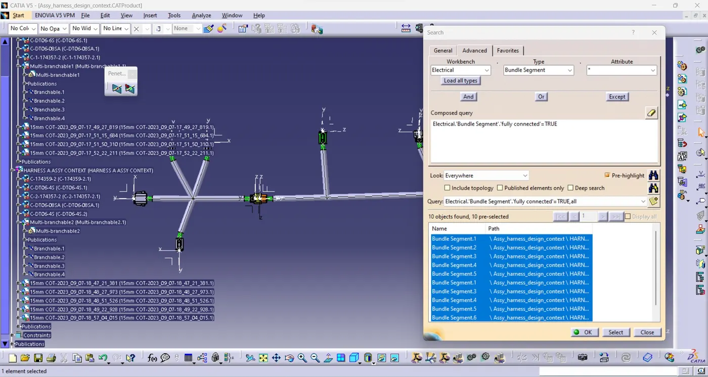
- For that we need to go edit--->search,you got the wizard like below mentioned we need to select the workbench as electrical,Type as bundle segment and give fully connected and true or false to the atribute.
- In true logical sequence it shows the fully connected bundle braches names.
IF TRUE:
IF FALSE:
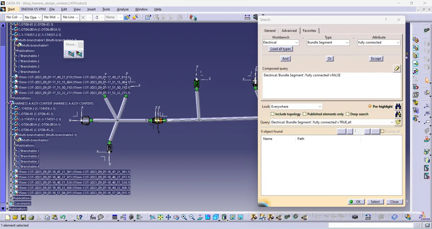
- From above mentioned pictures we findout our routing design ws fully connected.
Annotation to the connectors:
- Annotation is used for identify the elctrical components and give the additional information about the connectors,channel and etc....
- For that first we need to go mechanical assembly design work bench.Then you can find out the like below mentioned tools.
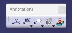
- Above mentioned tools we can create label and without label annotations.
- for that we need to create reference plane using the view of reference icon.
- Then create the annotation as below mentioned pictures.
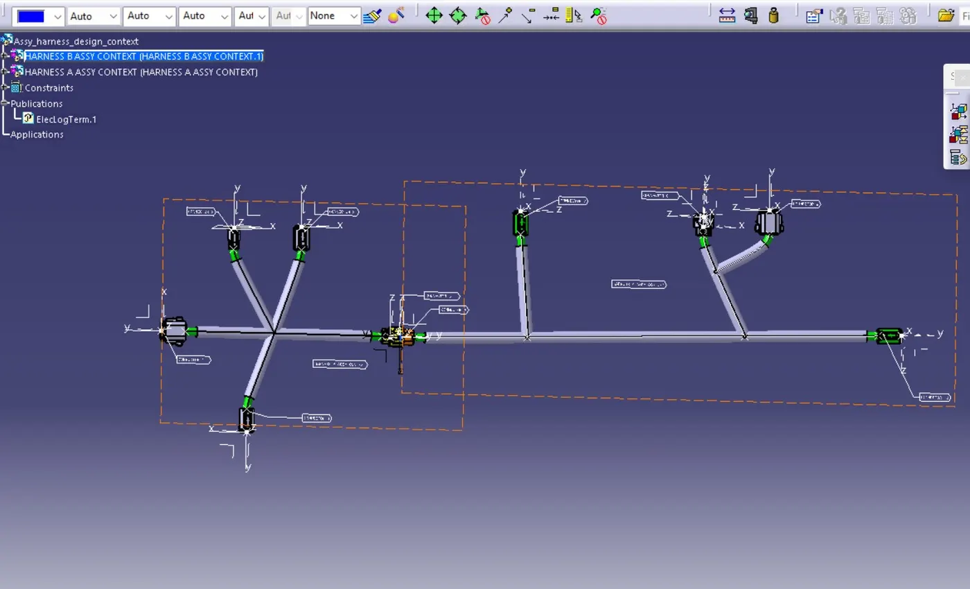
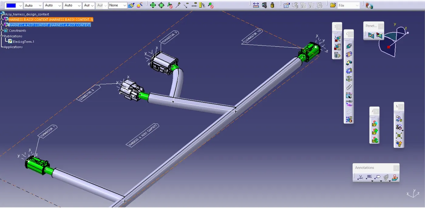
Bundle warning check:
- We are fully checked there is no bundle warning.
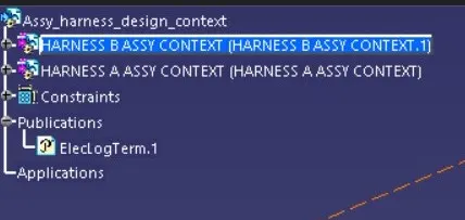
.CAT part & .igs file creation:
- After those steps we need to check the save management.
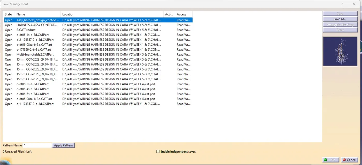
- all parts are successfully saved.
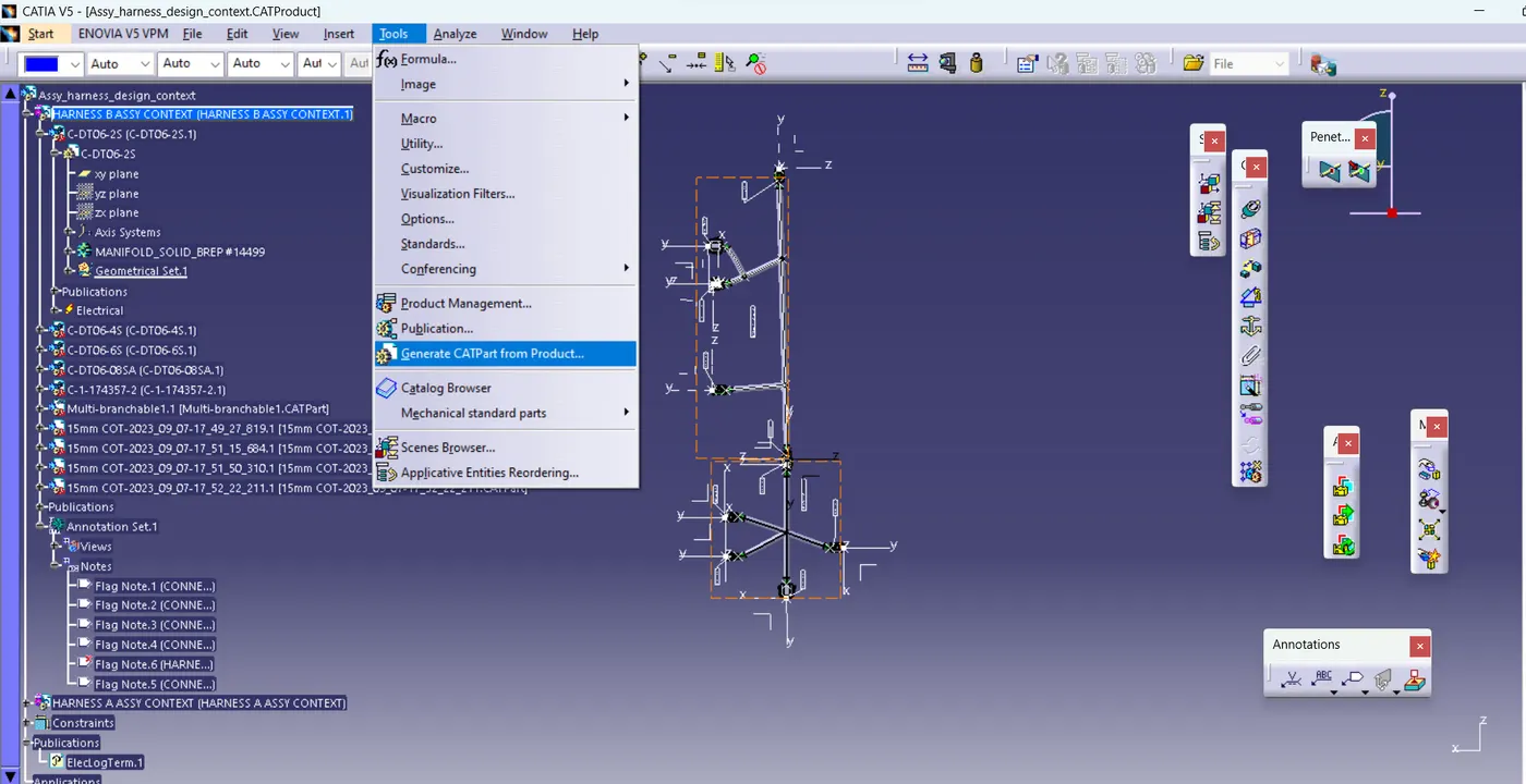
- Then go to Tools--->Generate.CAT part from product.... we are easily create the .CAT Part from the product file then we saveas that as a igs file.
Conclusion:
- From this challenge we are learned how to create and connect multiple branching points,tangency management,routing with external curves,bundle continuty check/analysis,geometrical bundle warnings and 3D annotations Successfully.