Wiring harness design in CATIA V5 - 3D modeling Week 5 & 6 Challenge
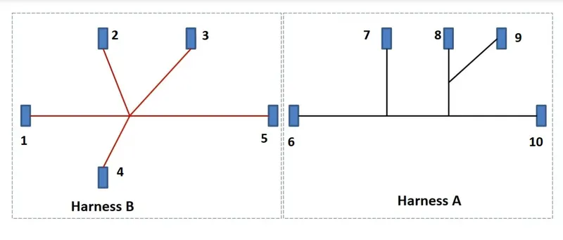
AIM: Q1. Route the following harness layout in Electrical workbench. Make assumption for harness bundle diameters. Use the connectors provided.
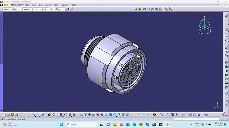
Electrical connector: An electrical connector is a device or mechanism used to establish a physical and electrical connection between two or more electrical circuits or components. Connectors enable the transfer of electrical signals, power, or data between different devices or systems. They come in various shapes, sizes, and configurations to accommodate different requirements, such as the number of pins or terminals, the type of signal being transferred (analog or digital), the environment in which they will be used (indoor, outdoor, harsh conditions), and more.
Electrical connectors typically consist of two main parts:
- Plug: This is the male component of the connector, usually having protruding pins, prongs, or sockets that match with corresponding receptacles in the female component.
- Receptacle: This is the female component of the connector, designed to accept the plug and create a secure electrical connection with its pins, prongs, or sockets.
Wire: Wires are essential components of wire harnesses, which are organized assemblies of multiple wires, cables, or conductors that are bound together in a specific arrangement and encased in a protective covering. Wire harnesses are used to transmit electrical signals or power between various components, devices, or systems within a larger structure, such as an automobile, aircraft, industrial machinery, or electronic equipment.
Protective Covering: The protective covering in a wire harness serves as a barrier that shields the individual wires and cables within the harness from various environmental factors and mechanical stresses. This covering not only provides physical protection but also contributes to the overall organization, durability, and reliability of the wire harness. There are different types of protective coverings used in wire harnesses, each designed to address specific requirements and conditions.
Ex: Heat Shrink Tubing, Conduit, Tape, Loom, Cable Tie, Spiral Wrap, Connector Boots, Grommets, Heat-resistant Sleeving.
Below Steps need to be followed to create the Wire Harness
1. Download Connector 3D:
- Download CAD data from manufacturers' or distributors' official websites.
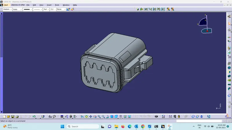
Harness A - Connectors
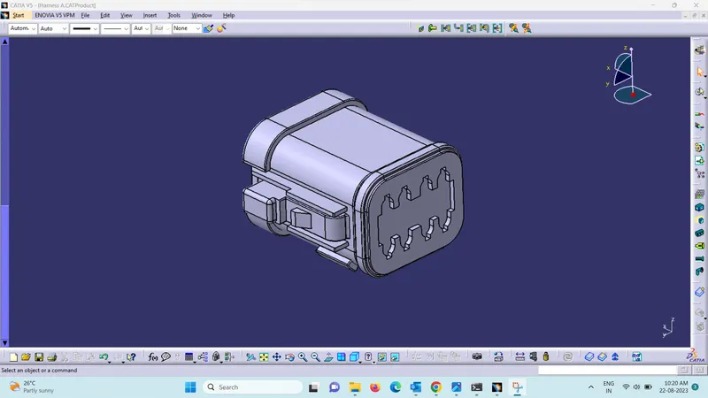
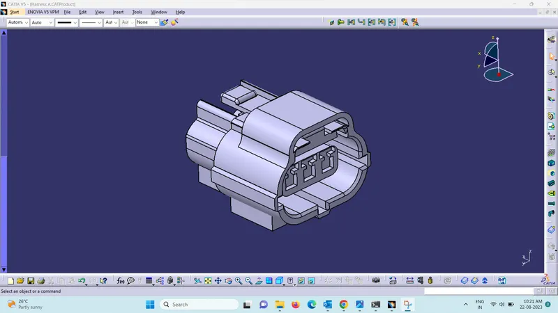
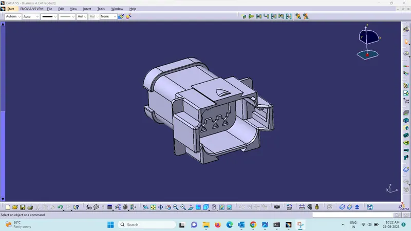
Harness B - Connectors
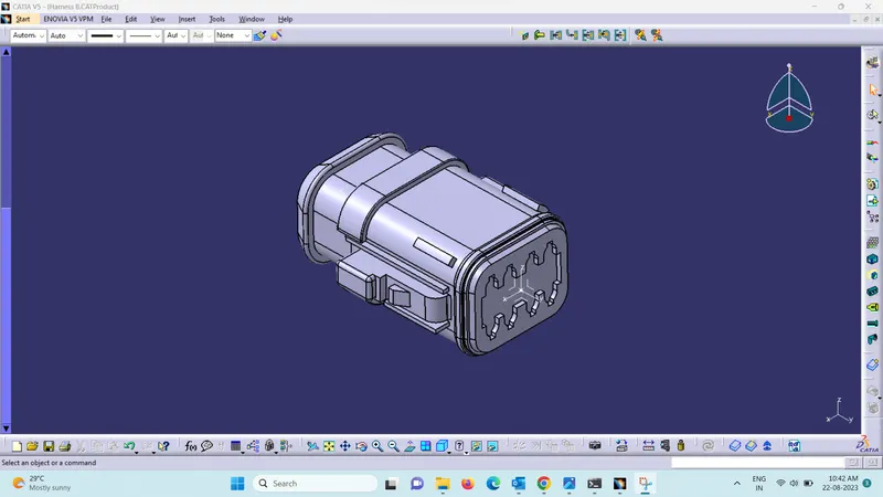
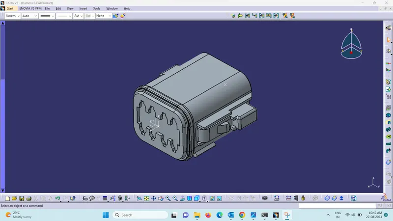
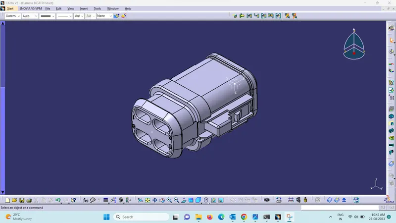
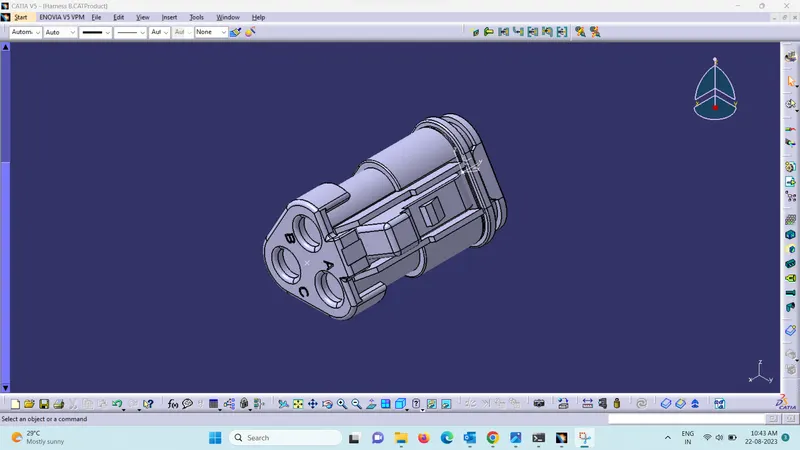
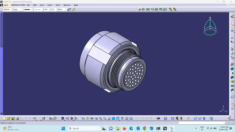
Create Required Geometrical Parameters:
- Create Connector Connection Point using the Part Workbench for Connectors.
- Create the axis using point as reference using the Part Workbench.
- Create Bundle Connection Point using the Part Workbench.
2. Create Assembly file:
- Create the Assembly file and import all the connectors and position them as shown in the figure or requirement.
- Go to Electrical Harness Assembly workbench and use “Geometrical Bundle” option to convert the Part Assembly file to Electrical Part Assembly file or bundle.
- Use “Multi-Blanchable Document” and “Add Local Slack” option to create the branch between connectors.
- Use “Protective Covering” option and add the necessary protective covering using the catalog, where coverings are created and stored.
Harness A - Assembly
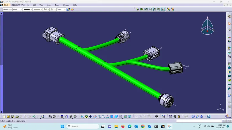
Harness B - Assembly
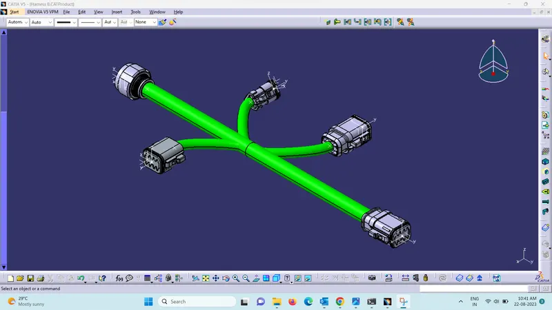
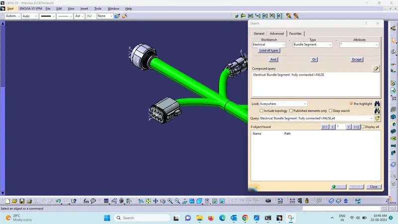
Harness A - Bundle Connectivity
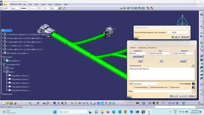
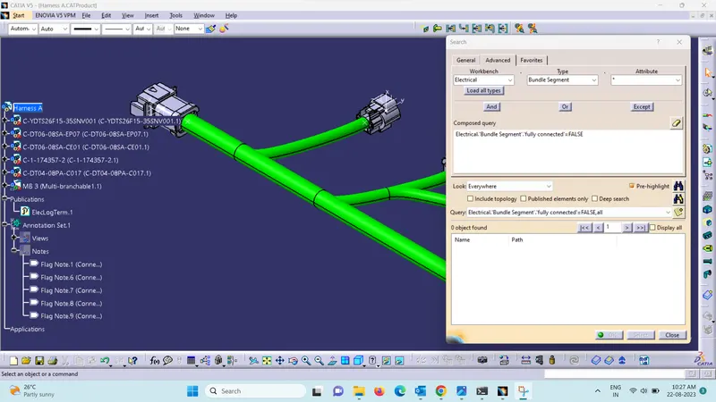
Harness A - Bundle Connectivity
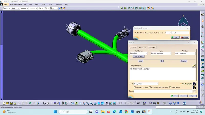
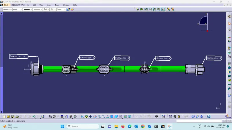
Harness A - Annotation Creation
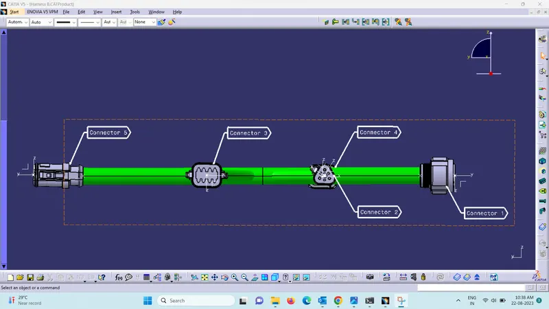
Harness B - Annotation Creation
Interconnection for Harness A and B
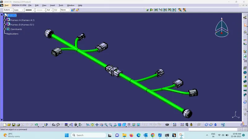
Harness A and B - Bundle Connectivity
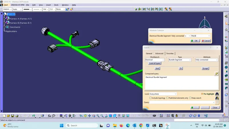
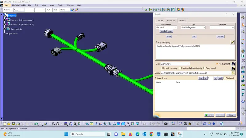
Conclusion: Hence the Harness A and B are created and a interconnection is made between the Harness A and B. Connectivity is checked individually for Harness A and B and also to the Assembly of Harness A and B.