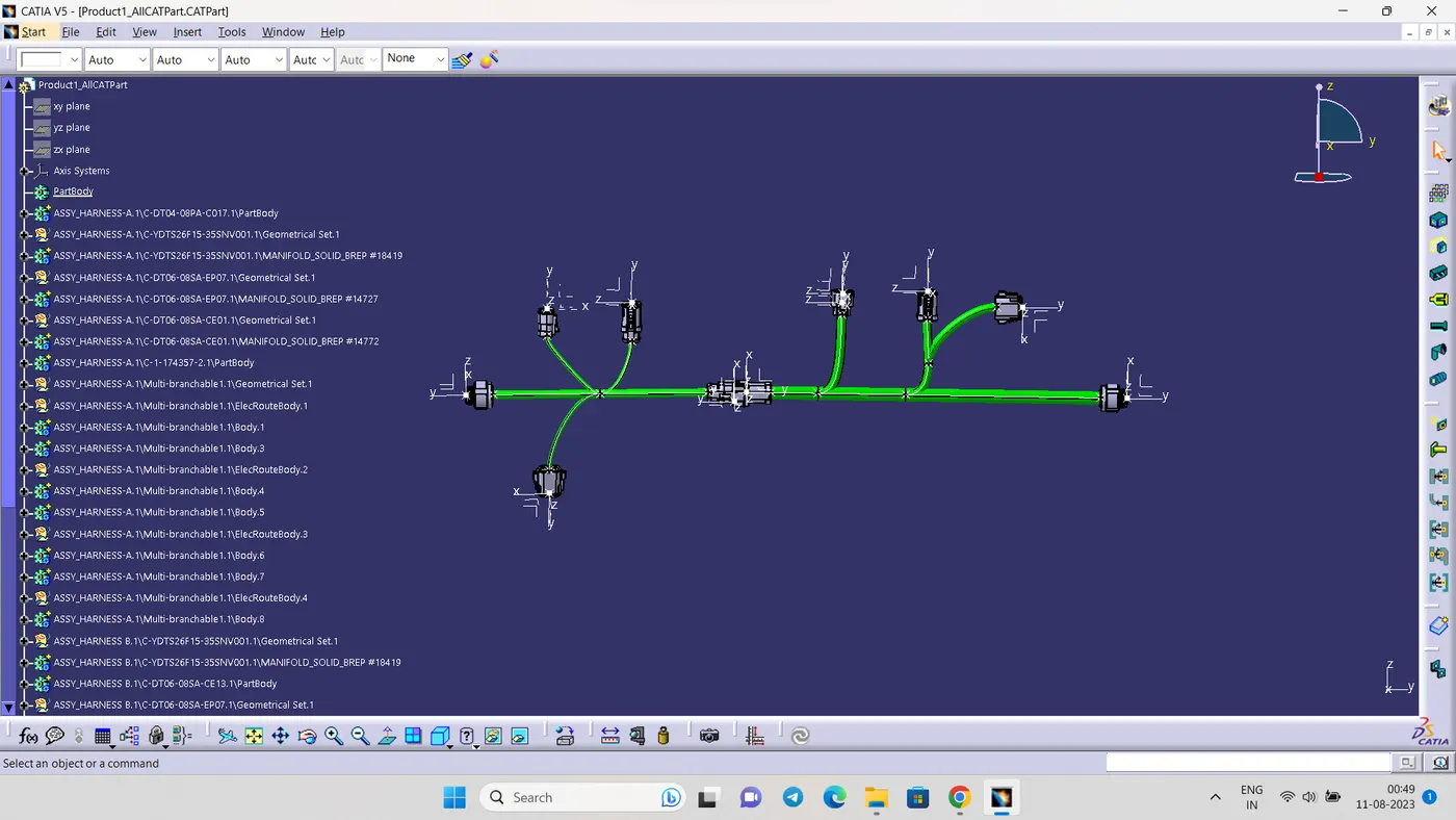
Wiring harness design in CATIA V5 - 3D modeling Week 5 & 6 Challenge
QUESTION:
Route the following harness layout in Electrical workbench. Make assumption for harness bundle diameters. Use the connectors provided. After completion of routing,
- Check the bundle Continuity. Add snap of result in submission
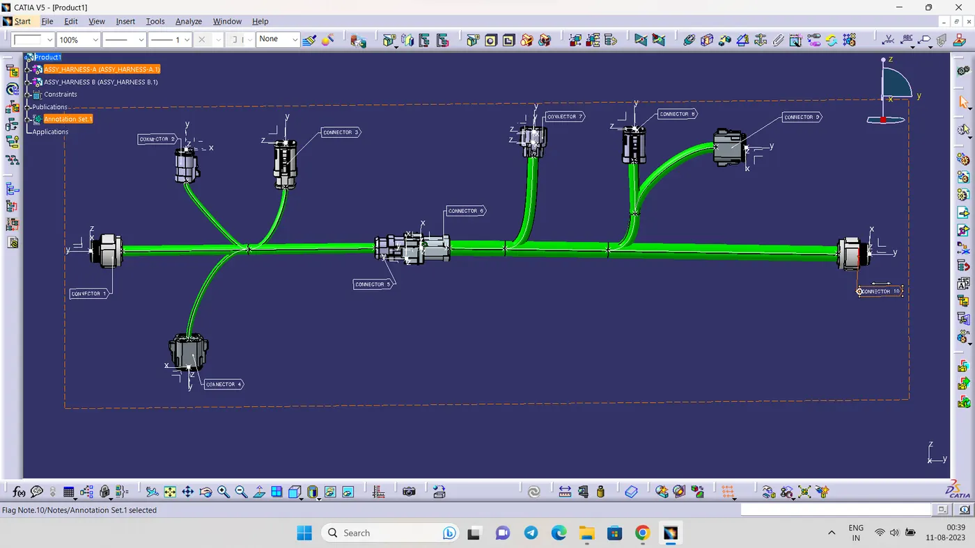
- Add annotation to all connectors. Make an assumptions for annotations like connect 1 , 2 etc
- Check for the bundle warning. Add snap.
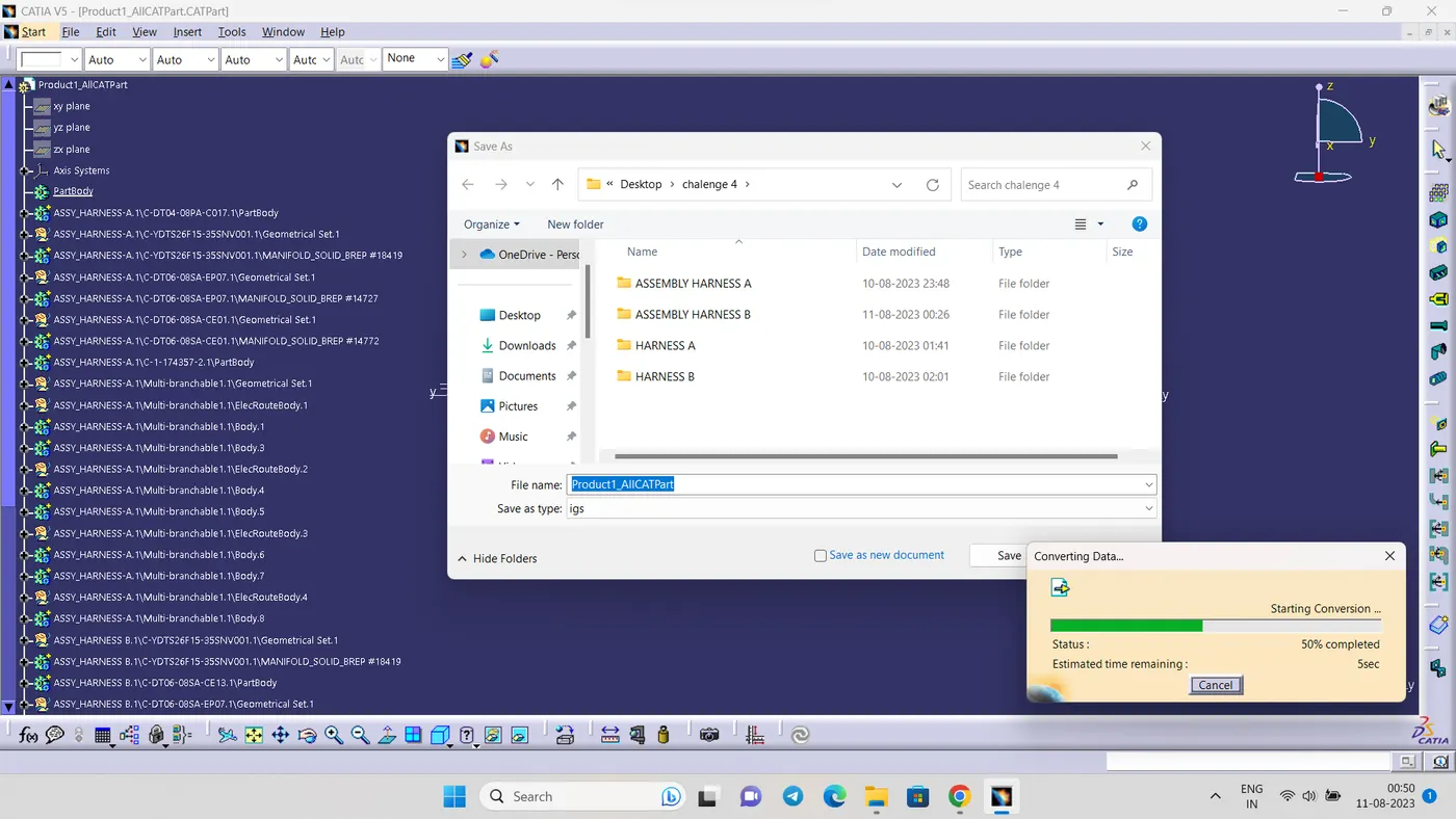
- Generate CAT.part of harness assembly and convert is in. igs format.
SOLUTION:
- STEP 1
Create an catalog with 2 family harness a connectors and harness b connector
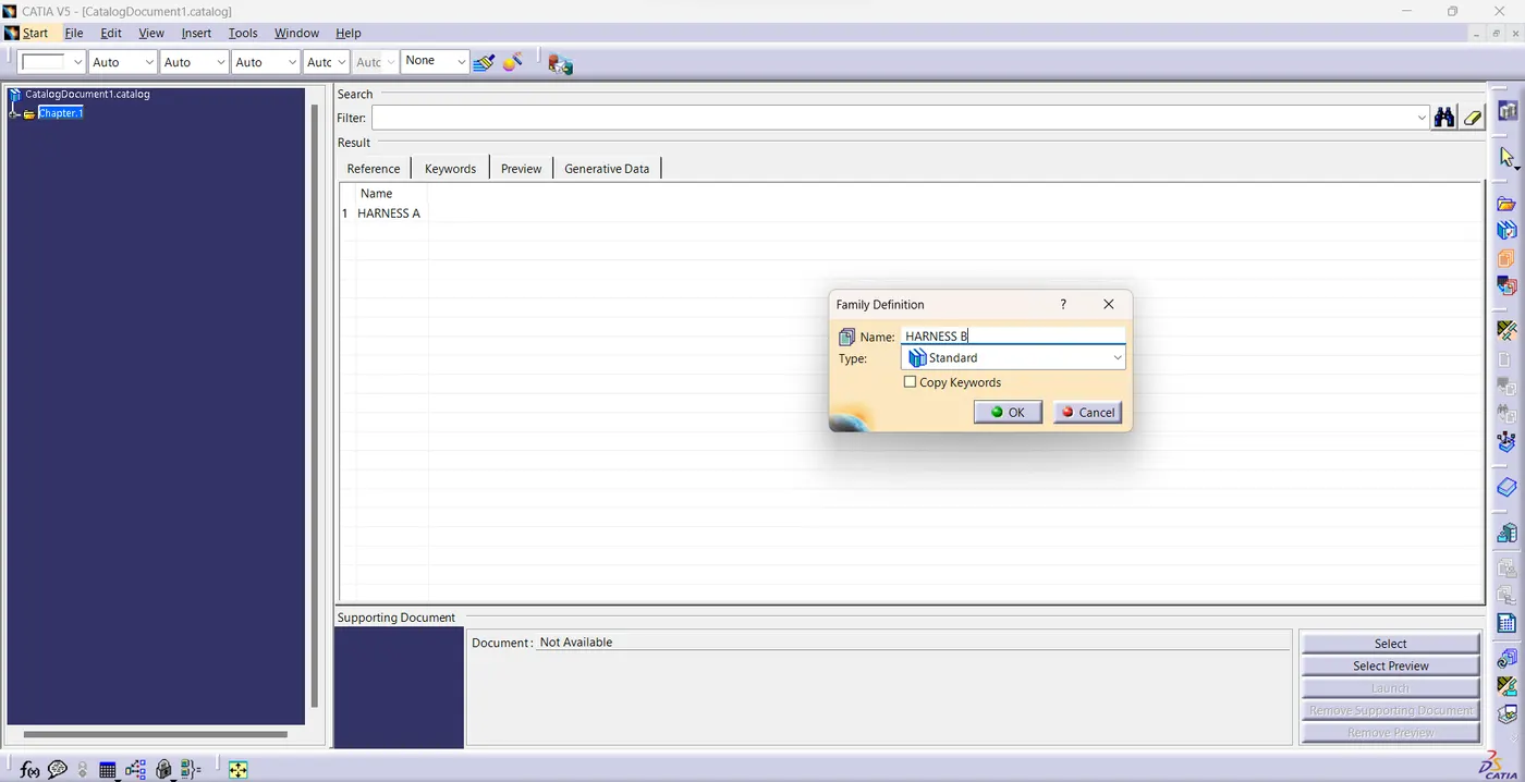
- STEP 2
Define all the components to electrical components and define connector connection point and buntle connection point
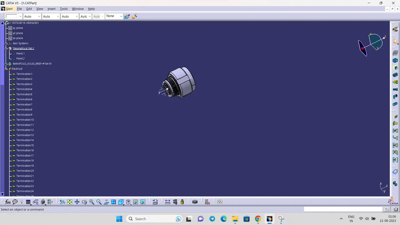
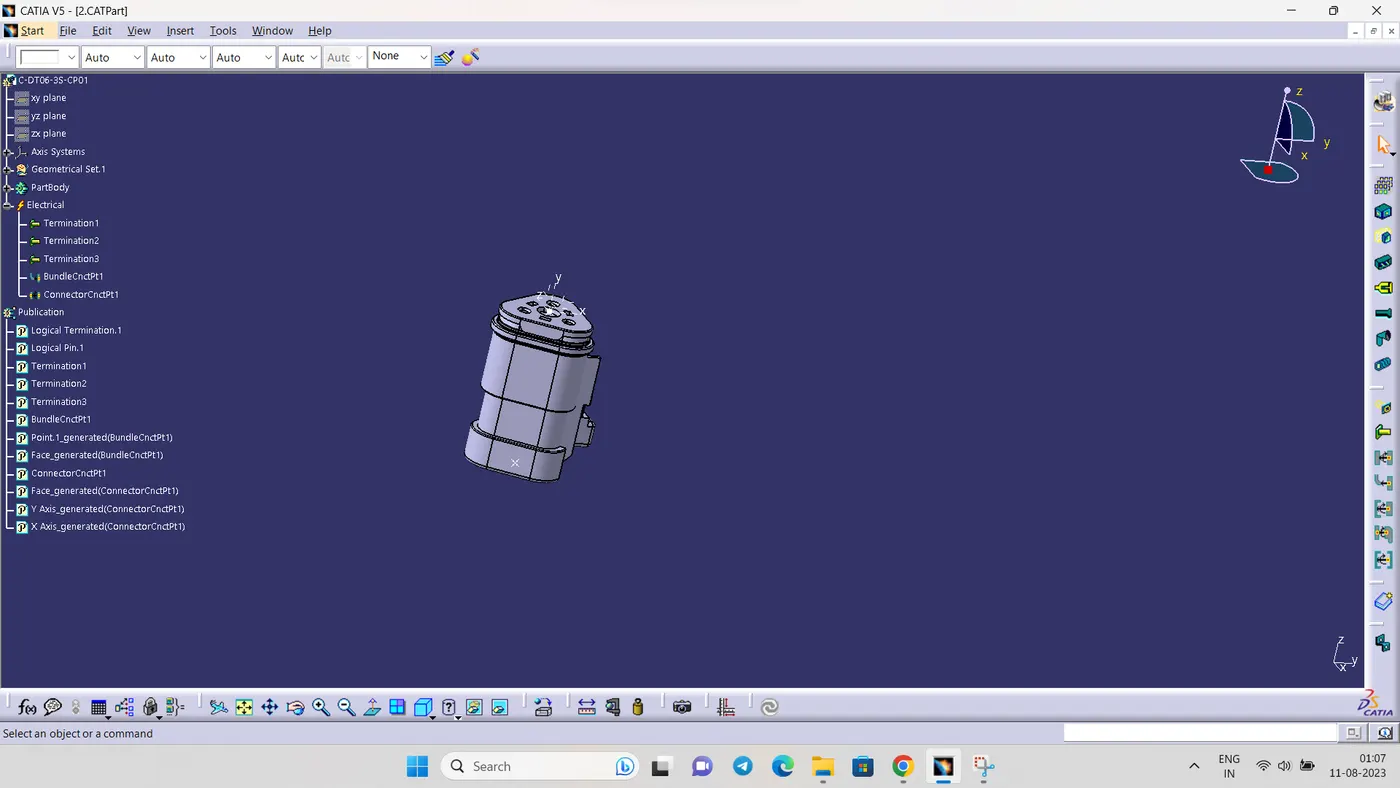
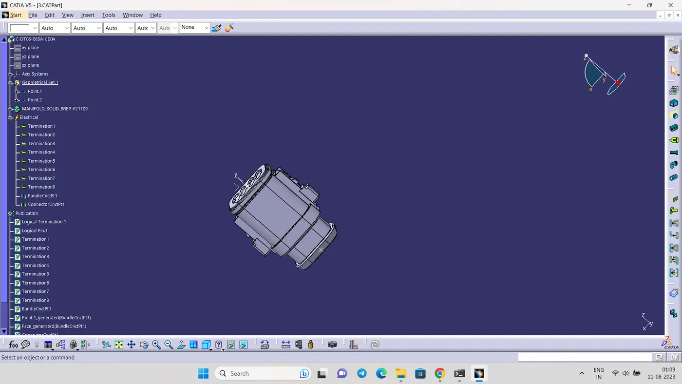
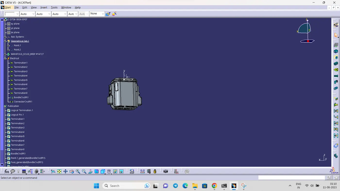
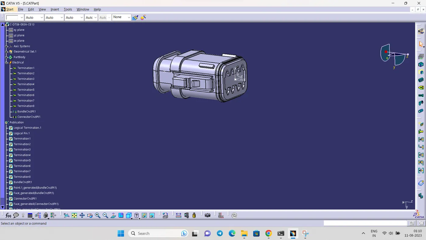
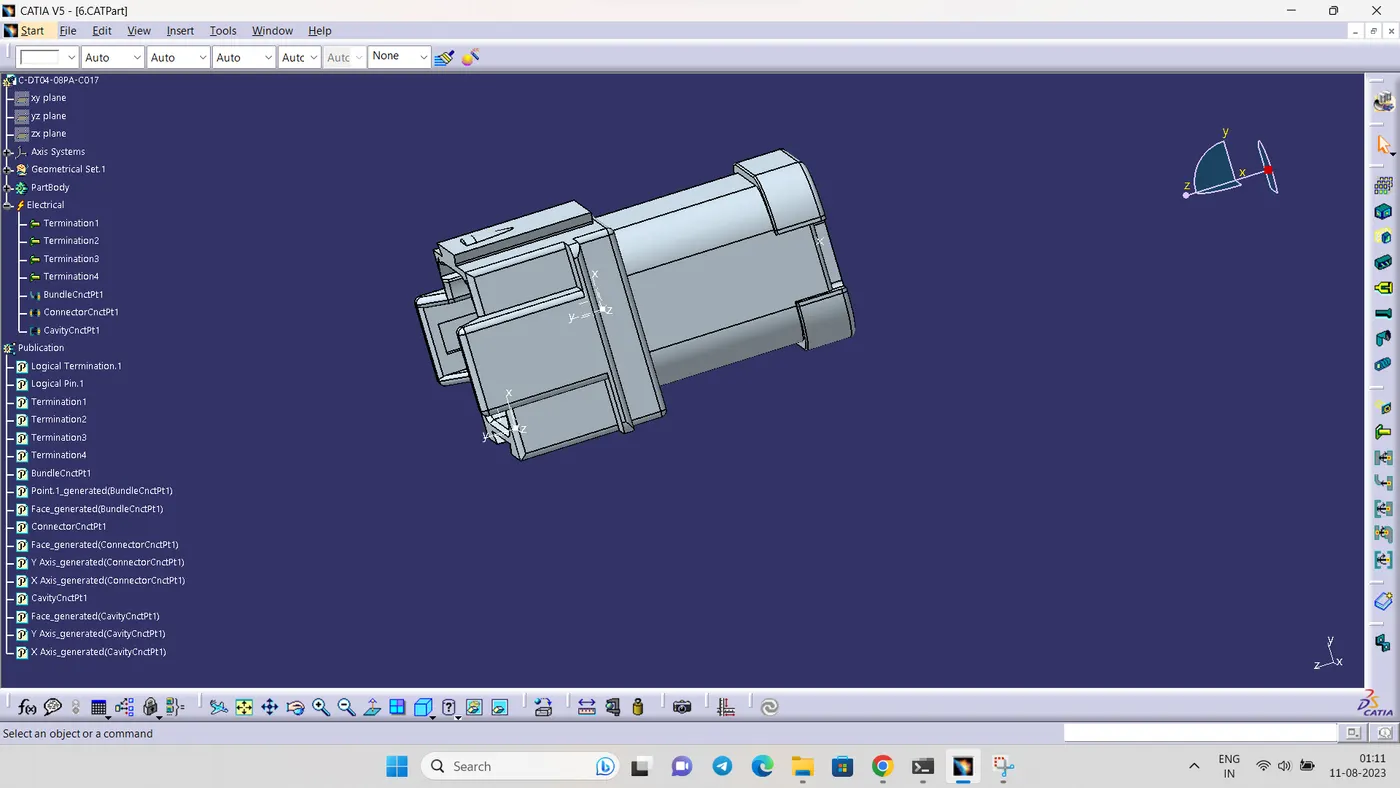
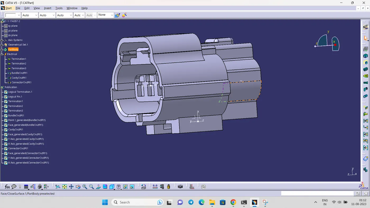
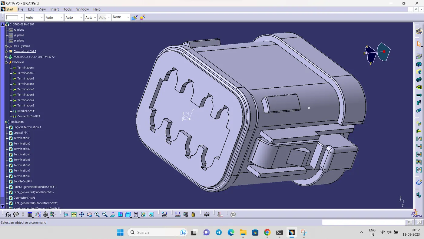
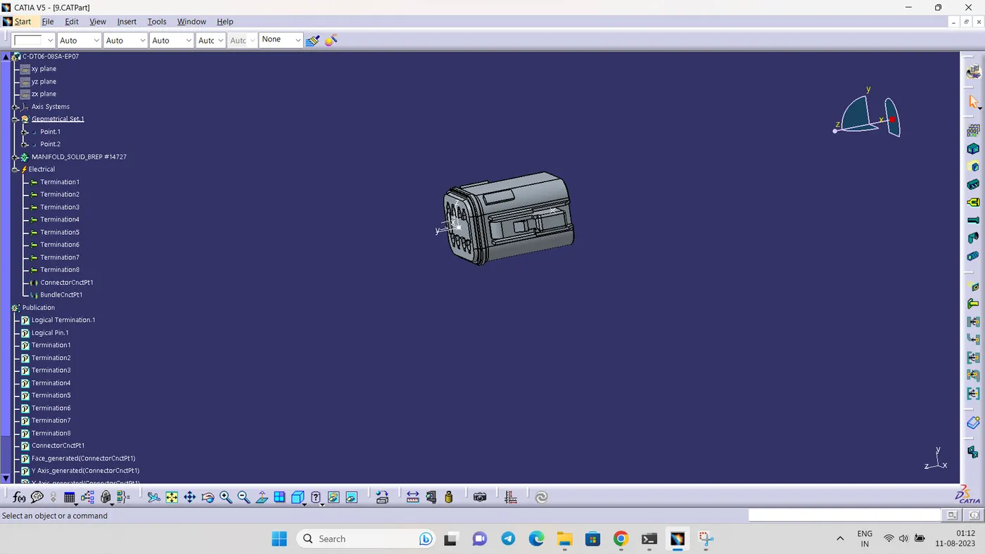
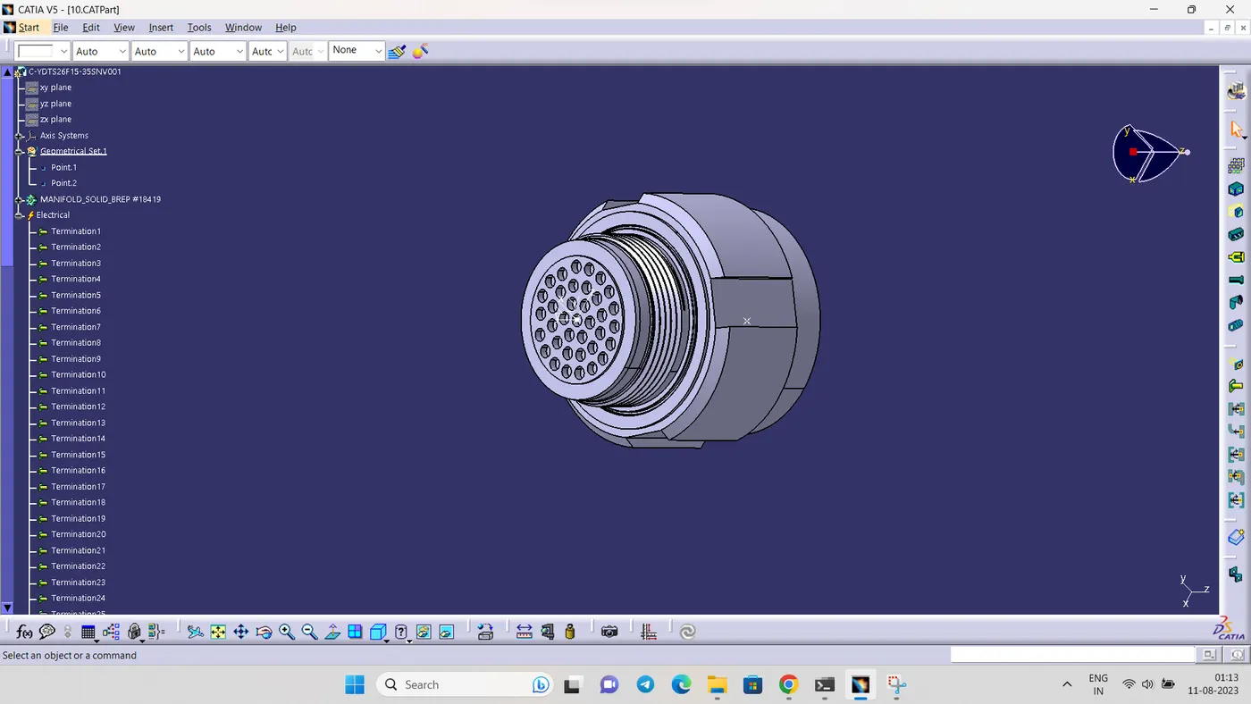
- STEP 3
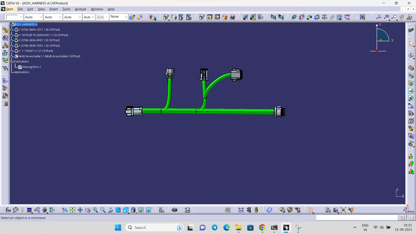
HARNESS A CREATION
After all the connectors are defined, the workbench was switched to Electrical Harness Assembly where Geometrical Bundle was activated. All the connectors were routed using the Multi-Branchable Document command.
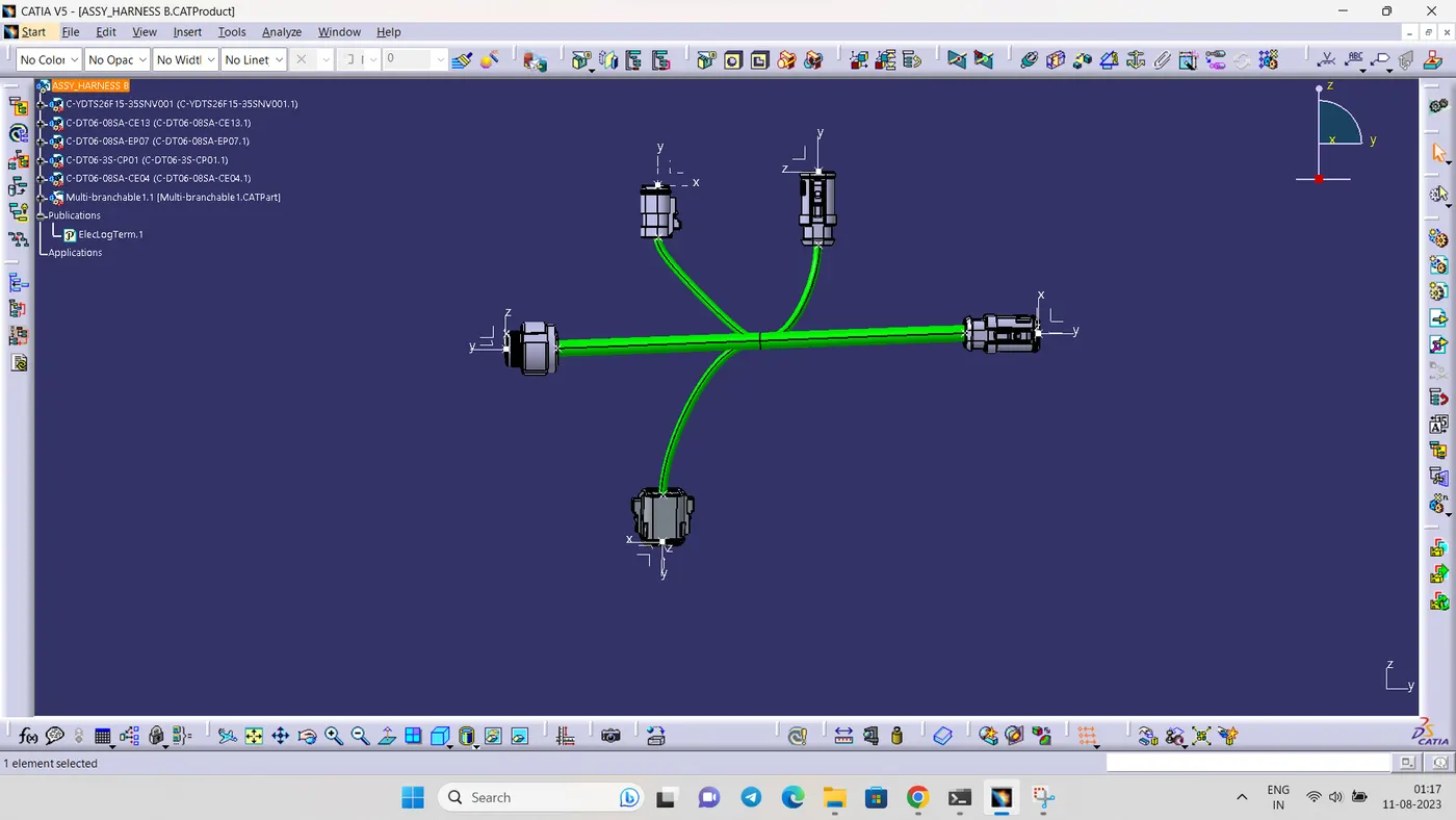
HARNESS B CREATION
After all the connectors are defined, the workbench was switched to Electrical Harness Assembly where Geometrical Bundle was activated. All the connectors were routed using the Multi-Branchable Document command
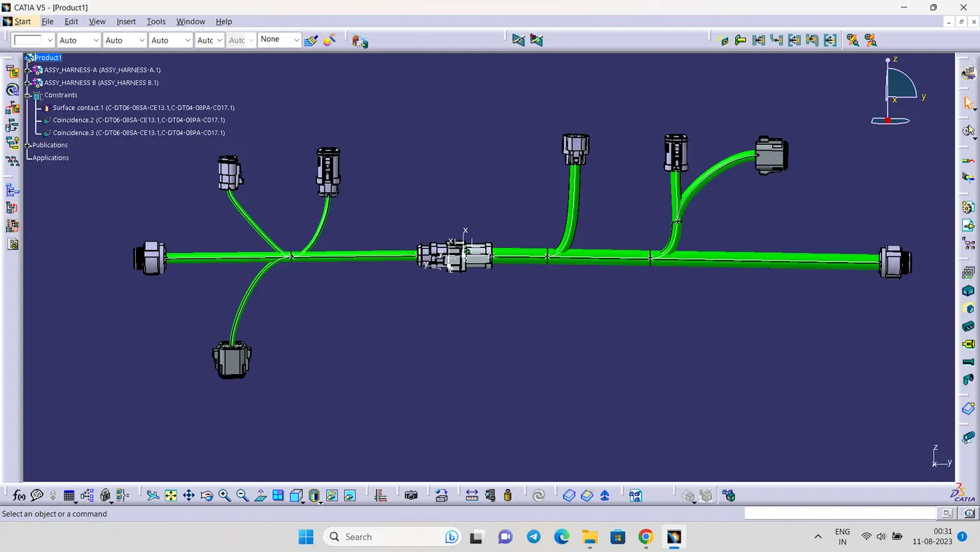
HARNESS ASSEMBLY
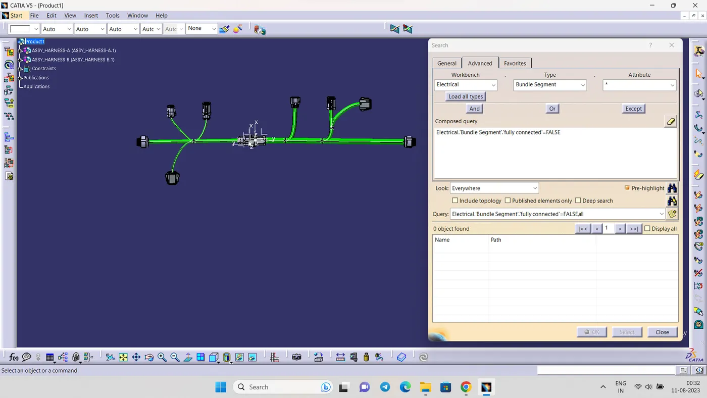
After create the harness A and harness B product assemble the togother
- STEP 4
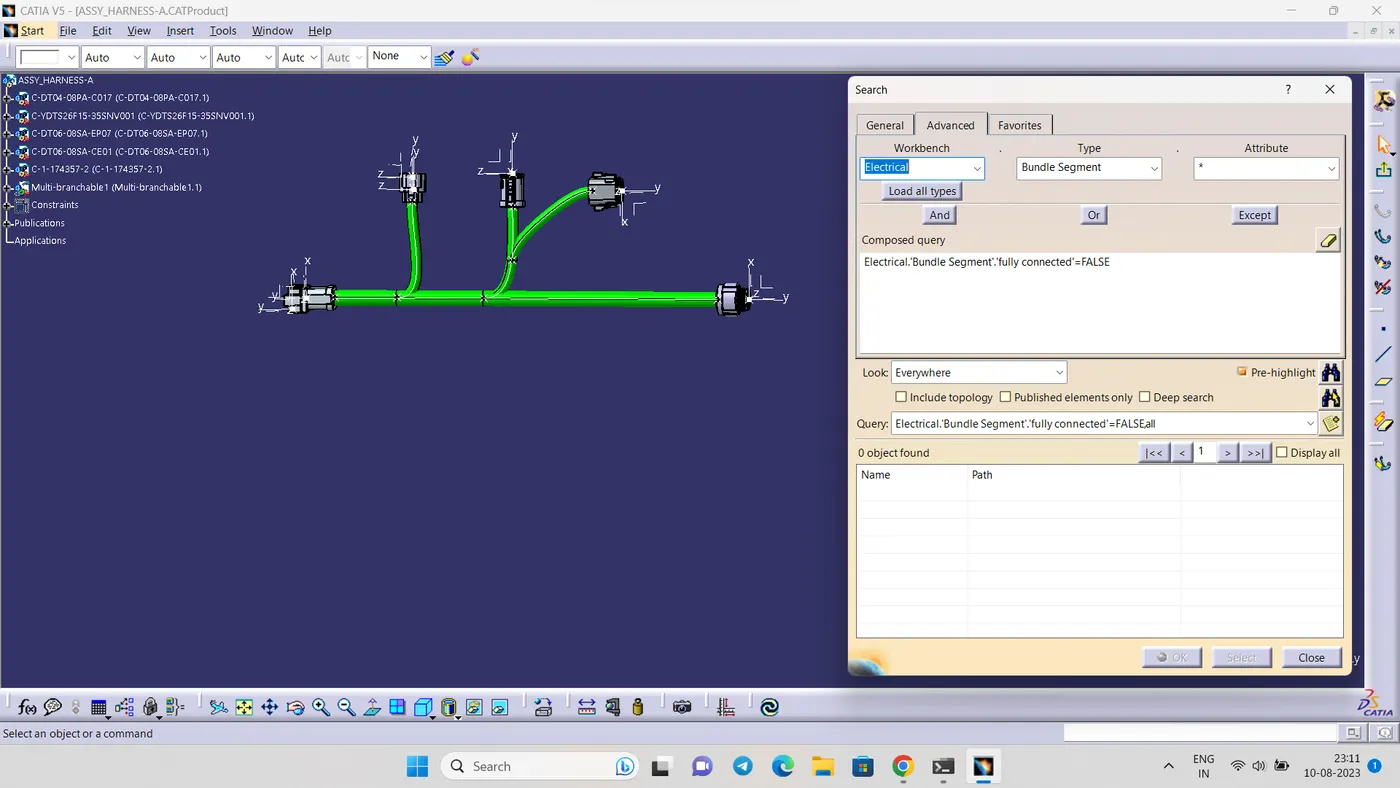
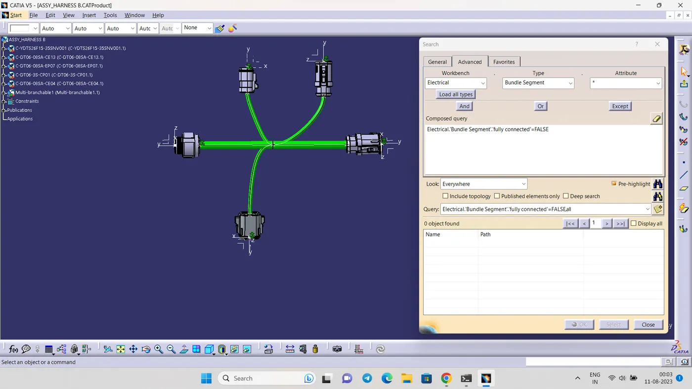
Check the connectivity of the bundle
- STEP 5
Add annotation to all connector
- STEP 6
Convert the product file into cat part file and save it in igs format