Wiring harness design in CATIA V5 - 3D modeling Week 5 & 6 Challenge
ASSEMBLE FOR HARNESS B AND HARNASS A :
CREAT MECHANICAL CONNECTOR ELECTRICALY STORE IN CATALOGUE:
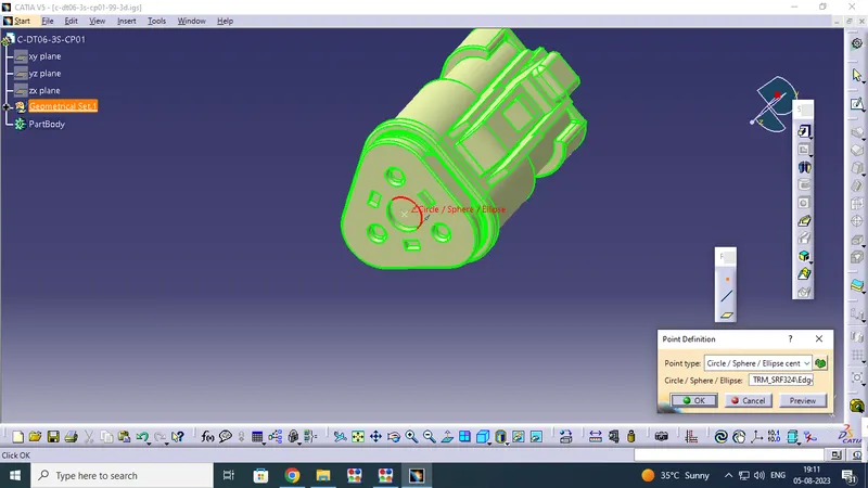
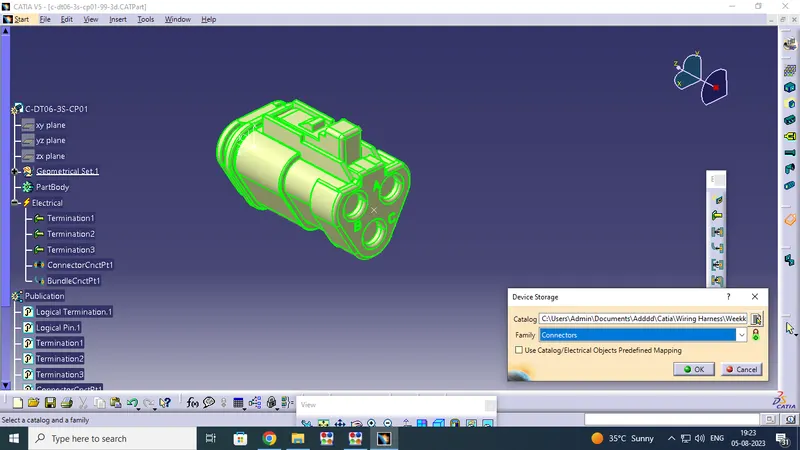
Download the connector in TE.COM then cad file open on electrical part design work bench to get modified on identify the what is connector connectivity point and bundle connectivity point. then create define Connector , Connecter connectivity point and buldel connectivity point with the help of point and axis tools. After complete the process then go to pick store device option and save the connector catalogue files.
PREPARATION FOR MECHANICAL CONNECTORS TO ELECTRICALLY :
We have select Below type of connectors in this Challange ,they are .,
1. c-ydts26f15-35snv001-99-3d
2.c-dt06-3s-cp01-99-3d
3.c-dt06-08sa-ce04-99-3d
4.c-dt06-08sa-ep07-99-3d
5.c-dt06-08sa-ce13-99-3d
6.c-dt04-08pa-c017-99-3d
7.c-1-174357-2-e-3d
8.c-dt06-08sa-ce01-99-3d
9.c-dt06-08sa-ep07-99-3d
10.c-ydts26f15-35snv001-99-3d
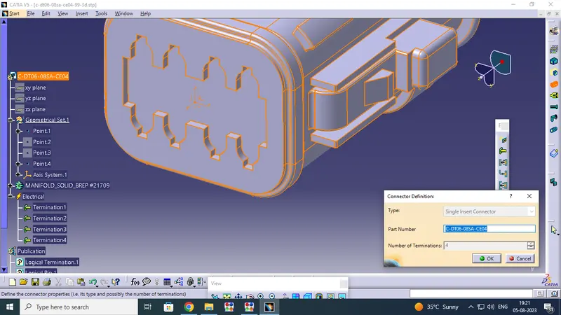
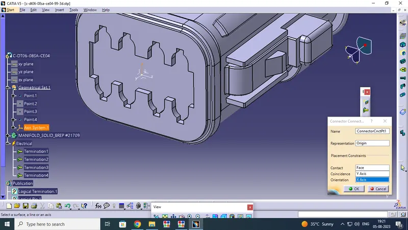
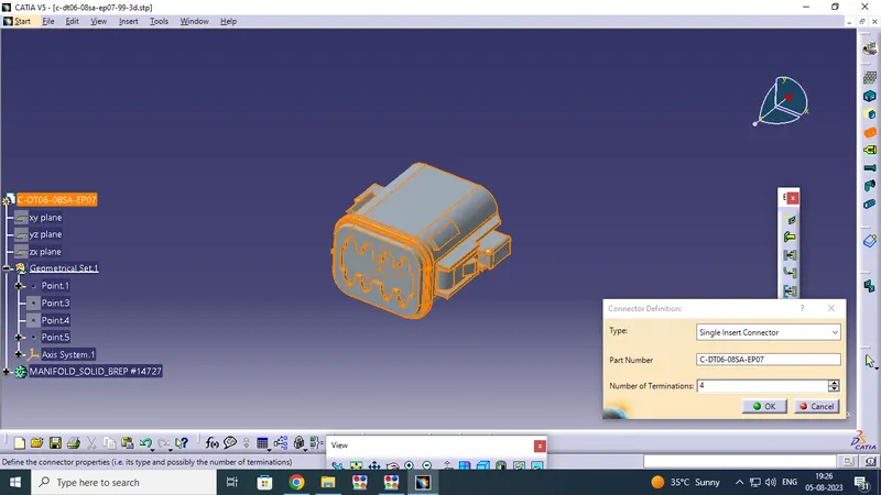
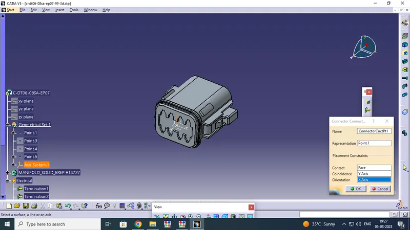
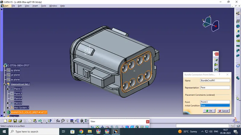
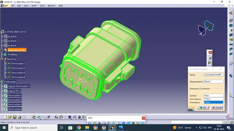
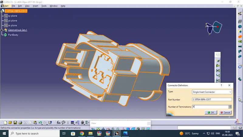
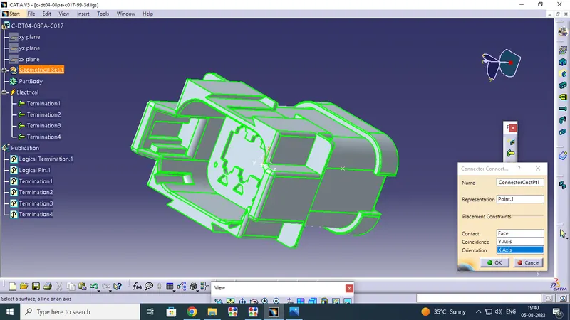
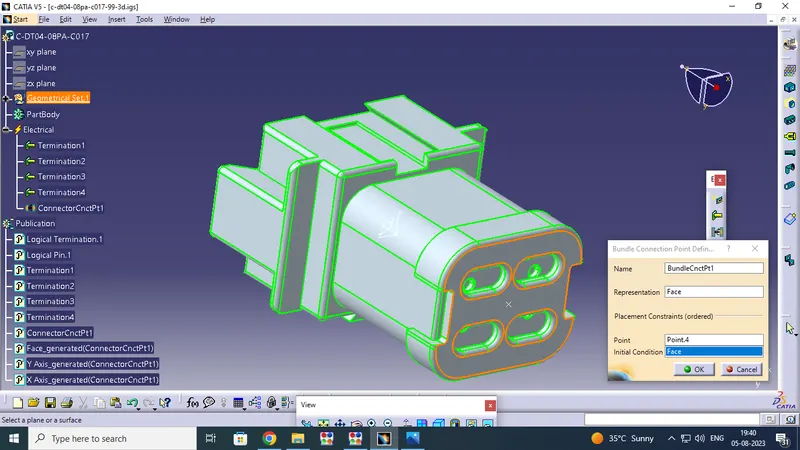
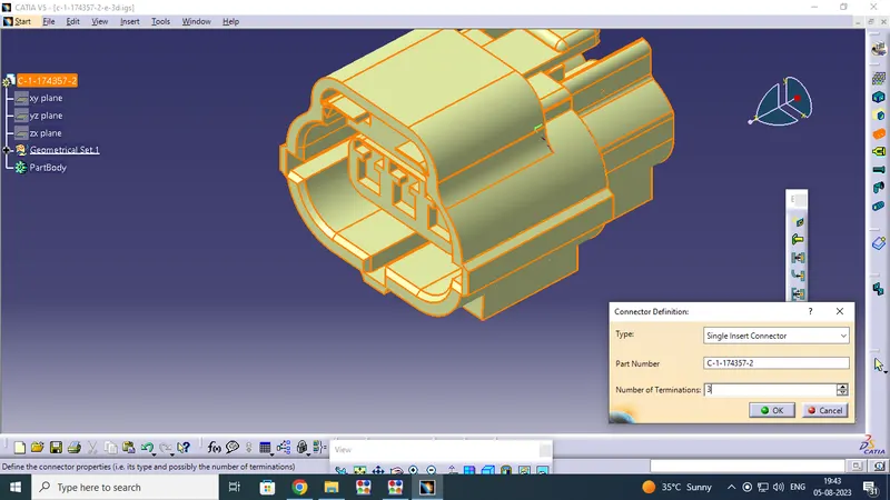
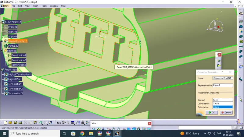
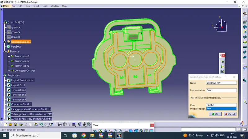
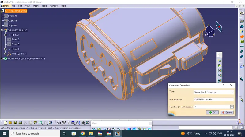
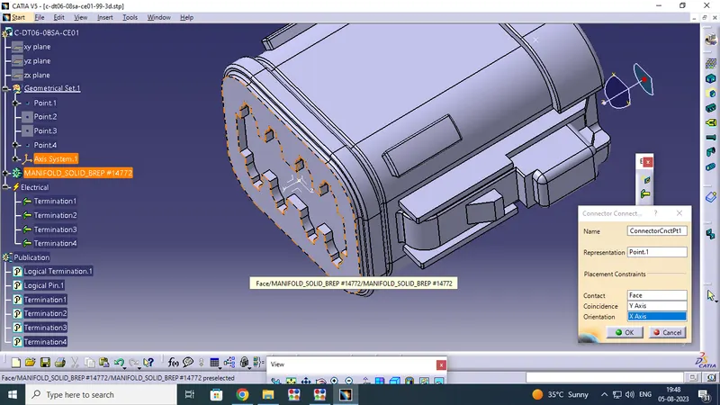
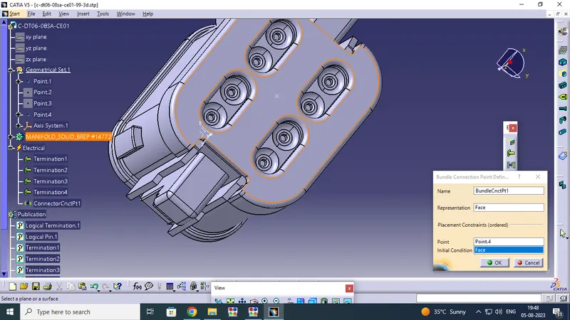
Download the connectors from TE.COM.Open the website enter Connectors Model Number in Search Button, and open the connectors Select and download the CAD Zip file.Finally open the cad file by using CATIA Sostware Identify the connecter connectivity and bundle connectivity in Part workbench.Then we have been creat the point and axis in mounting direction by using part work bench.like y axis direction is coinsidence ,x axis is orientation and z axis is side facing.
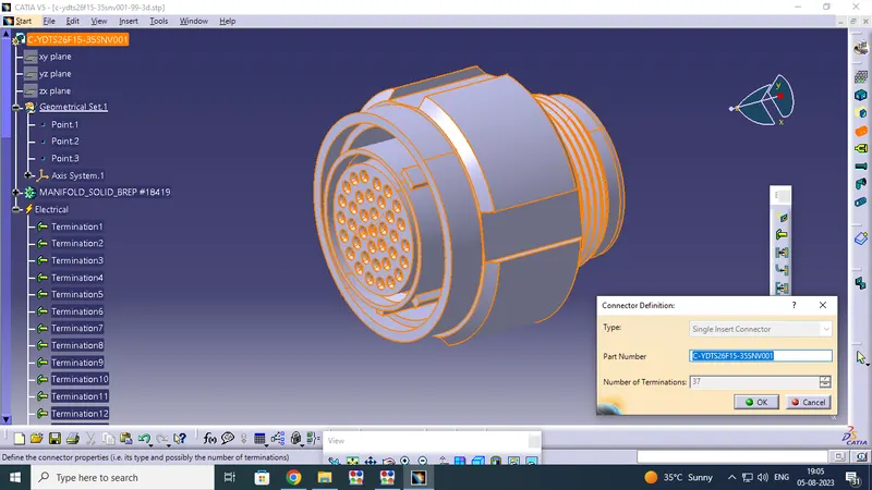
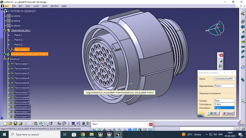
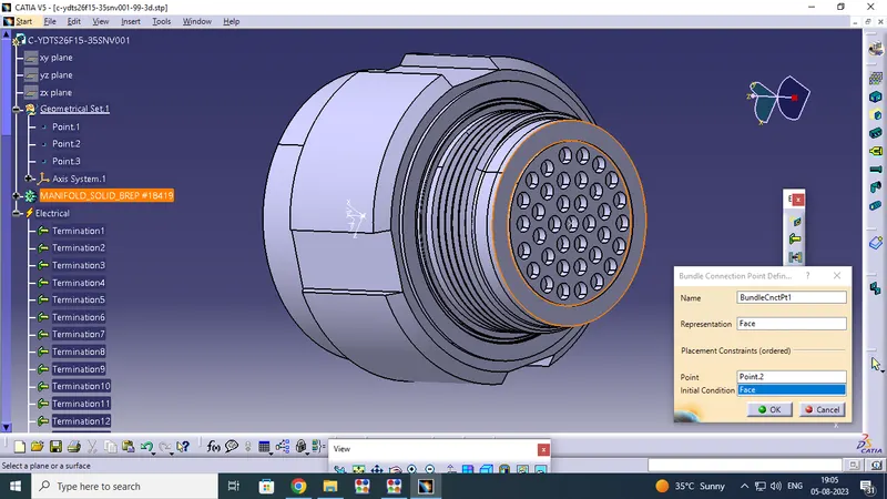
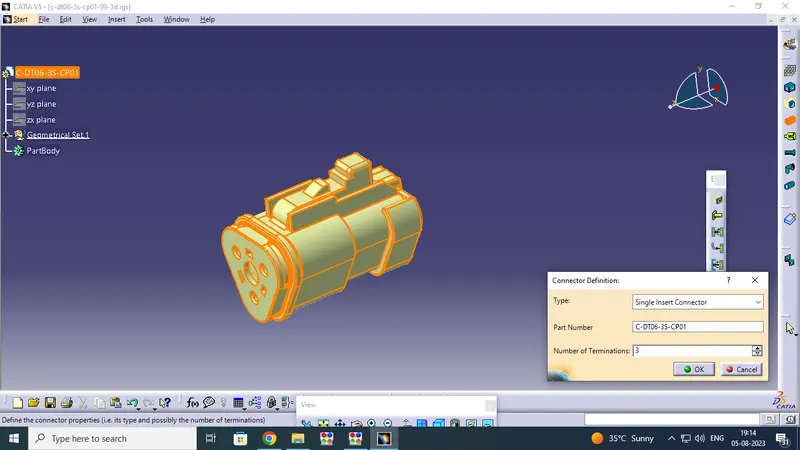
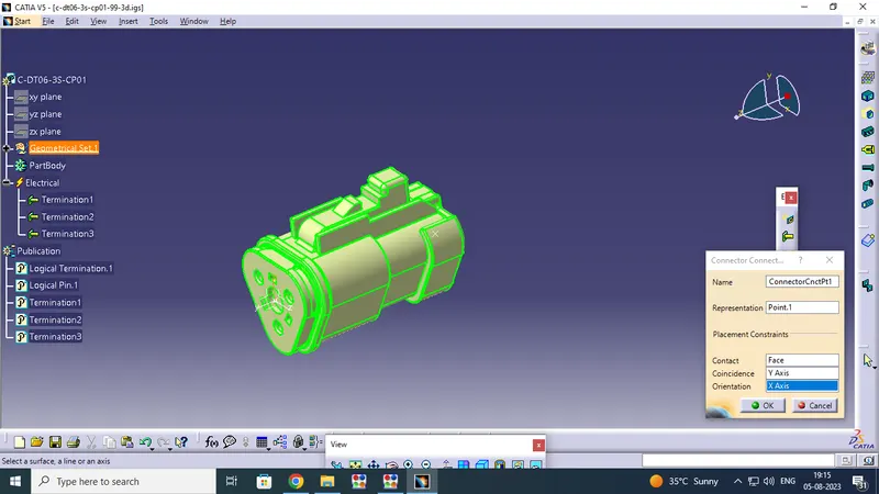
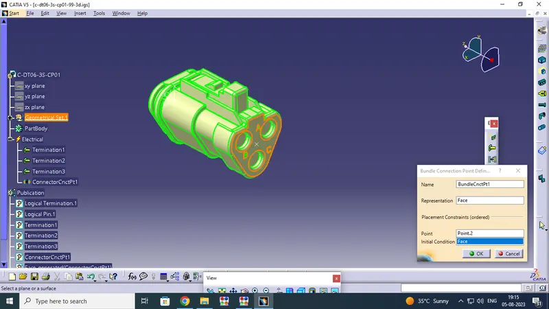
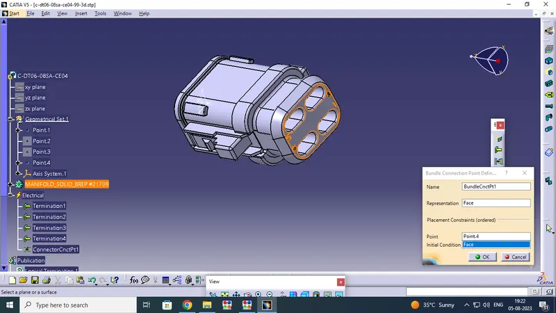
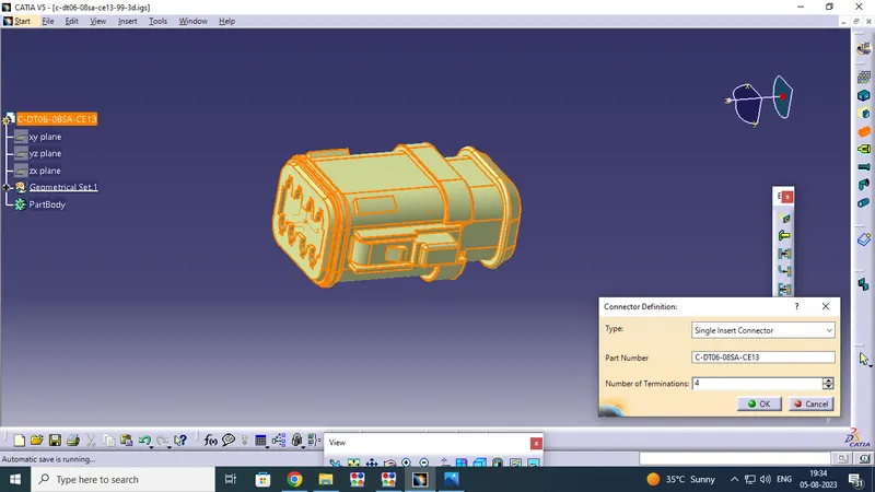
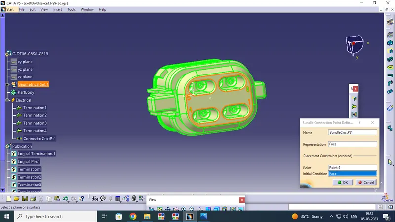
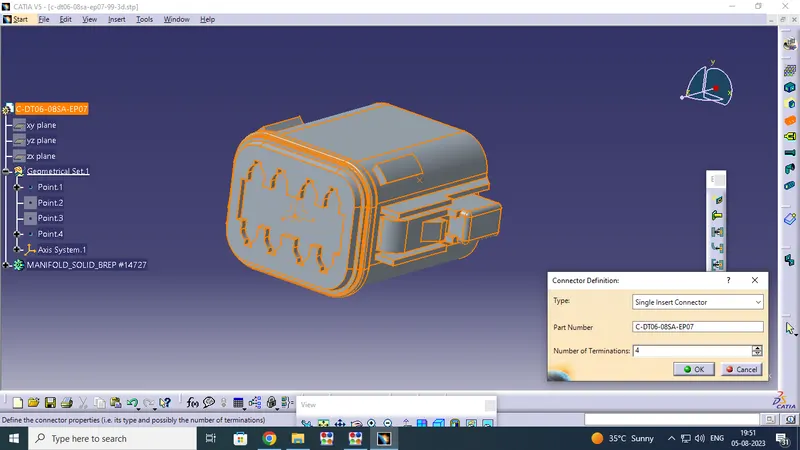
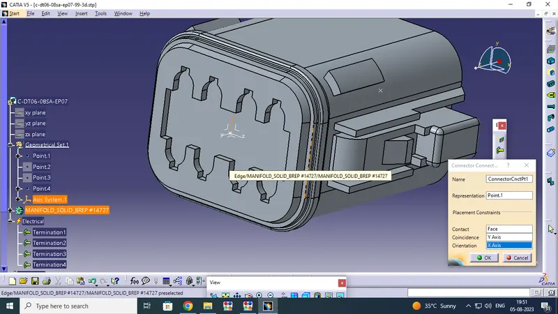
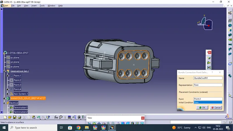
After this process we have been pick on define connector option .The define connector window is open Enter the type - single insert connector , Number of terminitions and click ok. next pick on connector connectivity point and give require detailes like , representing point - Point , Contact - Face , y - direction - coinsidence , X - direction is oriendation and click ok , at same time we have been open on Bundle connection point give the representation side - face , point , Initial condition - face and say ok.
IMAGES FOR MECHANICAL CONNECTORS TO ELECTRICALY:

CATAOLOGUE DOCUMENT CREATION:
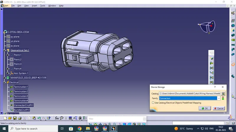
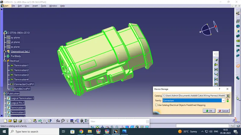
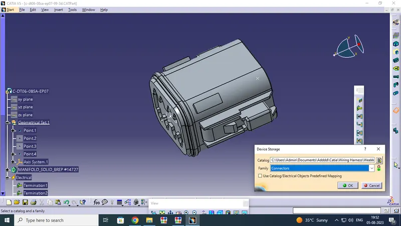
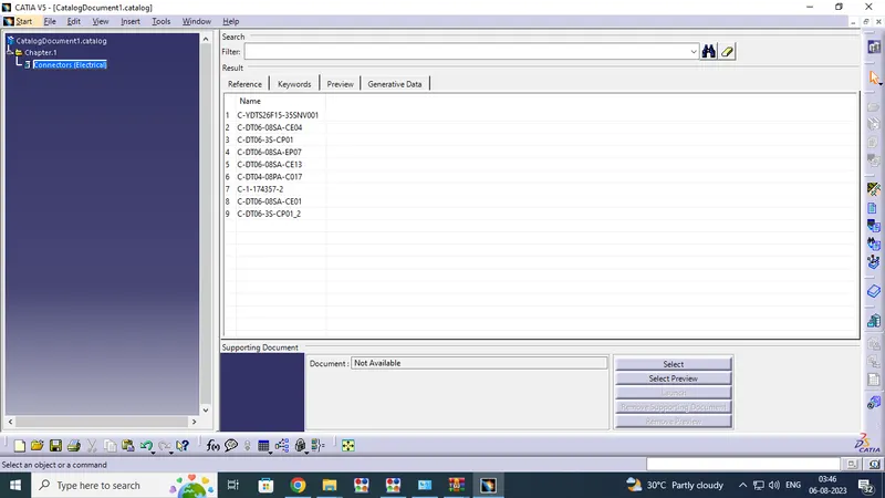
Then part will be add on storage device .if you add family first we want catalogue document.so create the catalogue document by using File - new - click catalogue document option open the window click on Add family option open on small window . thwe window ask for name - CONNECTOR and select which type we want to save ex : ELECTRICAL , then say ok. next pick add part familly option open window default name and type -ELECTRICALthen say ok .
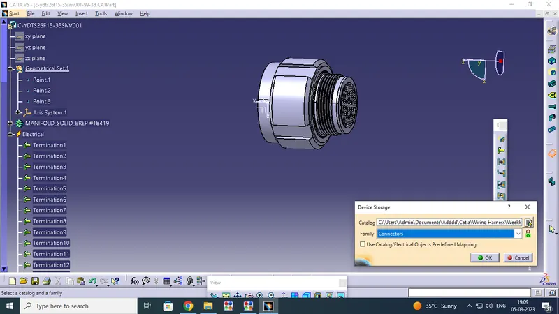
finally open the electrical part design work bench select device storage tool click on add familly go to folder location ,pick on catalogue document file and say ok.next come to storage device window select family CONNECTORS and say ok the PRODUCT will have been saved on catalogue document.
CREATION FOR HARNESS_B :
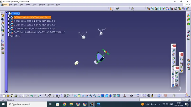
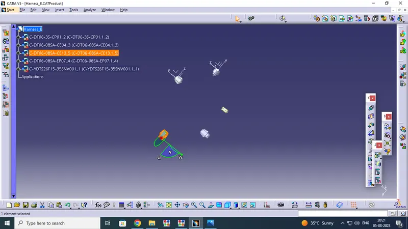
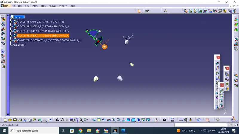
Next we have decide the Assemble HARNESS_B and routing the cable for the all connectors .So open the Product file and change the assembly design work bench ,give the name of HARNESS_B . So start the Assemble process go to pick on new component option go to the location select and open on all required connectors , Like
1.c-ydts26f15-35snv001-99-3d
2.c-dt06-3s-cp01-99-3d
3.c-dt06-08sa-ce04-99-3d
4.c-dt06-08sa-ep07-99-3d
5.c-dt06-08sa-ce13-99-3d.
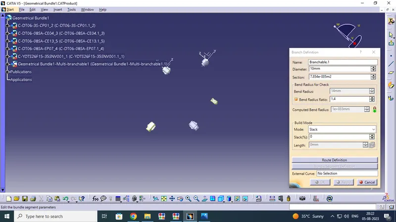
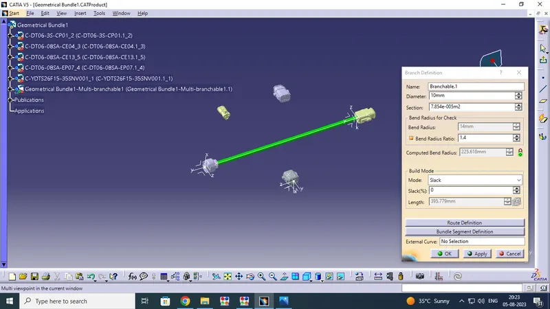
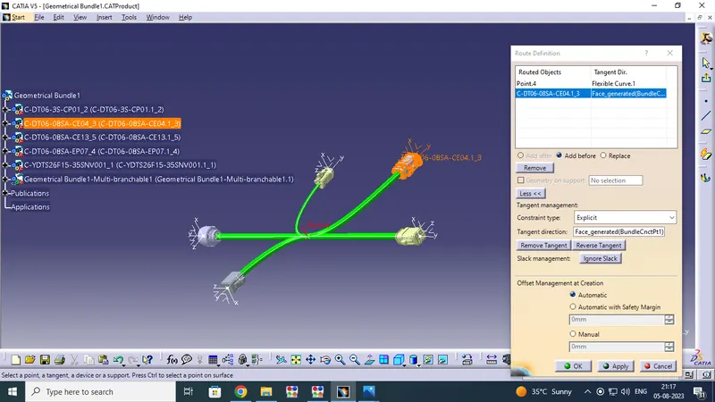
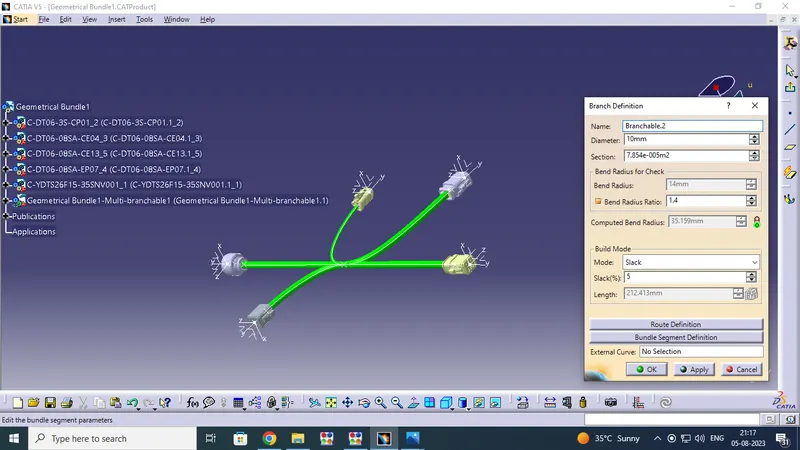
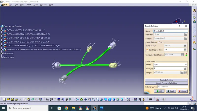
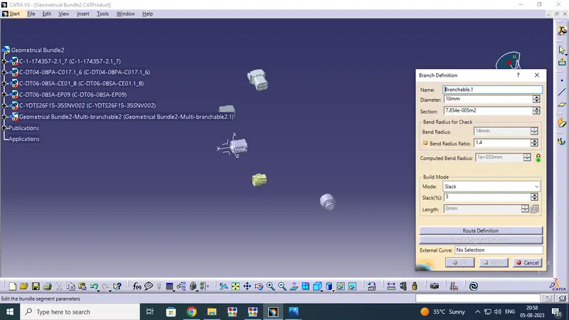
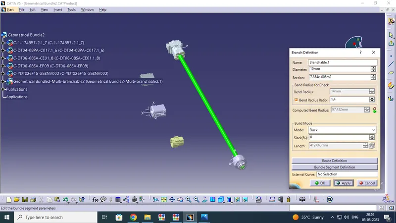
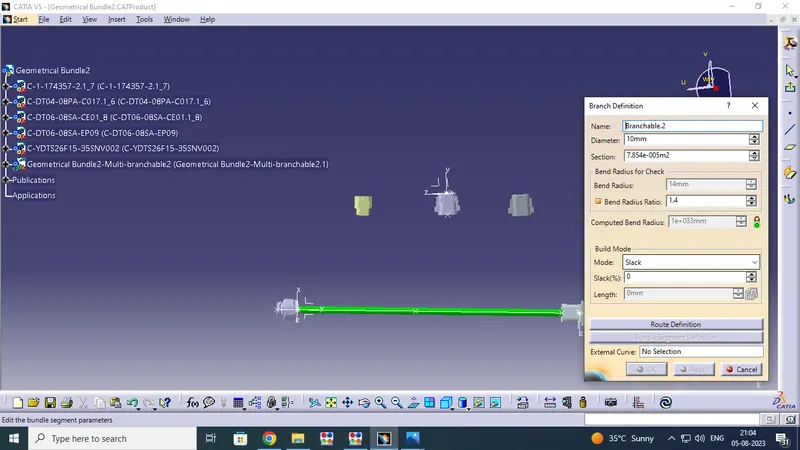
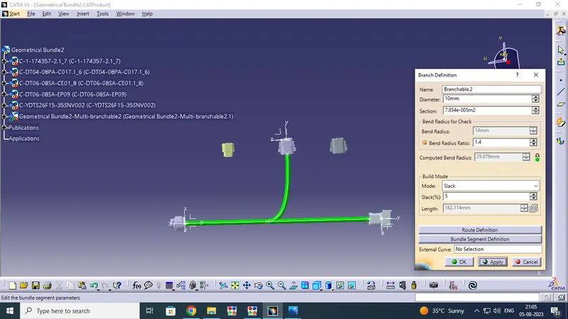
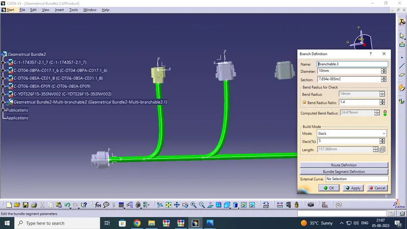
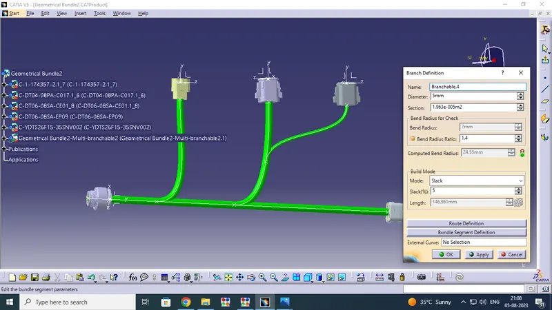
Then Assemble for the all connectors by using assemble option like , ( manupulation,rotation, snap & compass - commands )and assemble area ,length and dimension are fix in as per layout.when will complete the assemble process then start for routing process.First change the electrical Harness assembley workbench and ensure thet you have your harness geometrical bundle id highlighted.select icon on electrical Harness assembley and pick on product .next we have select the Muiti branch document icon open the branch definition window box input all required values like :name : Branchable .1 , Daimeter : 10 mm (this is main trunk branch routing diameter )and We have added additional 3 sub branches are routing in this challange . the Sub branch routing Diameter are 10mm Dia & 5mm Dia. Section: 1:13Ie-004m2 (its automatically created),Bend radius : 14mm,Bend radius ratio : 1.4 and mode : slack :5 & 8 (Which are we want only)
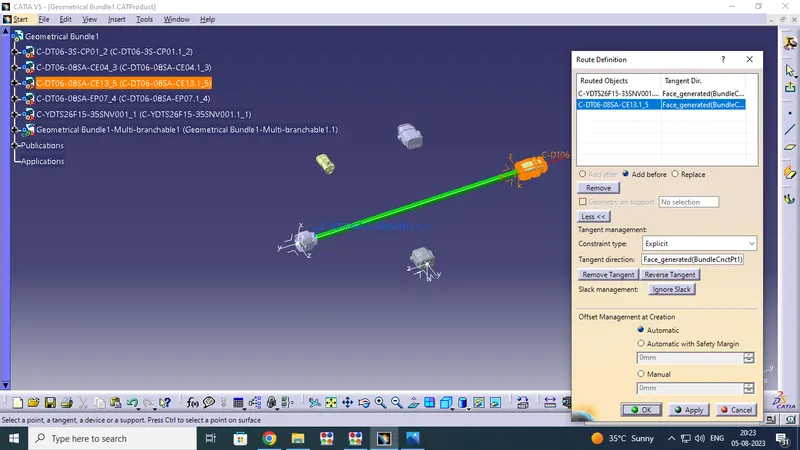
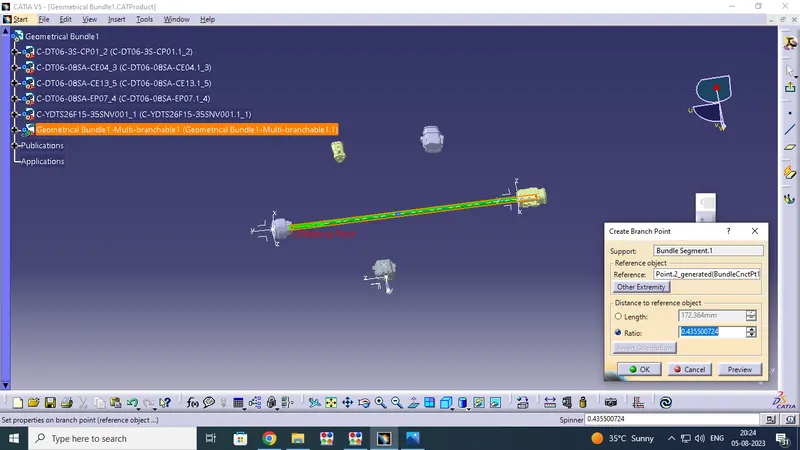
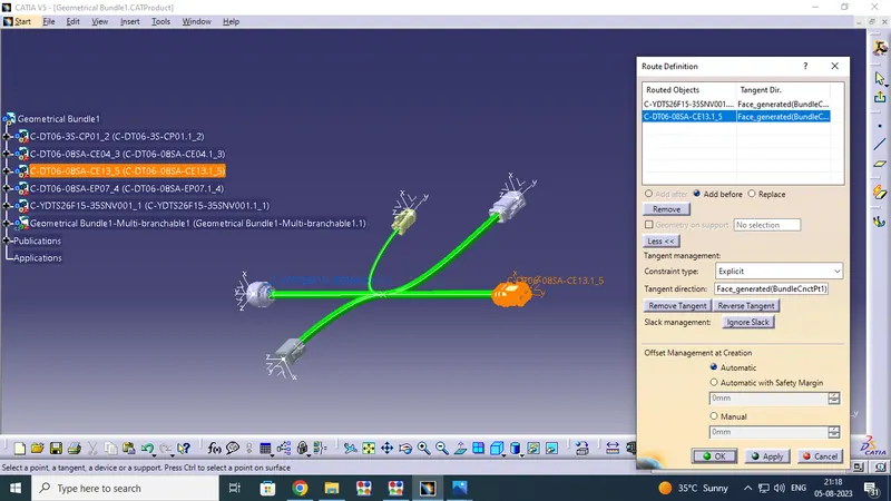
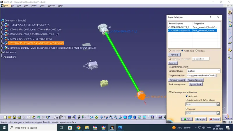
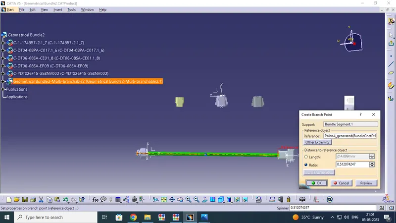
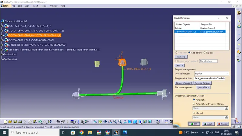
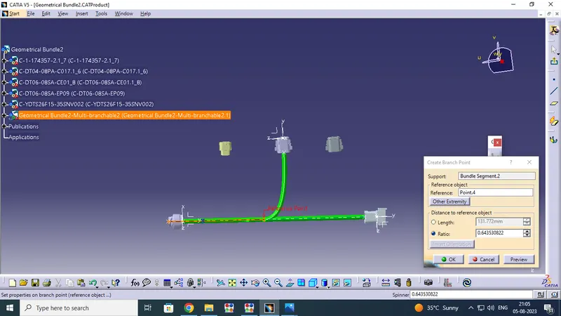
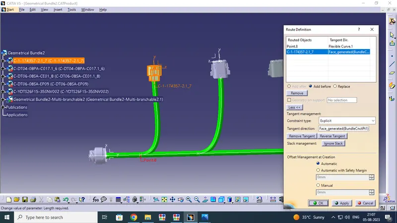
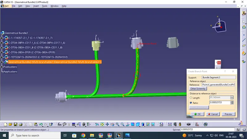
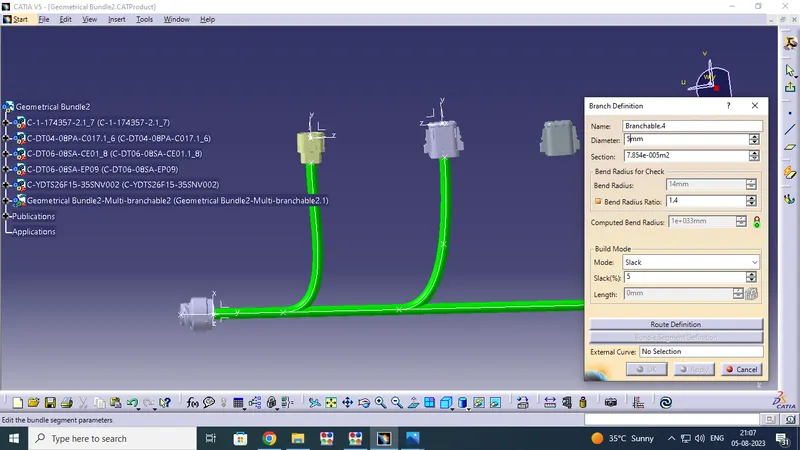
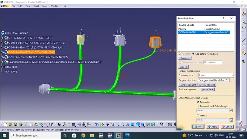
After the input valves click on Routing Definition Option Select one end connector Bundle connectivity point side and change or ensure bundle direction by using reverse tangent option and ensure the Add After option are highlighted , select the next connector bundle connection side is connected after complete this process the cable have routed successfully. after full main trunk routing is complete add branch point option .select this option open on the window select refernce point give length ( Assuming ) value from referance point and say ok the brance point will be created. after create branch point click Branch definition option give the routing diameter like: 10mm & 5mm click routing definition option on branch definition window select branch area ensure the branch direction by using reverse tangent option and go to add after option are highlighted then pick on next connector bundle connection point side finally the branch rougthing will be craeted .
IMAGES FOR ASSEMBLE AND ROUTING FOR HARNESS B
 \
\
CREATION FOR HARNESS_A :
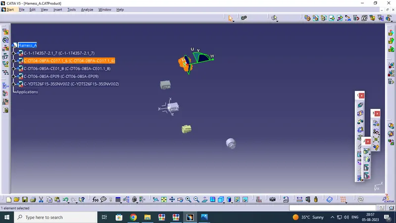
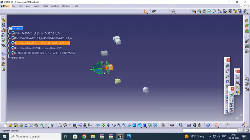
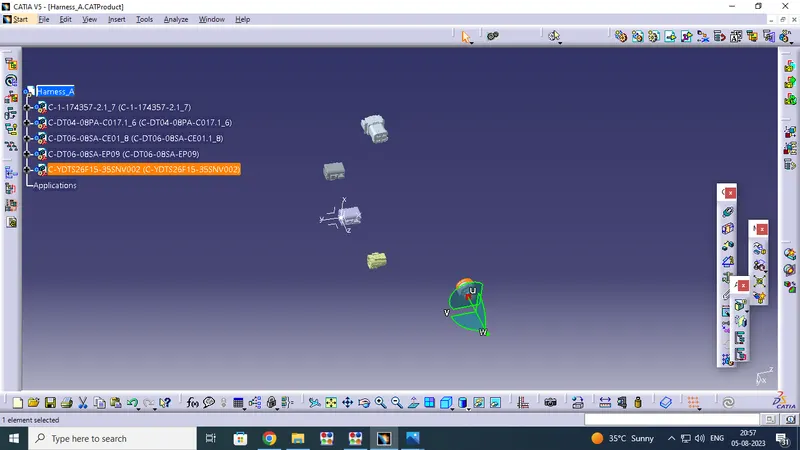
Next Same process doing HARNESS_A Creation and routing the cable for the all connectors .So open the Product file and change the assembly design work bench ,give the name of HARNESS_B . So start the Assemble process go to pick on new component option go to the location select and open on all required connectors , Like
6.c-dt04-08pa-c017-99-3d
7.c-1-174357-2-e-3d
8.c-dt06-08sa-ce01-99-3d
9.c-dt06-08sa-ep07-99-3d
10.c-ydts26f15-35snv001-99-3d
Assemble for the all Selected connectors by using assemble option like , ( manupulation,rotation, snap & compass - commands )and assemble area ,length and dimension are fix in as per layout.when will complete the assemble process then start for routing process.First change the electrical Harness assembley workbench and ensure thet you have your harness geometrical bundle id highlighted.select icon on electrical Harness assembley and pick on product .next we have select the Muiti branch document icon open the branch definition window box input all required values like :name : Branchable .1 , Daimeter : 10 mm (this is main trunk branch routing diameter )and We have added additional 3 sub branches are routing in this challange . the Sub branch routing Diameter are 10mm Dia & 5mm Dia. Section: 1:13Ie-004m2 (its automatically created),Bend radius : 14mm,Bend radius ratio : 1.4 and mode : slack :5 & 8 (Which are we want only)
After the input valves click on Routing Definition Option Select one end connector Bundle connectivity point side and change or ensure bundle direction by using reverse tangent option and ensure the Add After option are highlighted , select the next connector bundle connection side is connected after complete this process the cable have routed successfully. after full main trunk routing is complete add branch point option .select this option open on the window select refernce point give length ( Assuming ) value from referance point and say ok the brance point will be created. after create branch point click Branch definition option give the routing diameter like: 10mm & 5mm click routing definition option on branch definition window select branch area ensure the branch direction by using reverse tangent option and go to add after option are highlighted then pick on next connector bundle connection point side finally the branch rougthing will be craeted .
FINAL ASSEMBLY FOR HARNESS B & HARNESS A :
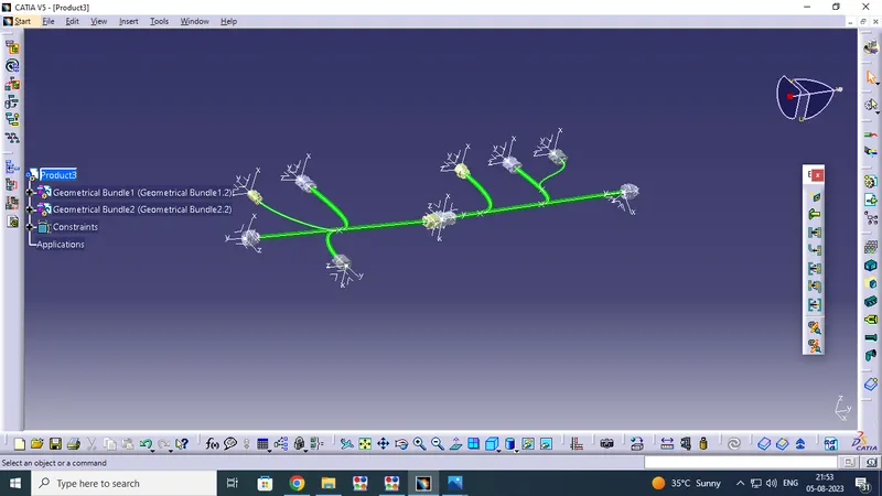
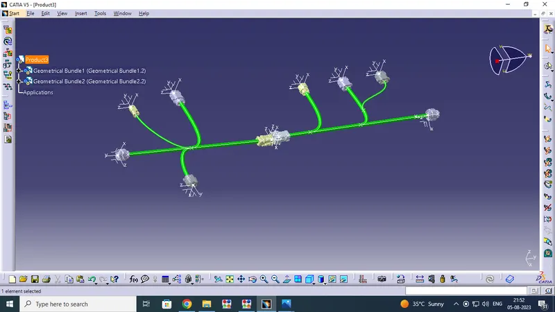
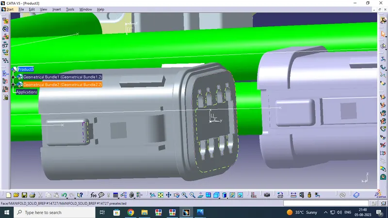
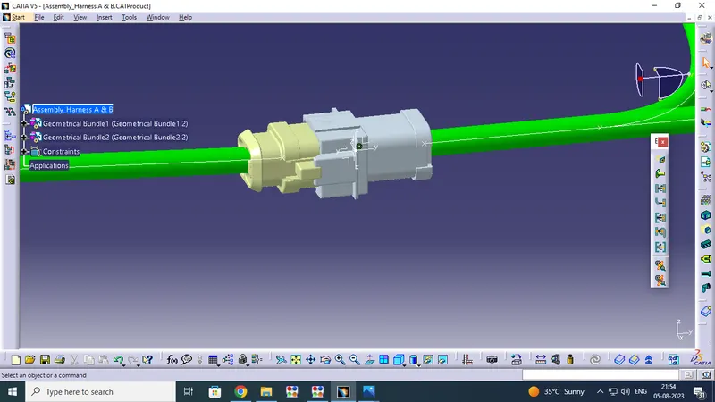
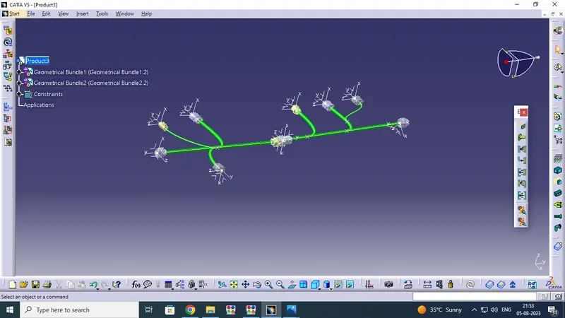
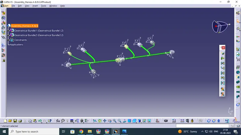
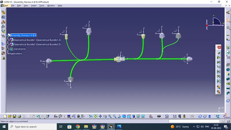
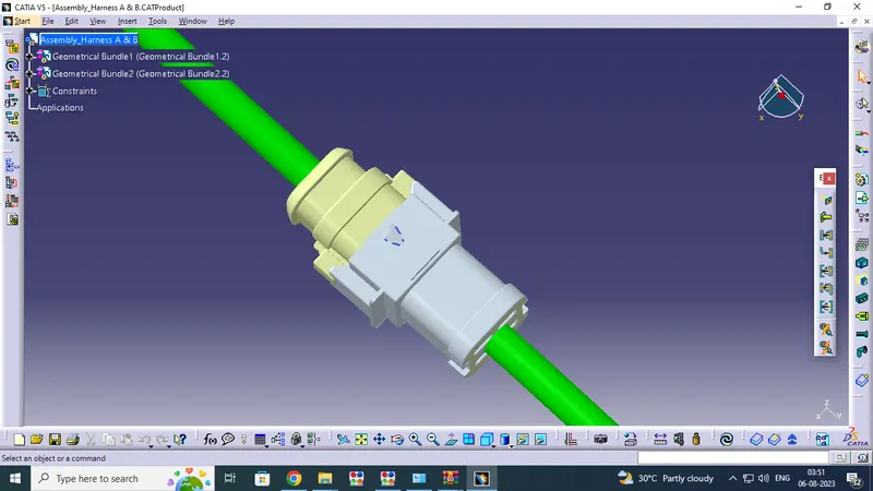
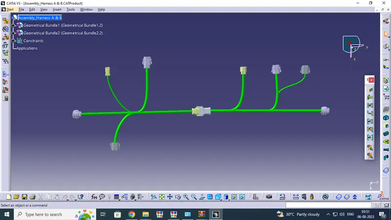
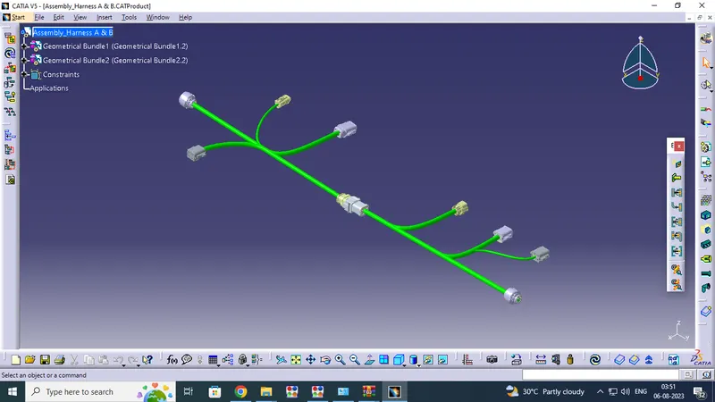
Open the New product (Name : Assembly _Harness A & B) window by using CATIYA V5 and Copy to Assembly Harness_B and Harness_A to past the new Assemble Product window .then change the Assemble part workbench and assemble to the both harness assembles as per layout diagram .After complete the process change in workbench window is assembly workbench to Electrical Assembly Design Workbench ( Start - Equipment& Systems - Electrical Harness Discipline - Electrical Assembly Design work bench)
Open the Electrical Harness Assembly work bench Select Ctrl + U Command and pick on connect electrical Device option and select to Harness Connector Axis point which side you want to connect .Finally the harness have connected.
Check for the bundle warning:
I have faced Bundle waring for Product Assembly workbench in Assemble to Harness B & Harness A.After Prepare the Harness B & Harness A then Copy and Past in Product Assembly Workbench for both Harness Assembles the warning Box are showing the window .They are Same Product Name is Not allowed in this workbench only the UNIQUE name product only allowed.Because we have use two same model connectors are used in Harness Assembly.Thats why the warning has to showing the window.
If you ignore the warning create UNIQUE name of the connectors and add on assembly workbench.